Kenmore 640-106145-113 Owner's manual
- Category
- Barbecues & grills
- Type
- Owner's manual
This manual is also suitable for

/_ CAUTION:
Read and follow all safety statements, assembly
instructions, and use and care directions before
attempting to assemble and cook.
INSTALLER/ASSEMBLER:
Leave this manual with consumer.
CONSUMER:
Keep this manual for future reference.
/_ WARNING:
Failure to follow all manufacturer's instructions
could result in serious personal injury and/or
property damage.
CAUTION:
Some parts may contain sharp edges -
especially as noted in the manual! Wear
protective gloves if necessary.
Printed n China• 463720607• 463720807. 80009263 • 1121 06

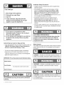
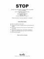
if you smell gas:
1. Shut off gas to the appliance.
2. Extinguish any open flame.
3. Open lid,
4. if odor continues, keep away from the
appliance and immediately call your gas
supplier or your fire department.
Installation Safety Precautions
Use grill only with LP (propane) gas and the regulator/valve
assembly supplied.
Grill installation must conformwith localcodes, orin their
absence with National Fuel Gas Code, NFPA 54 / ANSI
Z223,1 and Natural Gas and Propane Installation Code,
CSA B149,1. Handling and storage of LP cylinders must
conform to LPGas Code NFPA/ANSI 58, Grill is notfor use in
or on recreational vehicles and/or boats.
. All electrical accessories (such as rotisserie) must be
electrically grounded in accordance with local codes, or
National Electrical Code, ANSI / NFPA 70. Keep any
electrical cords and/or fuel supply hoses away from any hot
surfaces.
. This grill is safety certifiedfor use in the United Statesonly. Do
not modifyfor use in any other location. Modification will result
in a safety hazard.
1. Do not store or use gasoline or other
flammable liquids or vapors in the vicinity of
this or any other appliance.
2, An LP cylinder not connected for use shall not
be stored in the vicinity of this or any other
appliance,
Call Grill Service Center for Help and Parts
. Ifyou need assistance with your product or warranty parts call
%800-241-7548, Hours of Service Center Operation are
8:00 A.M. To 6:00 P.M. EST Monday- Friday.
. Toorder non-warranty replacement parts or accessories
pleasevisit uson theweb at www.charbroil,corn or call
1-800-241-7548 and one of our friendly and knowledgeable
agents will be glad to assist you.
IMPORTANT: Fill out the product record information below.
CALIFORNIA PROPOSITION65
Combustion by-products producedwhen using this
productcontain chemicals known to the State of
California to cause cancer, birth defects, and other
reproductive harm.
Safety Symbols
The symbols and boxes shown below explain what each heading
means. Read and follow all of the messages found throughout
the manual.
DANGER: Indicatesan imminentlyhazardous situation
which, if not avoided,will resultin death or serious injury.
WARNING: Indicatesan potentially hazardoussituation
which, if not avoided, could result in death orserious
injury.
Model Number
Serial Number
Date Purchased
See rating label on grill for serial number.
CAUTION
For residential use only. Do not use for commercial
cooking.
CAUTION: Indicates a potentially hazardous situation or
unsafe practice which, if not avoided, may result in minor
or moderate injury.
2 . 463720607. 463720807

ForYour Safety...................................... 2
Grill Service Center................................... 2
Product Record information............................ 2
installationSafety Precautions .......................... 2
Safety Symbols...................................... 2
Use and Care .................................... 4-10
Parts List .......................................... 11
Parts Diagram...................................... 12
Assembly ....................................... 13-23
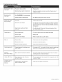
Troubleshooting.................................. 24-25
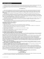
Limited Warranty.................................... 26
Registration Card ................................... 27
Do not attempt to repair or alter the
hose/valve/regulatorfor any "assumed" defect. Any
modification to this assembly will void your warranty
and create the risk of a gas leak and fire. Use only
authorized replacement partssupplied by
manufacturer.
CertifiedGrillPartsAnd Accessories@,Char-BroilandDesign@,Char-Broil(GasGriltBriquettes)@,Char-Diamonds@,CookingZoneand Design@,DiamondFlame®,ExecutiveChefQ,Faststart®,Flare
Fighter@,FlavorMaster_,GasGritlSilouetteandDesign@,H20 Smoker@,LavaFlame®,MasterFlame@,MasterFlamePrecision CookingSystem@,PowerSpark@,Quantum@,VIP@,PrecisionFlameand
Design@,SierraS, andTreFlame@are registeredTrademarksoftheW.C. BradleyCompany, Thermos@is a registeredtrademarkofthe ThermosCompany anditsaffiliates,
Artisan Collectionby Char-BroilT,_C3 and DesignTM, Cbar-BroitandDesignTM, FtameDesignTa,FlavorTects'rMGrill 2GoTM, Grillin'StickTM, Keeperofthe FlameTM, Keepersof the FlameTM, NaturatGripTM,
OutdoorCookingCollectionand DecignTM, PatioBistroTM, PrecisionFlameTM, Pro-CheckTM, QuickSetGrills andDesignTM, SmokerTentsTM, The Big EasyTM, The MinuteGrilM'_,The EdgeTM, The Tuscan
CollectionTM, andThe UrbanGrittTM are Trademarksofthe W,C,BradleyCompany, UniversalGrillPartsand DesignTM isa trademarkoftheThermos Companyanditsaffiliatec.
Protectedunderone or moreofthe followingU,S. Patents: 4,598,692;4,624,240;4,747,391; 4,747,391;4,817,583;4,924,846;4,989,579;5,003,960;5,078,256;5,078,257;5,090,398;5,109,834;5,224,676;
5,277,106;5,421,319;5,44t ,228;5,452,787;5,458,309;5,586,608;5,588,608;5,579,755;5,582,094;5,613,486;5,649,475;5,708,797;5,711,883;0,765,543;5,931,149;5,996,573;6,095,t32; &135,104;
6,173,844B1;6,279,566;6,397,731;6,410,923;6,439,222;6,523,461;8,935,327;D202,819;D339,714;D341,292;D343,337;D358,059;D381,468;D364,535;D372,637; D373,701;D377,735;D383,035;
D397,gt0; D405,643;D405,643;D406,085;D406,009;D413,043;D413,229;D413,229;D414,982; D415,380;D418,164;D416,441;D416,441;D417,587;D422,518;D423,274;D423,078;D42&303; D435,398;
D438,004;D438,059;D438,080;D438,427;D439,110;0442,505; D443,179;D443,354;D447,304;D447,385;D447,909;D440,610;D448,814;D440,615;D44&816; D448,975;D449,492; 0451,759;D456,202S;
D480,313,D461,359andD504,048.Canada: 87743;07744;92807;92808 and1,318,424.OtherPatentsPending,Assemblyinstructions@2008.
463720607• 463720807,3

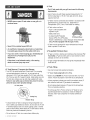
LP Tank
T
• NEVER store a spare LP tank underorneargrillorin
enclosed areas
Never fill the cylinder beyond 80% full.
• An overfllled or improperly stored tank is a hazard due
to possible gas release from the safety relief valve.
• if you see, smell or hear escaping gas, immediately get
away from the LP tank/grill and call your fire
department.
If the above is not followed exactly, afire causing
death or serious injury may occur.
• The LP tank used with your grill must meet the following
requirements:
• Use LP tanks only with these required measurements: 12"
(30.5cm) (diameter) x 18" (45.7 cm) (tall) with 20 lb. (9 kg.)
capacity maximum.
, LP tanks must be constructed and marked in accordance with
specifications for LP tank of the U.S. Department of
Transportation (DOT). See LP tank collar for marking.
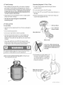
• LP tank valve must have:
, Type I outlet compatible with
regulator or grill.
, Safety reliefvalve.
, ULlisted Overfill Protection
OPDHandWheel
Device (OPD). This OPDsafety
feature is identified by a unique triangular hand wheel. Use
only LP tanks equipped with this type of valve.
, LP tank must be arranged for vapor withdrawal and include
collar to protect LP tank valve.
LP (Liquefied Petroleum Gas)
• LP gas is nontoxic, odorless and colorless when produced. For
Your Safety, LP gas has been given an odor (similar to rotten
cabbage) so that it can be smelled.
• LP gas is highlyflammable and may ignite unexpectedly when
mixed with air.
LP Tank Removal, Transport And Storage
, Turn OFF all control knobs and LP tank valve. Turn coupling
nut counterclockwise by hand only - do not use tools to
disconnect. Lift LP tank wire upward off of LPtank collar, then
lift LP tank up and off of support bracket. Installsafety cap onto
LP tank valve.Always use cap and strap supplied with valve.
Failure to use safety cap as directed may result in serious
personal injury and/or property damage.
LP TankValve
Safety Cap
Retainer Strap
, A disconnected LP tank in storage or being transported must
have a safety cap installed (as shown). Do not store an LP tank
in enclosed spaces such as a carport, garage, porch, covered
patio or other building. Never leavean LP tank inside a vehicle
which may become overheated bythe sun.
, Do not store an LP tank in an area where children play.
4 . 463720607,463720807
LP Tank Filling
Use only licensed and experienced dealers.
• LP dealer must purge tank beforefilling.
• Dealer should NEVERfill LP tank more than 80% of LP tank
volume. Volume of propane in tank will vary by temperature.
• A frosty regulator indicates gas overfill, immediately close LP
tank valve and call local LP gas dealer for assistance.
, Do not release liquid propane (LP) gas into the atmosphere.
This is a hazardous practice.
, Toremove gas from LP tank, contact an LP dealer or call a
local fire department for assistance. Check the telephone
directory under "Gas Companies" for nearest certified LP
dealers.

LP Tank Exchange
, Many retailers that sell grills offer you the option of replacing
your empty LPtank through an exchange service. Use only
those reputable exchange companies that inspect, precision fill,
test and certify their cylinders. Exchange your tank only for
an OPD safety feature-equipped tank as described in the
"LP Tank" section of this manual,
Always keep new and exchanged LP tanks in upright position
during use, transit or storage.
, Leak test new and exchanged LP tanks BEFORE
connecting to grill.
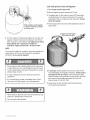
Connecting Regulator To The LP Tank
1. LP tank must be properly secured onto grill. (Refer to
assembly section.)
2. Turnall control knobs to the OFF position.
3. Turn LP tank OFF by turning OPD hand wheel clockwise to a
full stop.
4. Remove the protective cap from LP tank valve.Always use
cap and strap supplied with valve.
LP Tank Leak Test
For your safety
Leak test must be repeated each time LP tank is exchanged or
refilled.
Do not smoke during leak test.
Do not use an open flame to check for gas leaks.
Grill must be leak tested outdoors in a well-ventilated area,
away from ignition sources such as gas fired or electrical
appliances. Duringleak test, keep grill away from open flames
or sparks.
, Usea clean paintbrush and a 50/50 mild soap and water
solution. Brush soapy solution onto areas indicated by arrows
in figure below. Leaks are indicated bygrowing bubbles.
If "growing" bubbles appeardo not use or move the LP tank.
Contact an LP gas supplier or your fire department!
A Do not use household cleaning agents. Damageto gas
train components can result.
Do not use a POL transport plug
(plastic part with external threads)!
Itwill defeat the safety feature of
the valve.
5. Hold regulator and insert nipple into LP
tank valve. Hand-tightenthe coupling
nut, holding regulator in a straight line
with LP tank valve soas not to cross-
thread the connection.
Nipplehasto becentered
intothe LPtank valve.
463720607 * 463720807.5

Holdcoupling nut and regulator
asshownfor proper connection
to LP tank valve.
Leak Testing Valves, Hose and Regulator
1. Turn all grill control knobs to OFF.
2. Be sure regulator istightly connected to LP tank.
3. Completely open LP tank valve byturning OPD hand wheel
counterclockwise, if you hear a rushing sound, turn gas off
immediately.There is a major leak at the connection. Correct
before proceeding.
4. Brush soapy solution onto areas where bubbles are shown in
picture below:
6. Turnthe coupling nut clockwise and tighten to a full stop.The
regulatorwill seal on the back-checkfeature in the LP tank
valve, resulting in some resistance.An additional one-half to
three-quarters turn is required to complete the
connection, Tighten by hand only - do not use tools,
NOTE:
if you cannot complete the connection, disconnect regulator and
repeat steps 5 and 6. if you are still unable to complete the
connection, do not use this regulator!
, Donot insert any tool or foreign objects into the valve outlet
or safety reliefvalve. Youmay damage the valve and cause
a leak. Leaking propane may result in explosion, fire, severe
personal injury,or death..
, if a leak is detectedat any time, STOPand call the fire
department.
, if you cannot stop a gas leak, immediately close LP tank
valve and call LP gas supplier or yourfire department!
A Never remove threaded
orifice at end of valve.
,
,
If "growing" bubbles appear,there is a leak. Close LP tank
valve immediately and re-tighten connections. If leaks cannot
be stopped do not try to repair, Callfor replacement parts.
Order new parts by giving the serial, model number, name and
part numberof items needed (see parts list) to the Grill
Service Center at 1-800-241-7548.
Always close LPtank valve after performing leak test by
turning hand wheel clockwise.
, Never attempt to attach this grill to the self-contained LP gas
system of a camper trailer or motor home.
, Donot usegrill until leak-tested.
6 . 463720607,463720807

For Safe Use Of Your Grill And To Avoid Serious
injury:
* Donot letchildren operate or play near grill.
Keep grill area clear and free from materials that burn.
Donot block holes in bottom or back of grill.
Check burnerflames regularly.
Use grill only in well-ventilated space. NEVER use in
enclosed space such as carport, garage, porch, covered
patio, or under an overhead structure of any kind.
Donot usecharcoal or ceramic briquets in a gas grill.
(Unlessbriquets are supplied with your grill.)
* Use grill at least 3 ft. from any wall or surface. Maintain
10ft. clearance to objects that can catch fire or sources of
ignitionsuch as pilot lights on water heaters, live electrical
appliances, etc.
Apartment Dwellers:
Checkwith management to learn the requirements and fire
codes for using an LP gas grill in your apartment complex. If
allowed, use outside on the ground floor with a three (3) foot
clearance from walls or rails. Donot use on or under
balconies.
* NEVER attempt to light burner with lid closed. A buildup
of non-ignited gas inside a closed grill ishazardous.
Never operate grill with LP tank out of correct position
specified in assembly instructions.
Always close LP tank valve and remove coupling nut
before moving LP tank from specified operation
position.
Safety Tips
A Before opening LP tank valve, check the coupling nut for
tightness.
A When grill is not in use, turn off all control knobs and LP tank
valve.
A Nevermove grill while in operation or still hot.
A Uselong-handled barbecue utensils and oven mitts to avoid
burnsand splatters.
A Maximumload for shelves is 10 Ibs.
A Do not usea cooking pot larger than 9" on grid.
A The grease cup must beattached to grease cup clip and
emptied after each use. Do not remove grease cup until grill
hascompletely cooled.
A Ifyou notice greaseor other hot material dripping from grill
onto valve, hose or regulator, turn off gas supply at once.
Determine thecause, correct it, then clean and inspect valve,
hoseand regulator before continuing. Perform a leaktest.
A The regulator may make a humming or whistling noiseduring
operation. This will not affect safety or use of grill.
A Ifyou have a grill problem see the "TroubleshootingSection".
ff the regulator frosts, turn off grill and LP tank valve
immediately. This indicates a problem with the tank and it
should not be used on any product. Return to supplier!
463720607 * 463720807.7

ignitor Lighting
A Do not lean over grill while lighting.
1. Open lid during lighting.
2. Toignite, turn left knob to_ _ HIGH.
3. Push IGNITOR button rapidly.
4. If ignition does NOT occur in 5 seconds, turn the burner
controls off,wait 5 minutes, and repeat the lighting procedure.
5. Ignite right burner,turn knob to _.
6. If ignitor does not work, wait 5 minutes, then follow match
lighting instructions.
CAUTION
If burner does not light, turn knobs to OFF,wait 5
minutes, and try again. Always close valve during the 5
minute waiting period. If the burner does not ignite with
the valve open, gas will continue to flow out of the burner
and could accidentally ignitewith risk of injury.
Match-Lighting
A Do not lean over grill while lighting.
1. Open lid during lighting.
2. Place match into match holder (hanging from side of cart).
3. Push in and turn left knob to _ _ HIGHposition. Besure
burner lights and stays lit.
4. Light right burner by pushing knob in and turning to _ HIGH
position.
* Putting out grease fires by closing the lid is not
possible. Grills are well ventilated for safety reasons.
* Do not use water on a grease fire. Personal injury may
result, if a grease fire develops, turn knobs and LP tank
off.
* Do not leave grill unattended while preheating or
burning off food residue on high. if grill has not been
regularly cleaned, a grease fire can occur that may
damage the product. Follow instructions on General
Grill Cleaning and Cleaning The Burner Assembly to
prevent grease fires.
Before Your First Cookout
. Light burners, check to make sure they are lit, close the lid and
warm up grill on HIGH for 15 minutes. This curing of paint and
parts will produce an odor only on first lighting.
Burner Flame Check
. Light burner, rotate knobs from HIGHto LOW. Youshould see
a smaller flame in LOW position than seen on HIGH.Always
check flame prior to each use. If only lowflame is seen referto
"Sudden drop or low flame" in the TroubleshootingSection.
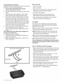
Hose Check
* Beforeeach use, check to see if hoses are cut, worn or kinked.
Replace damaged hoses before using grill. Useonly
valve/hose/regulator specified in the Parts List.
Normal Kinked
Hose Hose
8 . 463720607,463720807

Turning Grill Off
. Turn all knobs to OFF position. Turn LP tank off byturning
OPD handwheel clockwise to a full stop.
Ignitor Check
• Turn gas off at LP tank. Press and hold ignitor button. "Click"
should be heard and spark seen each time between collector
box or burner and electrodes. See "Troubleshooting"if no click
or spark.
Valve Check
Important: Make sure gas is off at LP tank before checking
valves. Knobslock in OFF position. Tocheck valves, first
push in knobs and release, knobs should spring back. If knobs
do not spring back, replace valve assembly before using grill.
Turn knobs to LO position then turn back to OFF position.
Valves should turn smoothly.
General Grill Cleaning
, Keep the outside of your grill looking new by cleaning itonce a
month with warm soap and water or a non-abrasive cleaner. If
you don't havea grill cover, wipe off dust and grime before
starting your grill.
, Coating the cooking grids with spray-on cooking oil will keepthe
food from sticking and make clean up easier.After cooking,
scrape the grates with a long handled, brass wire bristle brush.
. Check insidethe grill bottom for grease build up and clean
often, especially after cooking fatty meat.
, Do not mistake brown or black accumulation of grease and
smoke for paint. Apply a strong solution ofdetergent and water
or use a grill cleaner with scrub brush on insides d grill lid and
bottom. Rinse and allow to completely air dry. Do not apply a
caustic grillloven cleaner to painted surfaces.
• Plated wire grates: Wash grates with concentrated grill
cleaner or use soap and water solution. Dry thoroughly and
store indoors between cookouts.
. Plastic parts: Wash with warm soapy water and wipe dry.
,& Do not use citrisol, abrasive cleaners, degreasers or a
concentrated grill cleaneron plastic parts. Damage to and
failure of parts can result.
• Porcelain grates: Because of glass-like composition, most
residue can bewiped away with baking soda/water solution or
specially formulated cleaner. Use non-abrasive scouring
powder for stubborn stains.
I1 ! c ,o. II !
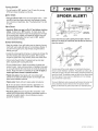
SPIDER ALERT!
CONTROL PANEl
GAS COLLECTOR
BOX &IGNITOR
/
BURNER
SPIDER WEBS
INSIDEVENTURI
VALVE AIR VENTURI
SHUTTER
If you notice that yourgrill is getting hard to light or that the
flame isn't asstrong asit should be,take the timeto checkand
clean theventuri's.
LIFTOUT
BURNER ASSEMBLY
REMOVE
BURNER
CLIPS
J
CLEAN OUT SPIDERWEBS
VENTURI INSIDEVENTURI
Insomeareasofthecountry,spidersorsmallinsectshavebeen
knowntocreate"flashback"problems.Thespidersspinwebs,build
nestsandlayeggsin thegrill'sventuritube(s)obstructingtheflowof
gastotheburner,Thebacked-upgascanigniteintheventuribehind
thecontrolpanel.Thisis knownasa flashbackanditcandamage
yourgrillandevencauseinjury.
Topreventflashbacksandensuregoodperformancetheburnerand
venturiassemblyshouldberemovedfromthegrillandcleaned
beforeusewheneverthegrillhasbeenidleforanextendedperiod.
463720607,463720807,9

Cleaning the Burner Assembly
Follow these instructions to clean and/or replace parts of burner
assembly or if you have trouble ignitinggrill.
1. Turn gas off at control knobs and LP cylinder,
2. Removecooking grate and heattent.
3. Undergrill remove grease cup, disconnect ignitorwire from
burner.
4. Insidegrill remove burner assembly (A), clean ceramic
portion of electrode with rubbing alcohol and a swab.
5. Clean outside of burner with soap and water. Lay burner
upside down on flat surface, insert garden hose to force
water through tubes. Make sure water comes out of all
burner holes. Open clogged holes with a thin wire. Shake
out excess water and examine holes. Due to normal wear
and corrosion some holes may become enlarged. Ifany
large cracks or holesare found replace burner.
6. Ifgrill is to be stored,coat burner lightly with cooking oil.
Wrap in protective cover to keep insects out.
7. Ifnot storing grill after cleaning, replace burner into grill
bottom.
VERY iMPORTANT: Burner tubes must re-engage valve
openings. See illustration (A).
8. Reattach ignitorwire to electrode.
9. Repositionheat tent and cooking grate. Reattach clean
grease cup to grease clip.
10. Before cooking again on grill, perform a "Leak Test'and
"BurnerFlame Check".
Storing Your Grill
, Clean cooking grates.
, Store in dry location.
, When LP tank is connected to grill, store outdoors in well-
ventilated space and out of reachof children.
, Cover grill ifstored outdoors.
, Store grill indoors ONLYif LP tank is turned offand
disconnected, removed from grill and stored outdoors.
, When removing grill from storage follow "Cleaning Burner
Assembly" instructions before starting grill.
Food Safety
Food safety isa very important part of enjoying the outdoor
cooking experience. Tokeepfood safe from harmful bacteria,
follow these four basic steps:
Clean: Wash hands, utensils, and surfaces with hot soapy water
before and after handling raw meat and poultry.
Separate: Separate raw meats and poultry from ready-to-eat
foods to avoid cross contamination. Usea clean platter and
utensils when removing cooked foods.
Cook: Cook meat and poultry thoroughly to kill bacteria. Use a
thermometer to ensure proper internalfood temperatures.
Chill: Refrigerate prepared foods and leftovers promptly.
For more information call: USDA Meat and Poultry Notline at
1-800-535-4555 (in Washington, DC (202) 720-3333, 10:00am-
4:00 pm EST).
Correct burner-to-valve engagement
A
Burner Tube
Valve
How To Tell if Meat is Grilled Thoroughly
* Meat and poultry cooked on a grill often browns very fast on the
outside. Usea meat thermometer to be sure food has reached
a safe internal temperature, and cut into food to check for
visual signs of doneness.
, Whole poultry should reach 180° F; breasts, 170° F.Juices
should run clear and flesh should not be pink.
, Hamburgers made of any ground meat or poultry should reach
160° F,and be brown in the middlewith no pinkjuices. Beef,
veal and lamb steaks, roasts and chops can be cooked to 145°
F.All cuts of pork should reach 160° F.
* NEVER partially grill meat or poultry and finish cooking later.
Cook food completely to destroy harmful bacteria.
* When reheatingtakeout foods or fully cooked meats like hot
dogs, grill to 165° F,or untilsteaming hot.
10 • 463720607,463720807

A 1
B 1
C 1
D 1
1
F 2
G 2
H 2
I 1
J 1
K 1
L 2
M 2
N 1
O 2
P 1
Q 1
R 1
S 1
T 1
U 1
V 1
W 1
X 2
Y 1
Z 1
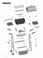
Description ................... Part#
Firebox..................... 8001006
HeatShield ................. 80010068
BurnerAssembly ............. 80010069
Lid ........................ 80010070
LogoPlate .................. 80010071
Shelves .................... 80010072
MountingBrackets, Right....... 80010073
MountingBrackets, Left........ 80010074
Support Bracket.............. 80010075
TankRetainer Bracket ......... 80010076
Leg,Upper Right ............. 80010077
Leg,Right .................. 80010078
Leg,Left.................... 80010079
Leg,Upper Left .............. 80010080
BackBraces................. 80010081
TankSupport Bracket ......... 80010082
FireboxSupport,Left .......... 80010083
FireboxSupport,Right......... 80010084
TankExclusionWire .......... 80009836
Valve/Hose/Regulator ......... 80010085
Control Panel................ 80010086
Panel...................... 80010087
Axle Rod ................... 80010088
Leg Extenders ............... 80009820
Grease Cup ................. 80000270
Grease Cup Clip ............. 80005794
AA
BB
CC
DD
EE
FF
GG
HH
II
JJ
_y
1
1
2
2
2
2
1
1
1
1
1
Description ................... Part#
TankRetainer................ 80010192
Ignitor...................... 80008322
Wheels..................... 80010191
Control Knobs ............... 80009706
Hinges,Lower ............... 80010090
Hinges,Upper ............... 80010091
Handle..................... 80010092
HeatTent................... 80009840
Cooking Grate ............... 80009841
SwingAway ................. 80009825
HardwarePack .............. 80009846
1 Wheel Bushing
2 HingePins
3 HitchPins
1 Wing Screw,#10-24x3/8"
1 Screwdriver
30 Screws, #10-24x1/2"
50 Nuts,#10-24
2 Wing Nuts, 1/4"-20
20 Screws, #10-24x1-1/4"
12 Screws, #10-24x2"
2 LockWashers
12 Fiber Washers,5mm
2 FiberWashers,7mm
463720607,463720807,11

i _iiiiii_i,i_,_iJ;_iiji_'i'¸¸i_
JJ \
z
FF
Y
FF
IH
AA
W
DD
x\
T
CC
I
V
12 • 463720607,463720807

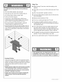
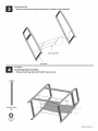
Left Leg
Place left upper leg as shown (A). NOTE: Lower left leg has two large holes at the bottom. In front, attach upper leg, tank
retainer bracket side brace and lower leg with #10-24x1-1/4" screw and #10-24 nut (B). In back, place screw #10-24x1-1/4"
screw and #10-24 nut. Do not tighten.
Attach tank support bracket in second hole from bottom of leg with a hinge pins and hitch pins.
Do not tighten
this screw and nut
untie step 4
B
Upper Left Leg
A
LowerLeft Leg
#10=24Nut
Qty:2
Correctlyassembledleftleg
#10-24x1-1/4"
Screw
Qty:2
Front
Tank Support Bracket
Notchs to hold LP cylinder
HitchPin
Qty:2
HingePin
Qty:2
463720607 * 463720807,13

Right Leg
[] Placeright upperlegas shown(A).Attachupperlegandlowerlegwith#10-24×14/4"screwsand#10o24nuts (B).
[] Attachsupport bracketwith#10o24×1=1/4"screwsand#10o24nuts=
UpperRightLeg
Front
\
Correctlyassembledrightleg
A
#10-24Nut #10-24x1-1/4"
Qty:4 Screw
Qty:4
Donot tighten
thisscrewand nat
until step4
! i
/ ,
LowerRightLeg
SupportBracket
14 • 463720607• 463720807

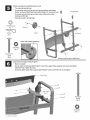
TankExclusionWire
[] Hooktankexclusionwireintolegswithopeningfor LPcylinderon tankbracketside.
TankExclusionWire
TankBracket
FrontPanel
Layfront legs down on the floor°
[] Slidepanelunderlegs.Attachwith#10o24×2"screwsandnuts.
#10-24x2"Screw
Qty:4
0
#10-24Nut
Qty:4
463720607•463720807• 15

Wheels,LegExtendersandBack Bracesto Cart
Turnassembly upsidedown.
On both sides removescrews and nuts from tank retainerand support
bracket asshown.Attach back braceswith #10-24x1-1/4"screws and nuts.
Insertaxmerod intowheel, legsand otherwheel.Attachwith a wheel
bushing and hitch pin.
Push legextenders intoright legs.
LegExtenders
WheelBushing
Qty:l
Qty:l
AxleRod
\
Wheel
"Cone" side of wheel against leg
BackBrace
#10-24 Nut
Qty: 6 /
#I0-24x1-1/4" "....
Screw \
Qty: 6 Removescrews and nuts to attach brace
Control Panel and Upper Firebox Supports
Stand cart upright,
In front, attach control panel with #10-24x2" screws, Place upper firebox supports onto screws and tighten
with #10-24 nuts, Tighten all screws.
In back leg, attach upper firebox support with #10-24x2" screws and #10-24 nuts, Do not tighten,
Control Panel
#10-24x2"
Screws
Qty:8
@
#10-24 Nut
Qty: 8
10 * 463720607,463720807

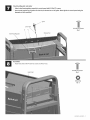
Valve/Hose/Regumatorand ignitor
Attachvalve/hose/regulatorassembly to control panelwith #10-24xl/2" screws.
insert round terminal mugof ignitorwire intothe pin mocatedon endof ignitor.Attach ignitorto contrompanel using the
stampednut that'sprovided.
Ignitor
Valve/Hose/Regulator
IgnitorWire
I:: _, #10=24x1/2"Screw
_ Qty:2
Stam
HeatShield
[ Attachheatshieldwith#10-24xl/2"screwsand#10-24nuts.
Heat Shield
#10-24x112"Screw
Qty:2
#10-24Nut
Qty:2
463720607,463720807,17

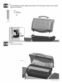
Tank Retainer
insert tank retainer into bracket and secure with wing screw.
ii! i
#10-24x3/8"WingScrew
Qty:
Tank
Retainer
A
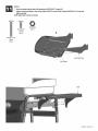
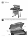
Burner, Firebox and Control Knobs
Place burner assembly into firebox (A). Fasten the burner assembly to the firebox using 5ram fiber washers and
#8 sheet metal screws. Insert #10-24x1-1/4" screws into each side of firebox, inside firebox attach 5ram fiber washers and
#10-24 nuts to screws,
Place firebox onto upper firebox supports. Make sure burner tubes are correctly engaged (B). If burner is not leveled from
left to right, adjust the two screws attaching valve to control panel. Attach short ignitor wire to ignitor (B),
Attach firebox with #10-24x1-1/4" screws, 5ram fiber washers and #10-24 nuts (C},
} Push control knobs onto valve stems (C),
BurnerAssembly
Firebox
,_ Fiber Washer
I
_- #8Sheet MetalScrew
Qty:2
#8 SheetMetalScrew
C
5ramFiberWasher
Qty:10
O
#10-24 Nut
Qty: 8
f
#10-24x1-1/4"
Screw
Qty:8
Control
Knob
18 • 463720607. 463720807

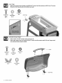
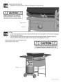
Shelves
[] insertmounting bracketsintoshelfsupportswith#10=24xl/2"screws(A).
[] Attachmounting bracketsto frontof legwith#10-24x1/2"screws=Backoflegwith#10°24×14/#'screwand
#10-24nuts (8).
NOTE:Rightshelfhasthetool holder.
#10-24x1-1/4"
Screw
Qty:4
#10-24xl/2"
Screw
Qty:12
#10-24Nut
Qty:4
A
ShelfSupport
MountingBracket
Shelf
1
463720607•463720807• 19

LowerHinges
[] Attachlowerhingesto back of firebox using#10°24xl/2"screws,5ramfiber washersand#10-24nuts.Thecenter
fiat portionof the hingeshouldbeatthe bottom(seeinset).
#10-24x1/2"
Screw
Qty:4
5mm
FiberWasher
Qty:8
@
#10-24Nut
Qty:4
LowerHinge
LidHandleand UpperHinges
[] Attachhandleto lidwith7rnmfiber washersand wingnuts.
[] Attachupperhingesto backof lidusing#10°24×1/2"screws,5ramfiber washersand#10-24nuts.Hingesshould
curvedownwardwhenproperlyinstalled.
O
#10-24Nut
Qty:4
#10-24xl/2" 5ram i
Screw FiberWasher _ ,_
Qty:4 Qty:8 ,_,
Handle
#10-24WingNut
Qty:2
7mm
FiberWasher
Qty:4
UpperHinge
20 • 463720607 • 463720807
Page is loading ...
Page is loading ...
Page is loading ...
Page is loading ...
Page is loading ...
Page is loading ...
Page is loading ...
Page is loading ...
-
 1
1
-
 2
2
-
 3
3
-
 4
4
-
 5
5
-
 6
6
-
 7
7
-
 8
8
-
 9
9
-
 10
10
-
 11
11
-
 12
12
-
 13
13
-
 14
14
-
 15
15
-
 16
16
-
 17
17
-
 18
18
-
 19
19
-
 20
20
-
 21
21
-
 22
22
-
 23
23
-
 24
24
-
 25
25
-
 26
26
-
 27
27
-
 28
28


Kenmore 640-106145-113 Owner's manual
- Category
- Barbecues & grills
- Type
- Owner's manual
- This manual is also suitable for
Ask a question and I''ll find the answer in the document
Finding information in a document is now easier with AI
Related papers
-
Char-Broil 640-174667113 Owner's manual
-
Kenmore 640-775957-111 Owner's manual
-
Kenmore 464722309 - 2 Burner Gas Grill User manual
-
-
-
-
-
-
Charbroil 463612009 Owner's manual
-
Other documents
-
Char-Broil 463820208 Owner's manual
-
Char-Broil Quickset Traditional User manual
-
-
-
-
-
-
-
-