Page is loading ...

Page 1
DIRECT
-
VENT ZERO
CLEARANCE GAS FIREPLACE
HEATER MODEL SERIES:
MILLIVOLT (MV)
DVCD(36,42)FP3(0,1)K(N,P)-4
INTERMITTENT PILOT (IP)
DVCD(36,42)FP7(0,1)K(N,P)-4
INSTALLER:
Leave this manual with the appliance.
CONSUMER:
Retain this manual for future reference.
WARNING
FIRE OR EXPLOSION HAZARD
Failure to follow safety warnings exactly
could result in serious injury, death, or
property damage.
— Do not store or use gasoline or other
ammable vapors and liquids in the
vicinity of this or any other appliance.
— WHAT TO DO IF YOU SMELL GAS
• Do not try to light any appliance.
• Do not touch any electrical switch;
do not use any phone in your building.
• Leave the building immediately.
• Immediately call your gas supplier
from a neighbor’s phone. Follow
the gas supplier’s instructions.
• If you cannot reach your gas
supplier, call the re department.
— Installation and service must be
performed by a qualied installer,
service agency or the gas supplier.
This appliance may be installed in an aftermarket,
permanently located, manufactured home (USA
only) or mobile home, where not prohibited by
local codes.
This appliance is only for use with the type of gas
indicated on the rating plate. This appliance is
not convertible for use with other gases, unless
a certied kit is used.
This replace is design
certied in accordance
with American National
Standard/CSA Standard
ANSI Z21.88/CSA 2.33
and by Underwriters
Laboratories as a Direct
Vent Gas Fireplace
Heater and shall be
installed according to
these instructions.
GAS-FIRED
UL FILE NO. MH30033
HOT GLASS
DO NOT TOUCH
NEVER
WILL
CAUSE BURNS.
GLASS
UNTIL COOLED.
ALLOW CHILDREN
TO TOUCH GLASS.
DANGER
A barrier designed to reduce the risk of burns from the
hot viewing glass is provided with this appliance and shall
be installed for the protection of children and other at-risk
individuals.
INSTALLATION INSTRUCTIONS

41394-0-0120Page 2
TABLE OF CONTENTS
Before You Start ........................................................................................................................................................... 3
Carton Contents & Hardware Pack .............................................................................................................................. 4
Homeowner Reference Information ............................................................................................................................. 5
Introduction .................................................................................................................................................................. 5
Specications ............................................................................................................................................................... 6
Accessories .................................................................................................................................................................. 6
Vent System Identication ............................................................................................................................................ 7
Special Vent Systems .................................................................................................................................................. 7
Fireplace Dimensions ................................................................................................................................................ 8-9
Clearances ................................................................................................................................................................. 10
Locating Fireplace .......................................................................................................................................................11
Gas Supply ................................................................................................................................................................. 12
Junction Box Wiring (for Optional Blower) ................................................................................................................. 14
Installation ............................................................................................................................................................. 14-16
Vent Pipe Clearance ............................................................................................................................................. 16-18
Venting Fireplace - Top .......................................................................................................................................... 19-23
Venting Fireplace - Rear ....................................................................................................................................... 24-25
Rear Vent Conversion ................................................................................................................................................ 26
Vent Clearances ......................................................................................................................................................... 27
Framing and Finishing ........................................................................................................................................... 28-29
Termination Clearances ............................................................................................................................................. 30
Horizontal Termination ................................................................................................................................................ 31
Vertical Termination ............................................................................................................................................... 32-33
DVVK-4F Flex Vent Instructions ............................................................................................................................ 34-35
DVVK-4RE Vent Kit Installation ............................................................................................................................. 36-38
Log Identication for DVCD36 Fireplaces .................................................................................................................. 39
Log Placement for DVCD36 Fireplaces ................................................................................................................ 40-47
Log Identication for DVCD42 Fireplaces .................................................................................................................. 48
Log Placement for DVCD42 Fireplaces ................................................................................................................ 49-57
Millivolt Operating Instructions .............................................................................................................................. 58-59
Millivolt Standing Pilot Wiring Diagram ...................................................................................................................... 60
Millivolt Standing Pilot Lighting Instructions ............................................................................................................... 61
Millivolt Standing Pilot Troubleshooting ...................................................................................................................... 62
IPI Electronic System Operating Instructions ............................................................................................................. 63
IPI Electronic System Wiring Diagram ....................................................................................................................... 64
Intermittent Pilot Lighting Instructions ........................................................................................................................ 65
Intermittent Pilot Control System Troubleshooting ................................................................................................ 66-68
Maintenance & Service - Qualied Service Person .............................................................................................. 69-71
DVCD36FP(3,7) Parts List ......................................................................................................................................... 72
DVCD36FP(3,7) Parts View ....................................................................................................................................... 73
DVCD42FP(3,7) Parts List ......................................................................................................................................... 74
DVCD42FP(3,7) Parts View ....................................................................................................................................... 75
Important Safety Information ...................................................................................................................................... 76
Safety Information for Users of Propane Gas ............................................................................................................ 77
Requirements for Massachusetts ............................................................................................................................... 78
Master Parts Distributor List ....................................................................................................................................... 79
How To Order Repair Parts ........................................................................................................................................ 79
Warranty ..................................................................................................................................................................... 80
Appliance Service History ..................................................................................................................................... 81-83
SECTION PAGE

41394-0-0120 Page 3
Samples and Denitions:
DANGER
Indicates a hazardous situation which, if not avoided, will
result in death or serious injury.
WARNING
Indicates a hazardous situation which, if not avoided, could
result in death or serious injury.
CAUTION
Indicates a hazardous situation which, if not avoided, could
result in minor or moderate injury.
NOTICE: Addresses practices not related to personal injury.
Read all instructions before starting installation and follow them
carefully to insure safety. Failure to follow the instructions will
void the warranty and may cause a re hazard.
The warranty will be voided by, and the warranter disclaims any
responsibility for the following actions:
• Installation of any damaged replace or vent system
component.
• Modication for the replace or direct vent system.
• Installation other than as instructed by Empire Comfort
Systems.
• Improper positioning of logs, glass door, or decorative
accessories.
• Installation and/or use of any component part not
manufactured or approved by Empire Comfort Systems.
All correspondence should refer to complete Model Number,
Serial Number and type of gas. Fill out the Homeowner
Reference Section on page 5.
Television Considerations
Installing a television above a replace has become increasingly
popular; however, the area above any replace gets hot and most
TV manufacturers recommend against placing their products
near a heat source.
If you install a television above this replace, Empire Comfort
Systems accepts no responsibility for damage or injuries. Follow
the television manufacturer’s installation instructions, including
any recommendations regarding proximity to heat sources.
If you have a TV above your replace, turn off the replace and
let it cool completely before servicing or touching any buttons on
the TV.
1. Determine where to install the replace. See page 11.
2. Frame the opening. See pages 14 - 15.
3. Install the replace. See page 15.
4. Install the venting. See pages 17 - 38.
5. Install and connect the gas lines. See pages 12 - 13.
6. Install the wiring. See pages 14, 60 and 64.
7. Light the replace. See pages 61 and 65.
8. Troubleshoot issues. See pages 62 and 66 - 68.
9. Place the serial number sticker located in the instruction
envelope onto the Service History Section.
BEFORE YOU START
10. Show the homeowner where the rating plate and lighting
instruction plate are located. See Figure 1.
11. Show the homeowner how to operate the replace.
12. Show the homeowner how to do the basic maintenance.
13. Read the safety information pages 76 - 77.
14. If located in the Commonwealth of Massachusetts, note the
special requirements on page 78.
Unpacking the replace
1. Cut binding straps and shrink wrap.
2. Remove the top of the carton.
3. Carefully remove the carton contents.
4. Use the Carton Contents and Hardware Pack lists on page 4
to verify all components are present.
5. Verify that the replace and components have not been
damaged during shipping.
6. Set replace in a location near to its nal installation location.
Preparation
This replace and its components are safe when installed in
accordance with this Installation Manual. Report any parts
damaged in shipment to your dealer. Do not install the replace
with damaged, incomplete or substitute parts.
Installation Considerations
• Gas supply piping – right or left side entrance
• Electrical supply and connections – for optional fan kit
• 120V, 60Hz, 1 Amp
• Right side entrance
• Allowable replace mounting surfaces:
• A at, hard, combustible or non-combustible surface
• A raised platform of combustible or non-combustible
material.
• The four corners of the replace onto non-combustible
material so that contact is made on all four corners of
the bottom of the replace – such as on cinder blocks
(where allowed by local codes).
• If the replace is installed directly on carpeting, tile or other
combustible material other than wood ooring, it should be
installed on a metal or wood panel extending the full width
and depth of the replace.
• This replace is designed to be installed in a zero-clearance
enclosure. Combustible material can come in contact with
the top and side standoff spacers, and the replace can be
secured to combustible framing with the framing brackets
provided with the replace.
VALVE
RATING
PLATE
LIGHTING
INSTRUCTION
PLATE
Figure 1

41394-0-0120Page 4
CARTON CONTENTS & HARDWARE PACK
LOG SET
LOG SET
Decorative
Rock
Rockwool
Rockwool
1
2
3
4
6
5
7
10
9
11
8
13
12
Index Number Description
Quantity Supplied
Location
MV IP
1 Fireplace 1 1 Between carton caps
2 Canopy 1 1 Above window door
3 Log Set 1 1 Inside rebox
4 Barrier Screen 1 1 Mounted on replace
5 Flex Line w/Shut-off Valve 1 1 In envelope
6 Decorative Rock 1 1 Under log set
7 Rockwool 2 2 In envelope
8 3-prong Receptacle 1 1 In envelope
9 Receptacle Cover 1 1 In envelope
10 AC Power Adapter 0 1 In envelope
11 AA Battery 0 4 In envelope
12 Insulation Retainer Bracket 1 1 In envelope
13 Flue Insulation 1 1 Inside rebox
NOTE: Items 12 and 13 are used only if venting from the rear of the replace. Discard if venting from the top.
#10 X ½” HEX HEAD SCREW (QTY. 8)
NAILING FLANGES (QTY. 4)
#8-18 X BLACK (QTY. 2)½” PAN HEAD SCREW

41394-0-0120 Page 5
INTRODUCTION
The information in this manual pertains to all models and gas
control systems unless otherwise noted.
Instructions to Installer
1. Leave this manual with Homeowner.
2. Have the homeowner complete the Product Registration
Card supplied with the replace; or register online at
www.empirecomfort.com
3. Show the homeowner how to start and operate the replace.
Notes to Installer
• This replace is designed to:
• Operate with combustion air siphoned from outside of
the building.
• Expel all exhaust gases to the outside of the building.
• The installation must conform with local codes or, in the
absence of local codes, with the National Fuel Gas Code
ANSI Z223.1/NFPA 54* Natural Gas and Propane Installation
Code, or CSA B149.1 in Canada. * Available from the
American National Standards Institute, Inc. 11 West 42nd
St., New York, N.Y. 10036
• Any alteration of the original design, installation other than
as shown in these instructions, or use with a type of gas not
shown on the rating plate is the responsibility of the person
and company making the change.
• This replace is not for use with solid fuels.
• These replace models may be installed in a bedroom or
bed-sitting room in the U.S.A. and Canada.
WARNING
Any change to this replace can be dangerous. Improper
installation or use of the rebox can cause serious injury
or death from re, burns, explosion or carbon monoxide
poisoning.
Fireplace Certication
This replace is design certied in accordance with American
National Standard/CSA Standard ANSI Z21.88/CSA 2.33 and by
Underwriters Laboratories as a Direct Vent Gas Fireplace Heater
and shall be installed according to these instructions.
Consult your local building code agency, prior to installation,
to ensure compliance with local codes-including permits and
inspections.
The replace, when installed, must be electrically grounded in
accordance with local codes or, in absence of local codes, with
the National Electric Code ANSI/NFPA 70 or Canadian Electric
code, CSA C22.1, if an external electrical source is utilized.
Qualied Installing Agency
Installation and replacement of gas piping, gas utilization
equipment or accessories and repair and servicing of equipment
shall be performed only by a qualied agency. The term “qualied
agency” means any individual, rm, corporation or company
which either in person or through a representative is engaged
in and is responsible for (a) the installation or replacement of
gas piping or (b) the connection, installation, repair or servicing
of equipment, who is experienced in such work, familiar with all
precautions required and has complied with all the requirements
of the authority having jurisdiction.
Commonwealth of Massachusetts: The installation must be
made by a licensed plumber or gas tter in the Commonwealth
of Massachusetts.
High Altitude
When installing this replace at an elevation above 2000 feet (in
the United States) it may be necessary to decrease the input rating
by changing the existing burner orice to a smaller size. Generally,
input should be reduced 4 percent for each 1000 feet above sea
level. However, if the heating value of the gas has been reduced,
this general rule may not apply. Check with EMPIRE COMFORT
SYSTEMS for proper orice size identication.
Canadian High Altitude
Altitude: 0-4500 feet (0-1370 m)
When installing this replace at an elevation above 4500 feet
(in Canada), check with local authorities.
Consult your local gas utility for assistance in determining the
proper orice for location.
HOMEOWNER REFERENCE INFORMATION
We recommend that you record the following information about your replace.
Model Number: _____________________________ Date purchased: ________________________
Serial Number: _____________________________ Location of replace: _____________________
Dealer Name: ______________________________ Dealer Phone: _________________________
Notes: ______________________________________________________________________________

41394-0-0120Page 6
ACCESSORIES
The following accessories are available from your Empire Dealer.
ACCESSORIES
Description Model
Ember Bed Kit EK1
Platinum Glowing Embers PE20
Variable Speed Blower FBB4
Flex Gas Line, 24-in
Stainless Steel
GF24
NOTICE: Empire Comfort Systems does not offer a mantel for
this series of replaces.
CONTROL OPTIONS
Description Model
Battery Remote, On/OFF FRBC
Battery Remote, Thermostat FRBTC
Remote, Electric FREC
Remote, Programmable FRBTP
Wall Switch, On/Off FWS1
Wall Thermostat – Reed Switch TMV
Wall Thermostat – Wireless TRW
VENT KITS
Part No. Description
DVVK4TSP
Top Vent Kit (horizontal) – 4-1/2 to 6-inch wall
thickness
DVVK4TP
Top Vent Kit (horizontal) – 8 to 12-inch wall
thickness
DVVK4RP
Rear Vent Kit (horizontal – 5 to 7-inch wall
thickness
DVVK4VP Vertical Vent Kit
DVVK4F Horizontal Flex Vent Kit (4-foot ex)
DVVK4RE
Horizontal round termination (wall thickness up
to 13-3/4 inches)
DV822 Vinyl Siding Kit for DVVK-4RE
CONVERSION KITS
Kit # Conversion Type Used On
18817 Propane to Natural DVCD36FP3
18442 Natural to Propane DVCD36FP3
18818 Propane to Natural DVCD42FP3
18814 Natural to Propane DVCD42FP3
31759 Propane to Natural DVCD36FP7
32882 Natural to Propane DVCD36FP7
31761 Propane to Natural DVCD42FP7
31760 Natural to Propane DVCD42FP7
SPECIFICATIONS
DVCD36
Natural Gas
DVCD36
Propane Gas
DVCD42
Natural Gas
DVCD42
Propane Gas
Input BTU/Hr Maximum 20,000 20,000 25,000 25,000
Input BTU/Hr Minimum 14,000 16,500 18,000 19,500
KWH Maximum 5.9 5.9 7.3 7.3
KWH Minimum 4.1 4.1 5.3 5.3
Orice 2.10mm #55 (0.052 inch) #42 (0.0935 inch) 1.45mm
Air Shutter Opening (inches) 1/16 5/16 3/16 5/16
Gas Inlet Shutoff Valve (pipe) 1/2 NPT 1/2 NPT 1/2 NPT 1/2 NPT
NOTICE: Air shutter settings are factory minimum settings. Some venting congurations may require minor air shutter adjustments for
optimum performance.
GAS SUPPLY PRESSURES (inches water column)
Gas Type Maximum Minimum Manifold
Natural 14.0 4.5 3.5
Propane 14.0 10.5 10.0

41394-0-0120 Page 7
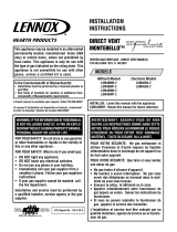
CEILING FIRE STOP
90° ELBOW
90° ELBOW
OR
45° ELBOW
WALL STRAP
PIPE LENGTH
WALL THIMBLE
HORIZONTAL
TERMINATION
(MAXIMUM OF
THREE 90° ELBOWS)
VERTICAL
TERMINATION
(MAXIMUM OF
THREE 90° ELBOWS)
STORM COLLAR
ROOF FLASHING
Figure 2
VENT SYSTEM IDENTIFICATION
Begin the vent system installation by selecting the type of venting
to be installed and the path that it will take. Verify that clearances
are met throughout the path of the venting system. Determine if
the replace is to be vented out the top.
Special venting components
See Empire Comfort Systems Retail Price List for Duravent part
numbers and pricing.
Special DV Vent Kits
Available from Empire Comfort Systems Dealers
DVVK-4VP
Direct-Vent Fireplace Vent Kit - Vertical,
Includes
46DVA-VCH, 46DVA-F6 and 46DVA-SC
DVVK-4TP
Direct-Vent Fireplace Vent Kit for Top Vent,
Thru-the-wall, 8 to 11 inch wall thickness,
Includes 46DVA-HC, 46DVA-E90, 46DVA-09,
46DVA-08A and 46DVA-WT
DVVK-4RP
Direct-Vent Fireplace Vent Kit for Rear Vent,
5 to 7 inch wall thickness, (standard thru-the-
wall venting) includes 46DVA-06, 46DVA-HC
and 46DVA-WT
DVVK-4RE
Direct-Vent Fireplace Vent Kit For Rear
Vent, Thru-the-wall for 5 to 13 3/4 inch wall
thickness.
DVVK-4TSP
Direct-Vent Fireplace Vent Kit for Top Vent,
Thru-the-wall, 5 to 7 inch wall thickness,
Includes 46DVA-HC, 46DVA-E90, 46DVA-06
and 46DVA-WT
DVVK-4FV Vertical Flex Vent Kit 4 x 7 inch
VIB6A
Vertical Inlet Bafe Kit For 6-5/8 inch diameter.
VIB7A Vertical Inlet Bafe Kit For 7 inch diameter.
NOTICE: Additional pipe may be required for proper venting.
Determine how the vent system will be terminated out the side
of the house or through the roof. Verify the clearances for the
termination.
SPECIAL VENT SYSTEMS
The following 4 x 6-5/8 inch vent systems are acceptable for use with the DVCD(36,42)FP series replaces:
• Duravent® Pro
• American Metal Products
• Selkirk Direct-Temp®
• Security Secure Vent®
• Excel DV Venting
• Olympia VENTIS®
• Metal Fab Sure Seal®
– Adapter is required to use this vent
Contact Metal Fab
• BDM
• Empire Horizontal Round Termination Kit DVVK-4RE
• Empire Flexvent Kit DVVK-4F
• Empire Flexvent Kit DVVK-4FV Vertical Flex Vent Kit

41394-0-0120Page 8
Figure 3
FIREPLACE DIMENSIONS
G
I1
J1
P1
TOP VENTING
LEFT VIEW
C
O
N
S
E
B
D
Q
FRONT VIEW
T
K
L
M
RIGHT VIEW
Z
X
Y
REAR VENTING
P2
J2
I2
CORNER INSTALL
H
A
R

41394-0-0120 Page 9
FIREPLACE DIMENSIONS
SIDE STANDOFF
INSTALLED NAILING
FLANGES
GAS LINE
ACCESS
BARRIER SCREEN ASSEMBL
Y
&
GLASS FRAME ASSEMBLY
VENT COLLAR
GAS CONTROL AND
SWITCHES INSIDE
RATING PLATE AND
LABELS INSIDE
TOPSTANDOFF
Figure 4
INDEX
LETTER
DIMENSION DESCRIPTION
DVCD36 DVCD42
Dimensions in Inches
A The maximum height of rebox face (excluding standoffs) 35-5/8 37-5/8
B The maximum width of the rebox face (excluding nailing anges) 37-9/16 43-9/16
C The maximum depth of the rebox 17-3/4 17-3/4
D The height of the rebox opening 27-1/2 29-1/2
E The width of the rebox opening 34 40
F The interior depth of the rebox 11-1/2 11-9/16
G The rear exterior width of the rebox (not shown) 24-9/16 30-9/16
H The height of the rebox standoffs 6 6
I1 Width from the left side of the box to the centerline of top vent 18-13/16 21-13/16
I2 Width from the right side of the box to the centerline of rear vent 18-13/16 21-13/16
J1 Depth from back of box to centerline of top vent 7 7
J2 Distance from top of standoff to centerline of rear vent 14-3/16 14-3/16
K Height from the bottom of the box to the gas line opening 2-1/16 2-1/16
L Depth from the front of the box to gas line opening 10 10
M Depth from rear of box to gas line opening 6 6
N Glass height 20 22
O Glass width 30-1/2 36-1/2
P1 Depth from front of box to centerline of top vent 10-3/4 10-3/4
P2 Distance from bottom of replace to centerline of rear vent 24-3/8 26-3/8
Q Distance from oor to replace opening 1-3/16 1-3/16
R Height from oor to vent collar 35-9/16 37-5/8
S Overall height to header 38-3/4 40-3/4
T Weight from oor to top of canopy 30-3/8 32-3/8
X Corner installation depth 29-11/16 32-5/8
Y Corner installation width 59-3/8 65-1/4
Z Corner installation wall length 41-7/8 46-1/8

41394-0-0120Page 10
CLEARANCES
CLEARANCE TO COMBUSTIBLES
DIM. IN INCHES
Back 0
Side 0
Floor 0
Top Stand-off
0
Top Framing Edge 0
BARRIER SCREEN
&
GLASS FRONT
2" x 4" BOTTOM PLATE
INSTALLED
NAILING
FLANGES
STAND OFF
6” (76mm) HEIGHT
ABOVE TOP OF
FIREPLACE
FINISHED WALL
(COMBUSTIBLE)
SEE MANTEL CHART FOR
MAXIMUM MANTEL DEPTH
SEE MANTEL CHART FOR
MINIMUM HEIGHT OF
MANTEL ABOVE HOOD
FINISHED WITH
NON-COMBUSTIBLE
MATERIAL AS DESIRED
Figure 5
NOTICE: If applicable, use only non-combustible materials to
nish the face of the replace.
Combustible Material
No greeting cards, stockings or ornamentation of any type should
be placed on or attached to the replace or its mantel. The ow of
heat can ignite combustibles.
FIREPLACE
(TOP VIEW)
FRONT
FACE
(SIDE)
COMBUSTIBLE
MATERIALS ALLOWED
IN SHADED AREAS
3
MAX.
6
PERPENDICULAR
SIDE WALL
45°
HOOD
Figure 6
Mantel Chart
CANOPY
FIREBOX
FACE
84”
MIN.
(CEILING TO FLOOR)
CEILING
FLOOR
WALL
FACING
A
B
C
D
E
F
10”
20 1/4”
MIN.
10 1/4”
MIN.
41”
MIN.
COMBUSTIBLES
ALLOWED
WALL
STUD
TOP OF CANOPY
INDEX
LETTER
DISTANCE FROM
WALL FACING
DISTANCE FROM
TOP OF CANOPY
Dimensions in inches
A 2 10-1/4
B 4 12-1/4
C 6 14-1/4
D 8 16-1/4
E 10 18-1/4
F 12 20-1/4
Figure 7
Clearances
Clearance from top of canopy of replace to ceiling is 41 inches.
Clearance from side of replace to adjacent sidewall is 6 inches.
41” (91.4 mm)
MINIMUM
6” (152 mm)
MINIMUM
Figure 8

41394-0-0120 Page 11
Figure 9
NOTICE: Island and room divider installation are possible as long as the horizontal portion of the vent system does not exceed 20 feet
with a minimum vertical run of 8 feet. Refer to Venting Section (pages 16 - 27).
Maintain a minimum 6-inch clearance to the perpendicular wall from the front edge of the replace.
LOCATING FIREPLACE

41394-0-0120Page 12
GAS SUPPLY
The gas pipeline can be brought in through left or right side of
the replace. Consult the current National Fuel Gas Code, ANSI
Z223.1 CAN/CGA-B149 (.1 or .2) installation code.
GAS LINE HOLE
(BOTH SIDES)
10”
2”
FROM FRONT OF
FIREPLACE TO
GAS LINE HOLE
Figure 10
RECOMMENDED GAS PIPE DIAMETER
Pipe
Length
Schedule 40 Pipe
Inside Diameter
Tubing, Type L
Outside Diameter
Natural Propane Natural Propane
(Dimensions in inches)
0-10 feet 1/2 3/8 1/2 3/8
10-40 feet 1/2 1/2 5/8 1/2
40-100 feet 1/2 1/2 3/4 1/2
100-150 feet 3/4 1/2 7/8 3/4
NOTICE: Check to conrm whether your local codes allow
copper tubing or galvanized.
NOTICE: Because some municipalities have additional local
codes, consult your local authority and installation code.
The use of the following gas connectors is recommended:
— ANSI Z21.24 Appliance Connectors of Corrugated Metal
Tubing and Fittings.
— ANSI Z21.45 Assembled Flexible Appliance Connectors of
Other Than All-Metal Construction
The above connectors may be used if acceptable by the authority
having jurisdiction. The Commonwealth of Massachusetts
requires that a exible appliance connector cannot exceed three
feet in length.
FLEXIBLE GAS LINE CONNECTION
GAS SUPPLY
TEE HANDLE
FLEX TUBING
FLARE FITTING FLARE SHUT
OFF VALVE
Figure 11
Install a gas valve and ground joint union in the gas line upstream
of the gas control to aid in servicing. The National Fuel Gas
Code requires installing a drip leg near the gas inlet. The drip
leg consists of a vertical length of capped pipe installed before
the gas inlet to collect condensation and foreign particles. See
Figure 12.
GAS SUPPLY PIPING
SHUT-OFF VALVE
GAS SUPPLY
INLET
1/8 NPT PLUGGED HOLE
FOR TEST GAGE
3” MINIMUM
GROUND JOINT UNIO
N
DRIP LEG
CAP
Figure 12

41394-0-0120 Page 13
GAS SUPPLY (CONT’D)
Installing a New Main Gas Supply Shut-off Valve (Check
Local Code)
Each appliance must have its own manual gas shut-off valve
located in the vicinity of the replace. Where none exists, or
where its size or location is not adequate, contact your local
authorized installer for replacement or relocation.
Test for leaks. Turn replace off. Compounds used on threaded
joints of gas piping must be resistant to the action of liqueed
petroleum gases. The installer must check all gas connections
for leaks. Perform all leak tests with a leak test solution or soap
solution. Rinse off all solution once testing is complete. Perform a
pressure test on all unexposed connections.
Never use an exposed ame to check for leaks. Never pressure
test with replace connected; control valve will sustain damage.
Disconnect the replace from piping at the control valve inlet and
cap the pipe before pressure testing.
NOTICE: The millivolt gas controls are equipped with a captured
screw type pressure test point, therefore it is not necessary to
provide a 1/8 inch test point up stream of the control.
Use only approved ttings with copper or ex connectors.
Disconnect the replace and its individual shut-off valve from the
supply piping system during any pressure testing of that system
at test pressures in excess of 1/2 psig (3.5 kPa).
Close the replace manual shut off valve to isolate it from the
gas supply piping system during any pressure testing of the gas
supply piping system at test pressures equal to or less than
1/2 psig (3.5 kPa).
WARNING
If one of the test procedures results in pressures in excess
of 1/2 psig (14 inches w.c.) (3.5 kPa) on the replace gas
valve, it will result in a hazardous condition.
Checking Manifold Pressures
Both Propane and Natural gas valves have a built-in pressure
regulator in the gas valve. Natural gas models will have a manifold
pressure of approximately 3.5 inches w.c. (.871 kPa) at the valve
outlet with the inlet pressure to the valve from a minimum of 4.5
inches w.c. (1.120 kPa) for the purpose of input adjustment to a
maximum of 14.0 inches w.c. (3.484 kPa). Propane gas models
will have a manifold pressure of approximately 10.0 inches w.c.
(2.49 kPa) at the valve outlet with the inlet pressure to the valve
from a minimum of 10.8 inches w.c. (2.68 kPa) for the purpose of
input adjustment to a maximum of 14.0 inches w.c. (3.484 kPa).
Gas Supply Pressure (inches w.c.)
Minimum Normal Maximum
Natural Gas 4.5 7.0 14.0
Propane Gas 10.8 11.0 14.0
Manifold Pressure (inches w.c.)
Normal (HI)
Natural Gas 3.5
Propane Gas 10.0
HI/LO REGULATOR
CONTROL KNOB
OUTLET
PRESSURE
TAP
INLET
PRESSURE
TAP
Figure 13 - Millivolt Valve
OUTLET PRESSURE TAP
INLET PRESSURE TAP
Figure 14 - IP Valve

41394-0-0120Page 14
JUNCTION BOX WIRING (FOR OPTIONAL BLOWER)
CAUTION
All wiring should be done by a qualied electrician and shall
be in compliance with all local, city and state building codes.
Before making the electrical connection, make sure that the
main power supply is disconnected. The replace, when
installed, must be electrically grounded in accordance with
local codes or, in the absence of local codes, with the National
Electrical Code ANSI/NFPA 70 (latest edition).
A factory installed junction box is located on the lower right
side of the replace. Wiring must be fed to the junction box and
attached to the receptacle that is provided. Leave approximately
six inches of wire in the junction box for connection.
Attach black wire to one side of the receptacle and white wire to
opposite side of receptacle. The ground wire should be attached
to the green (ground) screw.
Install the receptacle into the junction box. Attach cover plate.
STANDARD MILLIVOLT VALVE MODELS
Figure 15
INSTALLATION
The replace can be mounted on any of the following surfaces:
1. A at, hard combustible (burnable) surface.
2. A raised wooden platform.
3. Four corner supports. (Example: Four concrete masonry
blocks.) These supports must be positioned so they contact
all four perimeter edges on the bottom of the replace, if
allowed by local codes.
NOTICE: Verify the gas supply and electrical considerations
before beginning the framing.
Framing Information
Fireplace framing can be built before or after the replace is set
in place. Posistion framing to accommodate wall covering and
replace facing material. Construct the replace framing with
2 x 4 lumber or heavier. The framing headers or top plate may
rest on the replace standoffs. Refer to Figure 16 for minimum
framing dimensions.
CAUTION
Before construction begins, measure replace dimensions
and verify framing methods and wall covering details.
HEADER
DIMENSIONS (IN INCHES)
DVCD36 DVCD42
A 39 41
B 38-1/4 44-1/4
C 18 18
Figure 16

41394-0-0120 Page 15
INSTALLATION (CONT’D)
Frame the Fireplace Opening
1. Choose replace location.
2. Frame in replace opening with a plate across the top. It is
important to allow for the nished replace face when setting
the depth of the frame.
PLATE
Figure 17
3. Bend the nailing anges 90 degrees.
NOT USED
½” BOARD
5/8”
BOARD
USED TO
AT
TACH TO
FRAMING
Figure 18
4. Attach replace to frame using adjustable nailing anges.
Set the nailing ange depth to suit the wall material
(adjustable to 1/2 or 5/8 inch).
Figure 19
5. Secure the nailing anges to the replace with #10 x ½ inch
screws (provided).
6. Secure the nailing anges to the framing with nails or other
suitable fasteners (not provided). See Figure 20.
NAIL OR OTHER SUITABLE FASTENER
Figure 20

41394-0-0120Page 16
INSTALLATION (CONT’D)
Install the Canopy
1. Retrieve canopy from the opening above the glass door.
2. Place the canopy above the rebox as shown in Figure 21.
NOTICE: Fireplace heat shield will rest on top of the combustion
chamber inside of the open area between the top ue and
canopy.
3. Secure the canopy with two #8-18 x 1/2 inch pan head
screws provided in the hardware pack. See Figure 21.
HEAT
SHIELD
CANOPY
Figure 21
NOTICE: Maintain one inch of clearance to combustibles around
vertical vent pipe. See Figure 22. For horizontal vent systems,
maintain a minimum 1-inch clearance from the bottom and sides
of the vent to combustibles and a 3-inch clearance above the
vent pipe above the vent pipe to combustibles. See Figures 23
and 24.
Cold Climate Installation Recommendation: Insulate the outer
walls to conform with applicable insulation codes if installing this
replace against a non-insulated exterior wall.
Figure 22
VENT PIPE CLEARANCE
Finishing
Figure 7 on page 10 shows the minimum vertical and
corresponding maximum horizontal dimensions of mantels or
other combustible projections above the top front edge of the
replace.
Only non-combustible materials may be used to cover the black
replace face.
WARNING
Never obstruct or modify face of the replace. Improper
installation may cause a hazardous situation.
CAUTION
A 300°F minimum sealant material must be used if the joints
between the nished wall and the replace surround (top
and sides) are sealed. These joints are not required to be
sealed. Only non-combustible material (use if needed),
can be applied to the replace surround. Consequences:
Failure to use the 300°F minimum adhesive may allow the
nishing material to fall.
NOTICE: For nishing to top of replace, refer to Figure 5, page 10.
6-5/8” Diameter
intake vent
4” Diameter flue
Combustibles NOT
allowed in shaded
area
Top of Vent
3” (76 mm)
1” (25 mm)
1”
(25 mm)
Figure 23 - Hard Pipe Vent Clearance

41394-0-0120 Page 17
11”
(297 mm)
MIN.
9 1/8”
(232 mm)
MIN.
OUTSIDE THIMBLE ASSEMBLY
INSIDE THIMBLE ASSEMBLY
EXTERIOR
SHEAVING
Figure 24
VENT PIPE CLEARANCE
Vertical, 90° Elbow with Horizontal Termination
3” (76mm)
MINIMUM CLEARANCE
TO COMBUSTIBLES
VENT CAP/
THIMBLE
WALL FIRESTOP
DVCD(32,36)
47 ½”
(121 cm)
TO BOTTOM
OF UNIT
DVCD42
49 ½”
(126 cm)
TO BOTTOM
OF UNIT
Figure 25
Horizontal Only, Straight Out the Back
“A”
PIPE LENGTH
VENT CAP
WALL FIRESTOP/
THIMBLE
“B”
DIMENSIONS (INCHES)
Models
A B
6 5-1/8 to 6-1/2 DVCD(36,42)
9 8-1/8 to 9-1/2 DVCD(36,42)
12 11-1/8 to 12-1/2 DVCD(36,42)
Figure 26

41394-0-0120Page 18
Vertical, 90° Elbow to Horizontal Out the Wall
90° ELBOW
“A”
PIPE
LENGTH
VENT CAP
WALL FIRESTOP/
THIMBLE
“B”
“C”
DIMENSIONS (INCHES)
A B C
6 11-1/4 to 12-3/4 4-3/4 to 6-1/4
9 14-1/4 to 15-3/4 7-3/4 to 9-1/4
12 17-1/4 to 18-3/4 10-3/4 to 12-1/4
Figure 27
Corner Installation Vertical, 90° Elbow to Horizontal Out the
Wall
WALL FIRESTOP/
THIMBLE
VENT
CAP
6” (152 mm)
MINIMUM
9” (229 mm)
MINIMUM
“B”
“C”
Dimensions (inches)
B C
DVCD36 DVCD42 DVCD(36,42)
18-1/16 to 19-9/16 20-3/16 to 21-11/16 4-3/4 to 6-1/4
21-1/16 to 22-9/16 23-3/16 to 24-11/16 7-3/4 to 9-1/4
24-1/16 to 25-9/16 26-3/16 to 27-11/16 10-3/4 to 12-1/4
Figure 28
Corner Installation Horizontal, 45° Elbow to Horizontal Out
the Wall
WALL FIRESTOP/
THIMBLE
“A”
PIPE LENGTH
VENT CAP
“B”
Reference Letter
DVCD36 DVCD42
Dimension (inches)
A B B
6 4 to 5 N/A
9 6 to 7-1/2 4 to 5-1/2
12 9 to 10-1/2 9 to 10-1/2
Figure 29
VENT PIPE CLEARANCE

41394-0-0120 Page 19
To Use the Vent Graph
1. Determine the height of the center of the horizontal vent pipe.
Using this dimension on the Sidewall Vent Graph, locate the
point it intersects with the slanted graph line.
2. From the point of this intersection, draw a vertical line to the
bottom of the graph.
3. Select the indicated dimension, and position the unit in
accordance with same.
EXAMPLE A:
If the vertical dimension from the oor of the unit is 35 feet, the
horizontal run to the outer wall ange must not exceed 6.5 feet.
EXAMPLE B:
If the vertical dimension from the oor of the unit is 6.5 feet, the
horizontal run to the outer wall ange must not exceed 14.5 feet.
SPECIAL NOTE: For each 45 degree elbow installed in the
horizontal run, the length of the horizontal run MUST be reduced
by 18" (457 mm). This does not apply if the 45 degree elbows
are installed on the vertical part of the vent system. Reduce 3'
for every 90° elbow.
Example: According to the chart the maximum horizontal vent
length is 20' and if two 45 degree elbows are required in the
horizontal vent it must be reduced to 17'.
The maximum number of 45 degree elbows permitted per side
wall installation is two (2). These elbows can be installed in either
the vertical or horizontal run.
NOTICE: The rst elbow off the top of the replace is gured
into the chart.
Acceptable vertical and horizontal vent run.
(40' maximum vertical and 20' maximum horizontal)
Unacceptable vertical and horizontal vent run.
Figure 30
Venting Graph (Dimensions in Feet)
TOP EXIT - VERTICAL AND HORIZONTAL TERMINATION
(DIMENSIONS IN FEET)
VERTICAL DIMENSION FROM THE BOTTOM OF THE UNIT TO THE CENTER OF THE
FLUE OUTLET WITH VERTICAL OR HORIZONTAL TERMINATION CAPS
TO
P VENT
CONNECTION
(HEIGHT
MAY
VA
RY WITH
MODEL)
HORIZONTAL RUN
VENTING FIREPLACE - TOP

41394-0-0120Page 20
VENTING FIREPLACE - TOP
Example of possible venting systems using one 90° elbow.
Eight feet is listed as minimum vertical vent run with 20 feet of
maximum horizontal vent run. Vertical dimensions are based on
centerline to centerline of pipe. Horizontal dimensions are based
on centerline of pipe to end of termination.
SEE GRAPH FOR PERMISSIBLE “H” AND “V” DIMENSIONS
FIRESTOP AT
CEILING LEVEL
IF PENATRATING
CEILING
H
V
Figure 32
Below Grade Installation
Empire recommends installing a snorkel kit when it is not
possible to meet the required vent terminal clearances of
12 inches (305 mm) above grade level. A snorkel kit allows an
installation depth down to 7 inches (178 mm) below grade level.
The 7 inches (178 mm) is measured from the center of the
horizontal vent pipe as it penetrates through the wall.
Ensure the sidewall venting clearances are observed.
Empire recommends installing a window well with adequate
and proper drainage around the termination area if the
venting system is installed below ground.
3” (76mm)
MINIMUM
PIPE STRAP
48”
(1219mm)
COMBUSTIBLE
PROJECTION
18” (457mm)
MINIMUM
12” (305mm)
ABOVE GRADE OR
EXPECTED SNOW LEVEL
TYPICAL BASEMENT INSTALLATION
Figure 31
ATTENTION
Vinyl Soft, Vinyl Ceiling, Vinyl Overhang Disclaimer
Clearances are to heat resistant material (i.e. wood, metal). This
does not include vinyl. Empire Comfort Systems will not be held
responsible for heat damage caused from terminating under vinyl
overhangs, vinyl ceilings or vinyl ventilated/unventilated softs.
/