Ethernet [Modbus/TCP] Communication Converter
IMR01Y48-E1
Thank you for purchasing this RKC product. In order to achieve maximum performance and
ensure proper operation of the instrument, carefully read all the instructions in this manual.
Please place the manual in a convenient location for easy reference.
This manual describes the mounting, wiring and specifications only.
Product check
Safety precautions
This product is intended for use with industrial machines, test and measuring equipment.
(It is not designed for use with medical equipment and nuclear energy plant.)
This is a Class A instrument. In a domestic environment, this instrument may cause radio
interference, in which case the user may be required to take additional measures.
This instrument is protected from electric shock by reinforced insulation. Provide reinforced
insulation between the wire for the input signal and the wires for instrument power supply,
source of power and loads.
Be sure to provide an appropriate surge control circuit respectively for the following:
If input/output or signal lines within the building are longer than 30 meters.
If input/output or signal lines leave the building, regardless the length.
This instrument is designed for installation in an enclosed instrumentation panel. All
high-voltage connections such as power supply terminals must be enclosed in the
instrumentation panel to avoid electric shock to operating personnel.
All precautions described in this manual should be taken to avoid damage to the instrument
or equipment.
If the equipment is used in a manner not specified by the manufacturer, the protection
provided by the equipment may be impaired.
All wiring must be in accordance with local codes and regulations.
To prevent instrument damage as a result of failure, protect the power line and the
input/output lines from high currents with a suitable overcurrent protection device with
adequate breaking capacity such as a fuse, circuit breaker, etc.
A malfunction in this product may occasionally make control operations impossible or
prevent alarm outputs, resulting in a possible hazard. Take appropriate measures in the
end use to prevent hazards in the event of malfunction.
Prevent metal fragments or lead wire scraps from falling inside instrument case to avoid
electric shock, fire or malfunction.
For proper operation of this instrument, provide adequate ventilation for heat dissipation.
Do not connect wires to unused terminals as this will interfere with proper operation of the
instrument.
Turn off the power supply before cleaning the instrument.
Do not use a volatile solvent such as paint thinner to clean the instrument. Deformation or
discoloration may occur. Use a soft, dry cloth to remove stains from the instrument.
NOTICE
This manual assumes that the reader has a fundamental knowledge of the principles of
electricity, process control, computer technology and communications.
The figures, diagrams and numeric values used in this manual are only for explanation
purpose.
RKC is not responsible for any damage or injury that is caused as a result of using this
instrument, instrument failure or indirect damage.
RKC is not responsible for any damage and/or injury resulting from the use of instruments
made by imitating this instrument.
Periodic maintenance is required for safe and proper operation of this instrument. Some
components have a limited service life, or characteristics that change over time.
Every effort has been made to ensure accuracy of all information contained herein. RKC
makes no warranty, expressed or implied, with respect to the accuracy of the information.
The information in this manual is subject to change without prior notice.
No portion of this document may be reprinted, modified, copied, transmitted, digitized,
stored, processed or retrieved through any mechanical, electronic, optical or other means
without prior written approval from RKC.
Various symbols are used on the equipment, and they have the following meaning.
: Direct current
: Reinforced insulation
: Safety precaution
This symbol is used where the instruction manual needs to be consulted for the safety
of both the operator and the equipment. Carefully read the cautions in this manual
before using the instrument.
1. MOUNTING
1.1 Mounting Cautions
(1) This instrument is intended to be used under the following environmental conditions.
(IEC 61010-1) [OVERVOLTAGE CATEGORY II, POLLUTION DEGREE 2]
(2) Use this instrument within the following environment conditions:
Allowable ambient temperature: 10 to 50 C
Allowable ambient humidity: 5 to 95 %RH
(Absolute humidity: MAX.W.C 29.3 g/m
3
dry air at 101.3 kPa)
Installation environment conditions: Indoor use,
Altitude up to 2000 m
(3) Avoid the following conditions when selecting the mounting location:
Rapid changes in ambient temperature which may cause condensation.
Corrosive or inflammable gases.
Direct vibration or shock to the mainframe.
Water, oil, chemicals, vapor or steam splashes.
Excessive dust, salt or iron particles.
Excessive induction noise, static electricity, magnetic fields or noise.
Direct air flow from an air conditioner.
Exposure to direct sunlight.
Excessive heat accumulation.
(4) Mount this instrument in the panel considering the following conditions:
Ensure at least 50 mm space on top and bottom of the instrument for maintenance and
environmental reasons.
Do not mount this instrument directly above the equipment that generates large amount
of heat (heaters, transformers, semi-conductor functional devices, large-wattage resistors.)
If the ambient temperature rises above 50 C, cool this instrument with a forced air fan,
cooler, etc. Cooled air should not blow directly on this instrument.
In order to improve safety and the immunity to withstand noise, mount this instrument as
far away as possible from high voltage equipment, power lines, and rotating machinery.
High voltage equipment: Do not mount within the same panel.
Power lines: Separate at least 200 mm.
Rotating machinery: Separate as far as possible.
For correct functioning mount this instrument in a horizontal position.
(5) In case this instrument is connected to a supply by means of a permanent connection,
a switch or circuit-breaker shall be included in the installation. This shall be in close
proximity to the equipment and within easy reach of the operator. It shall be marked as
the disconnecting device for the equipment.
1.2 Dimensions
3
30
109.5
125
78
5
(Unit: mm)
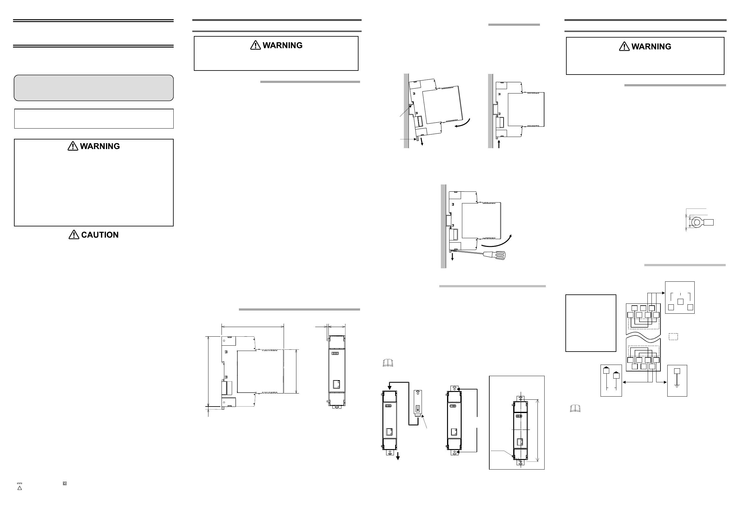
1.3 DIN Rail Mounting and Removing
Mounting procedures
1. Pull down the mounting bracket at the bottom of the module (A). Attach the hooks
on the top of the module to the DIN rail and push the lower section into place on
the DIN rail (B).
2. Slide the mounting bracket up to secure the module to the DIN rail (C).
Removal procedures
Pull down a mounting bracket with a blade screwdriver (A). Lift the module from
bottom, and take it off (B).
1.4 Panel Mounting
Mounting procedures
1. Pull down the mounting bracket (A) until locked and that a mounting hole
appears.
2.
Prepare one mounting bracket per instrument (B) sold separately (KSRX-55) and
then insert it in the rear of the terminal board at top of the instrument until locked
but a mounting hole does not disappear.
3.
Mount each module directly on the panel with screws which are inserted in the
mounting holes of the top and bottom mounting brackets.
Recommended tightening torque: 0.3 Nm (3 kgfcm)
The customer needs to provide the M3 size screws. Select the screw length
that matches the mounting panel.
(A) Pull down
(B) Insert
Mounting bracket
(Sold separately)
(KSRX-55)
Mounting
holes
Mounting dimensions
130.5 0.2
M3
(Unit: mm)
2. WIRING
2.1 Wiring Cautions
To avoid noise induction, keep communication signal wire away from instrument
power line, load lines and power lines of other electric equipment.
If there is electrical noise in the vicinity of the instrument that could affect
operation, use a noise filter.
Shorten the distance between the twisted power supply wire pitches to
achieve the most effective noise reduction.
Always install the noise filter on a grounded panel. Minimize the wiring
distance between the noise filter output and the instrument power supply
terminals to achieve the most effective noise reduction.
Do not connect fuses or switches to the noise filter output wiring as this will
reduce the effectiveness of the noise filter.
Power supply wiring must be twisted and have a low voltage drop.
For an instrument with 24 V power supply input, supply power from “SELV”
circuit defined as IEC 60950-1.
A suitable power supply should be considered in end-use equipment. The
power supply must be in compliance with a limited-energy circuits (maximum
available current of 8 A).
Use the solderless terminal appropriate to the screw size.
Screw size: M3
×6 (with 5.8×5.8 square washer)
Recommended tightening torque:
0.4 N
m [4 kgfcm]
Specified dimension:
Refer to Fig. at the right
Make sure that during field wiring parts of conductors cannot come into contact
with adjacent conductive parts.
2.2 Terminal Configuration
24 V
DC
12
9
8
FG
Controller
communication
T/R(B)
T/R(A)
RS-485
1
5
SG
4
Upper-side
terminal
Lower-side
terminal
Power supply
Ground
2 1
7 6 5 4
14 13 12
11 10 9 8
3
: The part of internal wiring
As controller communication terminal Nos. 1, 4 and 5 are internally
connected to terminal Nos. 3, 6 and 7, any terminals can be used.
As ground and power supply terminal Nos. 8, 9 and 12 are internally
connected to terminal Nos. 10, 11 and 14, any terminals can be used.
Terminal No. 2 and No. 13 is not used.
To prevent injury to persons, damage to the instrument and the
equipment, a suitable external protection device shall be required.
All wiring must be completed before power is turned on to prevent
electric shock, fire or damage to the instrument and the equipment.
This instrument must be used in accordance with the specifications to
prevent fire or damage to the instrument and the equipment.
This instrument is not intended for use in locations subject to
flammable or explosive gases.
Do not touch high-voltage connections such as power supply terminals,
etc. to avoid electric shock.
RKC is not responsible if this instrument is repaired, modified or
disassembled by other than factory-approved personnel. Malfunction
may occur and warranty is void under these conditions.
All Rights Reserved, Copyright 2017, RKC INSTRUMENT INC.
COM-JL [For SRJ] Installation Manual (IMR01Y48-E1) ........................................... 1
COM-JL [For SRJ] Quick Instruction Manual (IMR01Y49-E)
.................................. 1
COM-JL [For SRJ] Communication Data List (IMR01Y50-E) ............................... 1
!
CO
JL
Installation
Manual
[For SRJ]
To prevent electric shock or instrument failure, always turn off
the power before mounting or removing the instrument.
(B) Push
Mounting
bracke
DIN rail
(A) Pull down
(C) Locked
(A) Pull down
(B) Lift and
take off
To prevent electric shock or instrument failure, do not turn on
the power until all wiring is completed. Make sure that the
wiring is correct before applying power to the instrument.
A fuse (rated current:
5 A) is installed inside
the terminal block.
If the instrument will not
turn on even after it
has been powered on,
the fuse may be blown.
Contact RKC sales
office or the agent.
[mm]
5.9 MA
3.2 MIN
For detailed handling procedures and various function settings, refer to
separate COM-JL [For SRJ] Instruction Manual (IMR01Y51-E).
The manual can be downloaded from the official RKC website:
http://www.rkcinst.com/english/manual_load.htm


