Page is loading ...

DATE PRINTED: 2/8/05 Revision Date: 04/15/04 OM-2205 Page 1
Blaze King
QUALITY HEARTH PRODUCTS
INSTALLATION AND OPERATING INSTRUCTIONS
MODEL 2205 DIRECT VENT INSERT FIREPLACE
I
II
INSTALLER:
NSTALLER: NSTALLER:
NSTALLER: PLEASE LEAVE THIS MANUAL WITH THE CUSTOMER
PLEASE LEAVE THIS MANUAL WITH THE CUSTOMER PLEASE LEAVE THIS MANUAL WITH THE CUSTOMER
PLEASE LEAVE THIS MANUAL WITH THE CUSTOMER
CUSTOMER: PLEASE KEEP INSTRUCTIONS FOR FUTURE REFERENCE
CUSTOMER: PLEASE KEEP INSTRUCTIONS FOR FUTURE REFERENCECUSTOMER: PLEASE KEEP INSTRUCTIONS FOR FUTURE REFERENCE
CUSTOMER: PLEASE KEEP INSTRUCTIONS FOR FUTURE REFERENCE
FOR YOUR SAFETY
DO NOT store or use gasoline or any other
flammable vapors or liquids in the vicinity of this or
any other appliance.
IF YOU SMELL GAS:
- Do not try to light any appliance.
- Open windows.
- Do not touch electrical switches.
- Do not use any phone in your building.
- Extinguish any open flame.
- Immediately call your gas supplier from a
neighbor's phone. Follow the gas supplier’s
instructions.
- If you cannot reach the gas supplier, call the
fire department.
PLEASE READ INSTRUCTIONS CAREFULLY BEFORE
INSTALLING AND OPERATING THE APPLIANCE
WARNING: If the information in these instructions are not
followed exactly a fire or explosion may result causing
property damage, personal injury or loss of life.
Installation and service must be performed by a qualified
installer, service agency or the gas supplier.
CERTIFIED FOR CANADA AND USA
APPROVAL CERTIFICATION BY:
Warnock Hersey part of the:
Intertek Testing Services
MANUFACTURED IN USA BY:
Blaze King Industries
146A Street
Walla Walla, WA.
99362
Ph# 1-509-522-2730
MANUFACTURED IN CANADA BY:
Valley Comfort Systems Inc.
1290 Commercial Way
Penticton, BC
V2A 3H5
Ph# 1-250-493-7444
Dealer:
Installer:
Phone:
Installation Date:
Serial Number:
MANUFACTURED HOME REQUIREMENTS:
This appliance may be installed in an aftermarket
permanently located, manufactured (mobile) home, where
not prohibited by local codes.
This appliance is only for use with the type of gas
indicated on the rating plate. This appliance is not
convertible for use with other gases, unless a certified kit
is used.

DATE PRINTED: 2/8/05 Revision Date: 04/15/04 OM-2205 Page 2
CONTENTS
Introduction 3
Copy of certification label 4
Specifications 5
Appliance Description and Dimensions 6
Safety Notice 7
Planning Your Installation 8
Installation Instructions 9 - 14
Flush Mount Assembly Instructions 15 - 16
Door Installation & Removal 17
Log Installation 17
Wiring Diagrams 18
Operating Instructions 19 - 20
Important Information - Mineral Deposits 21
Maintenance 22 -23
Replacement Parts 24
APPENDIX ‘A’ (HIGH ALTITUDE) 25
APPENDIX ‘B’ (CONVERSION KITS) 26
APPENDIX ‘C’ (WARRANTY) 27 - 28
APPENDIX ‘D’ (TROUBLE SHOOTING) 29 –30
Page
Mail your warranty card TODAY, and SAVE
your BILL OF SALE. This card is included with
the accessory package inside each firebox.
In order to receive full warranty coverage and
to expedite service, BKI recommends that you
save your bill of sale and attach it to this page.
By doing this you will have all the necessary
information in the event that your stove may
need service.
Your Blaze King Stove has its own
personal serial number, no two
stoves are alike. The serial
number is located on the stove
label attached to a plate in the slot
below the viewing door..

DATE PRINTED: 2/8/05 Revision Date: 04/15/04 OM-2205 Page 3
INTRODUCTION
Thank you for purchasing the Blaze King Fireplace and welcome to the Blaze King family of products.It is our goal
to satisfy every Blaze King customer. This owner’s manual explains the steps required to safely assemble, install,
operate, and maintain your new appliance.
The model 2205 is one of the most advanced gas fireplaces on the market. It is designed using the latest
technology and manufactured to the highest quality.
Some of the many features are:
♦ Compact and easy to install.
♦ Adjustible flame control for varying flame aesthetics and heat output.
♦ Gas valve with remote capability, i.e. Optional wall mounted room thermostat or hand held remote control.
♦ Standard heat activated convection fan with variable speed controller.
♦ Standard simulated brick firebox lining.
♦ Certified as a heating appliance with high efficiency. Therefore, the 2205 is suitable for continuous operation
for zone heating.
♦ Realistic three dimensional flowing flames with glowing four piece log set viewed through high temperature
ceramic glass.
♦ Heavy-duty construction for long life and durability.
♦ Comprehensive warranty policy.
LISTING AND CODES
The Blaze King Model 2205 is listed and certified for installation in the U.S.A. and Canada under the following
standards:
- ANSI Z21.88/CGA 2.22-2002, Vented Gas Fireplace Heater.
- CAN/CGA-2.17-M91, Gas-Fired Appliances for Use at High Altitudes
Please contact Blaze King, if you have any questions regarding the certification of this appliance.
BUILDING AND FIRE CODES, PERMITS AND INSPECTIONS:
The installation of this gas appliance must comply with your local building and fire codes. Always contact your local
Building Inspector and/or Fire Department before beginning the installation process. If required, obtain a permit
before installation and have the completed installation inspected. Remember that not complying with building and/
or fire codes may jeopardize your homeowner’s insurance. The model 2205 must conform with local codes or, in
absence of local codes, with the National Fuel gas Code, ANSI Z223.1/NFPA 54, or the Natural Gas and Propane
Installation Code, CSA B149.1.
MANUFACTURED HOME REQUIREMENTS:
This appliance may be installed in an aftermarket permanently located, manufactured (mobile) home, where not
prohibited by local codes.
This appliance is only for use with the type of gas indicated on the rating plate. This appliance is not convertible for
use with other gases, unless a certified kit is used.

DATE PRINTED: 2/8/05 Revision Date: 04/15/04 OM-2205 Page 4
COPY OF CERTIFICATION LABEL
Note: A copy of the certification label is provided here for your review. Due to constant up-grades it is possible that
the information shown here may not coincide with the label as attached to the unit. In the event of a discrepancy
between the labels, the label on the unit is considered as the correct one.
Tested to ANSI Z21.88./CSA 2.33-2002, “Vented Gas Fireplace Heaters” also Tested to Canadian Standards
(CAN/CGA-2.17-M91 “Gas-Fired Appliances For Use At High Altitudes”)
Contrôlée par les normes ANSI Z21.88/CSA 2.33-2002, “Chauffrette à ventilation au gaz naturel ou propane”
aussi contrôlée par les Standards Canadiens (CAN/CGA-2.17-M91)
For natural gas when equipped with No. 36 orifice. For propane when equipped with No. 53 orifice.
VENTED GAS FIREPLACE- HEATER NOT FOR USE WITH SOLID FUEL. / NE PAS UTILISER AVEC DES COMBUSTIBLES
SOLIDES
ONLY FOR DIRECT DISCHARGE WITHOUT DUCT CONNECTION / POUR DECHARGE DIRECTE SANS TUYAU DE CONNEXION.
ALSO FOR USE IN MOBILE (MANUFACTURED) HOMES AFTER HOME IS ON SITE.
MAY BE INSTALLED IN A BEDROOM OR SITTING ROOM WHEN INSTALLED WITH A LISTED THERMOSTAT CONTROL IN
CANADA. INSTALL AS PER ANSI Z223.1 IN THE USA.
AU CANADA CET A APPARIEL PEUT ETRE INSTALLE DANS UNE CHAMBRE A COUCHER OU UNE CHAMBRE MEUBLEE S’IL
EST INSTALLE AVEC UNE COMMANDE DE THMOSTAT HOMOLOUEE. AUX ETATS-UNIS L’INSTALLER SELON LA NORME
ANSI Z223.1
MINIMUM CLEARANCES TO COMBUSTIBLES / ESPACES MINIMUM REQUIS ENTRE L’APPAREIL ET DES MATÉRIAUX
COMBUSTIBLES.
Unit to Sidewall / De l’appareil au mur latéral 25.4 cm (10 in.)
Top trim to Mantel Height / Hauteur minimale du foyer 25.4 cm (10 in.) .
40.6cm (16”) Floor protection required (floor protection size diminishes as unit is raised up from the floor).
40.6cm (16”) pouces de protection pour le plancher sont risque.
For more details, see instruction Manual / Pour plus de détails, voir le mode d’emploi
Electrical Rating: 115 Volts, 0.7 Amp, 60 Hz / Consommation électrique: 115 Volts, 0.7 ampère, 60Hz
DANGER: Risk of electrical shock. Disconnect power before servicing unit. Do not route power cord beneath heater.
DANGER: Rique de choc électrique. Débrancher l’appareil avant de le reviser. Ne pas faire passer le fil d’alimentation
électrique dessous la chauffrette.
Part No. 0719B fan or blower assembly may be used.
For installation in masonry fireplaces or any factory built fireplace listed to ULCS 610 in Canada & UL 127 in the United States.
This stove is factory equipped for 0-610m (0-2000 ft) in the United States.
Cette chauffrette est equipe en usine pour une elevation de 0 à 610m ( 0- 2000 pi).
This stove is factory equipped for 0-1372m (0-4500 ft) in Canada.
Cette chauffrette est equipe en usine pour une elevation de 0 à 1372m ( 0– 4500 pi).
Listed Gas-Fired Vented Room Heater
BLAZE KING 2205
WH -
Direct Vented Gas Fireplace Heater NATURAL GAS LP GAS
Gaz naturel Gaz propane
Input rating (BTU/hr / Kw) 0-610m 0-2000 ft Alt. for United States 32,000 / 9.4 32,000 / 9.4
Evaluation de la consommation (BTU/hr / Kw) 0-610m 0-2000’ d’altitude. 32,000 / 9.4 32,000 / 9.4
Orifice (DMS) 0-610 m for United States 53
Input rating (BTU/hr / Kw) 0-1372m 0-4,500 ft Alt. for Canada 32,000 / 9.4 32,000 / 9.4
Evaluation de la consommation (BTU/hr / Kw) 0-1372m 0-4500’ d’altitude 32,000 / 9.4 32,000 / 9.4
Orifice (DMS) 0-1372 m for Canada 36 53
Minimum Input (BTU/hr / Kw) 17,000 / 4.97 17,000 / 4.97
Consommation minimale (BTU/hr / Kw) 17,000 / 4.97 17,000 / 4.97
Manifold Pressure (In w.c. / kPa) 3.5 / 0.87 11.0 / 2.74
Collecteur de pression (In w.c. / kPa)
Manifold Pressure Lo setting (In w.c. / kPa) 1.3 / 0.32 2.7 / 0.67
Collecteur de pression à bas rendement (In w.c. / kPa)
Minimum Inlet Pressure (In w.c. / kPa)` 5.0 / 1.24 12.0 / 3.00
Entree de pression minimale (In w.c. / kPa)
36
Certified for U.S. and Canada
Certifié pour le Canada et les Etas-Unis
Valley Comfort Systems Inc.
1290 Commercial Way
Penticton, B.C.
V2A 3H5 Canada
Blaze King Industries
146A Street
Walla Walla, WA
99362 U.S.A.
Manufacture Date: / Date de fabrication:
Manufactured in U.S.A.
Fabrique au U.S.A. par:
Manufactured in Canada By:
Fabriqué au Canada par:
2003 2004 2005 2006 2007
JAN FEB MAR APRIL /
AVRIL
2008
MAY /
MAI
JUNE /
JUIN
JULY /
JUIL
AUGUST /
AOÛT
2009
SEPT OCT NOV DEC 2010
This vented gas fireplace is not for use with air filters. FOR USE WITH GLASS DOORS CERTIFIED WITH THE APPLIANCE ONLY
This appliance is only for use with the type of gas indicated on the rating plate and may be installed in an aftermarket, permanently located, manufactured home
(USA only) or mobile home, where not prohibited by local codes. See owner’s manual for details. This appliance is supplied with a conversion kit.
Project# 3038397
Natural Gas
Gaz Naturel
Propane Gas
Gaz Propane

DATE PRINTED: 2/8/05 Revision Date: 04/15/04 OM-2205 Page 5
SPECIFICATIONS
MODEL 2205 Natural Gas (NG) Propane (LP)
Manifold Pressure
1.3 - 3.5 in. w.c. (0.32 - 0.9 kPa) 2.7 - 11.0 in. w.c. (0.67- 2.75 kPa)
Min. Supply Pressure for
Purpose of Input Adjustment
5.0 in. w.c. (1.2 kPa) 12.0 in. w.c. (3.0 kPa)
Max. Supply Pressure for
Purpose of Input Adjustment
7.0 in. w.c. (1.8 kPa) 14.0 in. w.c. (3.5 kPa)
Orifice Size
36# DMS 53# DMS
Nominal Input Rating
32,000 BTU/hr 32,000 BTU/hr
Altitude
0 - 4,500 ft. (0 - 1372 m) 0 - 4,500 ft. (0 - 1372 m)
Primary Air Opening
1/4 in (Minimum). 1/4 in (Minimum).
Electrical Rating
120 V.A.C. System 120 V.A.C. System
Circulating fan
Variable Speed Variable Speed
Vent System
Bi - axial (3” liner) Bi - axial (3” liner)
Log Set
Ceramic (4 Piece) Ceramic (4 Piece)
HIGH ALTITUDE INSTALLATION
When installing this appliance over 4500 ft (1372 m) above sea level in Canada, the appliance must be
properly de-rated and installed according to local codes, in the absence of local codes in accordance with
CAN/CGA-B149, in Canada. In the US for installations above 2000ft the appliance must be installed in
accordance with the current National Fuel Gas Code, ANSI Z223.1/ NFPA 54 (see appendix ‘A’).
Note: See page 8 for detailed dimension and clearance information.
Minimum Fireplace Opening
WIDTH
31 7/8”/810mm
HEIGHT
22”/559mm
DEPTH
17”/432mm

DATE PRINTED: 2/8/05 Revision Date: 04/15/04 OM-2205 Page 6
APPLIANCE DESCRIPTION & DIMENSIONS
APPLIANCE DIMENSIONS

DATE PRINTED: 2/8/05 Revision Date: 04/15/04 OM-2205 Page 7
SAFETY NOTICE
IF THIS APPLIANCE IS NOT PROPERLY INSTALLED, A HOUSE FIRE, OR EXPLOSION MAY
RESULT. FOR YOUR SAFETY, FOLLOW THE INSTALLATION DIRECTIONS. CONTACT
LOCAL BUILDING OR FIRE OFFICIALS ABOUT RESTRICTIONS AND INSTALLATION
REQUIREMENTS IN YOUR AREA. PLEASE READ THIS ENTIRE MANUAL BEFORE YOU
INSTALL AND USE YOUR NEW APPLIANCE. FAILURE TO FOLLOW INSTRUCTIONS MAY
RESULT IN PROPERTY DAMAGE, BODILY INJURY OR DEATH.
♦ NEVER vent the appliance into other rooms or
buildings. The appliance must be vented
ONLY to the outside.
♦ Fire Extinguisher: Every home should have at
least one fire extinguisher. An approved Class
A-B-C extinguisher should be mounted on the
wall near an exit and close to the appliance,
but not so close that accessibility to the
extinguisher could be blocked by a fire. Your
local Fire Department can advise you
concerning the most appropriate location.
♦ Smoke Detectors & Carbon Monoxide
Detectors: Install at least one smoke detector
on each floor of your home to ensure your
safety. It should be located away from the gas
appliance and close to the sleeping areas.
Follow the smoke detector manufacturers
placement installation and maintenance
instructions. Your local Fire Department may
provide assistance in selecting smoke
detectors and CO-detectors. It is strongly
recommended, for your family’s protection,
that a CO-detector be placed in all homes that
utilize gas in any form.
• Clothing or other flammable materials should
not be placed on or near the appliance.
♦ The flexible cord provided connected to a
line voltage electrical supply.
♦ Any safety screen or guard removed for
servicing a room heater must be replaced
prior to operating the appliance.
♦ Installation and repair should be done by a
qualified service person.
♦ The appliance and venting should be
inspected before use by a qualified
person and have inspections by a qualified
service person annually.
♦ More frequent cleaning may be required
due to excessive lint from carpeting,
bedding materials, etc.
♦ It is imperative that control compartments,
burners, & circulating air passageways of
the appliance are kept clean.
♦ To clean the stove, make sure the
appliance is off and cold. Then remove
the logs and embers and use a vacuum to
clean burner and air openings in the
bottom and back of the appliance. Replace
the logs and embers.
♦ Do not use this heater if any part has been under water.
Immediately call a qualified service technician to inspect
the heater and to replace any part of the control system
and any gas control which has been under water.
♦ The flow of ventilation air must not be obstructed.
Adequate clearances must be mantained around the
bottom grill to provide for adequate ventilation air.
♦ Due to high temperatures, the appliance should be
located out of traffic and away from furniture and
draperies.
♦ Children and adults should be alerted to the hazards of
high surface temperatures and should stay away to
avoid burns or clothing ignition.
♦ Young children should be carefully supervised when they
are in the same room as the appliance .
SAFETY PRECAUTIONS FOR THE INSTALLER
1) Wear gloves and safety glasses for protection.
2) Exercise extreme caution when using ladders or when on roof tops.
3) Be aware of electric wiring locations in walls and ceilings.
4) Use a back support when doing any heavy lifting.

DATE PRINTED: 2/8/05 Revision Date: 04/15/04 OM-2205 Page 8
♦ Ensure as in any installation, that structural members are not cut or weakened during installation .
MANUFACTURED / MOBILE HOME REQUIREMNTS
This appliance when installed must be electrically grounded in accordance with local codes or, in the absence of local codes
the National Electrical code ANSI/NFPA 70 in the U.S.A or the current CAN/CGA B149 Installation Code and the current
Canadian Electrical code CSA C22.1 in Canada.
Please note the following key points regarding the location of your appliance.
♦ This appliance requires a dedicated masonry fireplace or factory built fireplace, built to ULCS 610 in Canada & UL 127 in
the United States, to run the two 3” liners down (see vent installation on page 10 & 11).
♦ A sufficient gas pressure is required to supply the unit with a minimum of 5.0” W.C. for natural gas and 12.0” W.C. for
LPG (see gas installation on page 12 –13).
♦ Allow adequate accessibility clearances for servicing and proper operation.
A suitable power outlet is required to provide power to the fan.
PLANNING YOUR INSTALLATION
PLANNING YOUR INSTALLATION
CAUTION: This appliance is designed for use in a factory built solid fuel burning fireplace meeting the requirements of ULCS 610
in Canada & UL 127 in the United States. It cannot be enclosed by combustible material and used as a built-in gas fireplace.
Minimum Clearance to combustibles must be maintained as outlined in this manual
WARNING: Failure to position the parts in accordance with these diagrams or failure to use only parts specifically
approved with this appliance may result in property damage or personal injury.
Be sure to leave adequate accessibility for servicing and proper operation.
CLEARANCES
MINIMUM FIREPLACE DIMENSIONS

DATE PRINTED: 2/8/05 Revision Date: 04/15/04 OM-2205 Page 9
CLEARANCES TO COMBUSTIBLES

DATE PRINTED: 2/8/05 Revision Date: 04/15/04 OM-2205 Page 10
INSTALLATION
VENTING
Please follow the venting instructions as strictly as possible to obtain the best performance from the appliance.
THESE ARE THE ONLY VENTING COMPONENTS APPROVED FOR USE WITH THE MODEL 2205.
Some general venting rules for best venting
performance:
1. Observe local code restrictions, if any, regarding
the installation of this type of gas appliance.
2. Observe the venting chart on the following page.
3. Terminate the vent with a suitable vent
termination.
Duravent
Assembly (Shown with high wind cap)
Security Chimney
Assembly (wind cap)
The exhaust and air intake pipe must be securely fastened to the appliance and terminal and all joints must be secured
using a minimum of 3 screws evenly spaced around the pipe.
Approximately 1” from the end of the 3” appliance exhaust pipe outlet at the appliance air intake pipe and at the 3” terminal
connections apply a bead of Mil Pac or other high heat silicone 1/4” wide. Slide the 3” pipe onto the appliance and secure
with 3 screws evenly spaced to the outlet.
Only use approved 3” double walled flex liner for correct installation
VENT ASSEMBLY
Air inlet
3” Double
wall Flex
Self Tapping
Screw
Mil Pack Seal-
ant
Exhaust
Duravent Product Numbers:
High Wind Cap #991
Adapter #923GK
Optional Flex Connectors #2150
(2 required if used)
Security Chimney
Assembly #3PDVCV
This direct vent appliance must be installed
using an approved venting system. All
vent pipe joints must be sealed with a high
temperature sealant in order to meet the
ANSI/CSA leakage limit standards.
When installed in accordance with the
manufacturer’s instructions the combustion
air supply will be in the same pressure zone
as the vent outlet.

DATE PRINTED: 2/8/05 Revision Date: 04/15/04 OM-2205 Page 11
The fireplace flue damper can be fully blocked open or removed
for installation of the gas fireplace insert.
The fireplace and chimney must be clean and in good working
order and constructed of non-combustible materials. Chimney
cleanouts must fit properly.
INSTALLATION (DIRECT VENT)
VENTING CHART
“WARNING: Failure to position the parts in accordance with these diagrams or failure to use only parts
specifically approved with this appliance may result in property damage or personal injury”.
30 FT MAXIMUM
VERTICAL RISE,
MINIMUM 8 FT
Intake
Connector
Exhaust
Connector
The model 2205 is only certified for vertical terminations.
VENT TERMINAL CLEARANCES
2FT MAXIMUM
HORIZONTAL RUN
This appliance must not be connected to a chimney flue serving a separate solid-fuel burning appliance.
Refractory material, glass doors, screen rails, screen mesh and
log grates can be removed from the fireplace before installing
the gas fireplace insert. Smoke shelves, shields and baffles
may be removed if attached by mechanical fasteners. Trim
panels or surrounds shall not seal ventilation openings in the
fireplace.
Consult local codes for minimum vent cap height above the roof
(X), vent must be a minimum of 2’ from any wall.

DATE PRINTED: 2/8/05 Revision Date: 04/15/04 OM-2205 Page 12
ONLY PERSONS LICENSED TO WORK WITH GAS PIPING MAY MAKE THE NECESSARY GAS CONNECTION TO
THIS APPLIANCE. YOU ARE NOW READY TO HOOK UP THE GAS SUPPLY. BE SURE GAS PLUMBING
INSTRUCTIONS AND ALL PROVINCIAL AND LOCAL CODES ARE CAREFULLY FOLLOWED. USE APPROVED
FLEXIBLE GAS CONNECTIONS OR RIGID PIPING, DEPENDING ON PROVINCIAL AND LOCAL CODES, TO
ATTACH BURNER TO GAS SUPPLY. BE SURE TO USE PROPER SIZE GAS SUPPLY LINE. CAREFULLY CHECK
ALL CONNECTIONS WITH A SOAP AND WATER SOLUTION FOR GAS LEAKS. EACH INSTALLATION MUST
CONFORM TO ALL LOCAL, PROVINCIAL AND NATIONAL CODES. REFER TO THE NATIONAL FUEL GAS CODE,
LOCAL ZONING AND CODE AUTHORITIES FOR DETAILS ON INSTALLATION REQUIREMENTS.
EXISTING GAS SUPPLY
Before interrupting the existing gas supply it is recommended that the following be checked.
♦ Shut down all gas appliances and carry out a pressure test to insure there are no existing leaks on the system.
♦ Before connecting the appliance to the gas supply line, double check that the appliance you have purchased is
designed for the gas type you are using. The gas type markings are located on the certification label and also
on the appliance’s gas valve.
♦ Check the gas pressure to insure you will be able to supply the minimum inlet pressure for the appliance (see
page 12).
♦ Check your pipe sizing to insure sufficient volume will be supplied to the appliance.
Provide adequate clearance for proper installation and checking of the gas connections.
Have your gas supplier or a qualified gas fitter run a gas supply line into the gas fireplace. The line must be
properly sized and fitted according to the installation codes. Up stream of the appliance supply connection, the
fitter shall provide an easily accessible manual shut-off valve.
The appliance and its individual shut-off valve must be disconnected from the gas supply piping system during any
pressure testing of that system at test pressures in excess of 1/2 psi (3.5 kPa). The appliance must be isolated
from the gas supply piping system by closing its individual manual shut-off valve during any pressure testing of the
gas supply piping system at test pressures equal to or less than 1/2 psi (3.5 kPa). Failure to do so will damage the
appliance’s gas valve. Such damage is not covered by the manufacturer’s warranty.
Check for proper gas supply pressure by loosening the set-screw on inlet pressure tap (marked IN) on the gas
valve with a small flat tip or Phillips screw driver and placing a test gauge on the tap.
The minimum permissible gas supply pressure is 5.0 in. w.c. (1.24 kPa) for natural gas and 12.1 in. w.c. (3.00 kPa)
for propane. Maximum gas supply pressure should never exceed 14.0 in. w.c. (3.48 kPa) or 1/2 psi. for both
natural gas and propane.
BE SURE TO TIGHTEN THE PRESSURE TAP SET-SCREW AFTER CHECKING THE PRESSURE. CHECK
ALL GAS CONNECTIONS FOR GAS LEAKS.
GAS SUPPLY INSTALLATION
INSTALLATION (GAS SUPPLY)

DATE PRINTED: 2/8/05 Revision Date: 04/15/04 OM-2205 Page 13
INSTALLATION
PIPING DETAIL
Gas Connection:
♦ The gas connection supplied is a 1/2” flare connection. The supply pipe can be either rigid or listed flexible connection
and/or copper tubing if allowed by state, provincial and local codes.
♦ In the USA follow local codes and/or the current National Fuel Gas Code, ANSI Z223.1.
♦ In Canada consult local authorities and the CAN/CGA B149 installation codes.
♦ Provide a union downstream of the appliance shut-off valve to allow disconnection of the burner assembly for servicing.
IMPORTANT:
Always check for gas leaks with soap and water solution or gas leak
detector. Do not use open flame for leak detection.
High Altitude:
♦ In the USA the model 2205 is approved for altitudes up to 2000 feet using the factory installed burner orifice. At
elevations above 2000 feet, U.S. codes require a decrease in the input rating by replacing the burner orifice. The input
should be reduced by 4% for each 1000 feet above sea level (see appendix ‘A’). Check local gas utility for orifice size
identification.
♦ In Canada the model 2205 is approved for altitudes up to 4,500 feet (1375 meters). For altitudes above 4,500 feet
(1375 meters) consult the local codes for correct de-rating.
Note: The difference in altitude rating is a requirement of certification standards.
Natural Gas Minimum 5.0”w.c Maximum 10.5”w.c Recommended 7”w.c
LP GAS Minimum 12.1”w.c Maximum 14.0”w.c Recommended 12.5”w.c
GAS SUPPLY PRESSURE

DATE PRINTED: 2/8/05 Revision Date: 04/15/04 OM-2205 Page 14
INSTALLATION
IMPORTANT: Aeration adjustment is critical
to the correct functioning of the appliance.
Carbon build up, flame lift or any
malfunction due to the aeration not being
correctly adjusted during installation is NOT
covered under the warranty
Note: Aeration is factory set, but may need adjustment
FACTORY SETTING
Natural Gas 1/4” (6.35 mm) Open
LP GAS 1/4” (6.35 mm) Open
CAUTION: Parts requiring adjustment during
operation may be hot.
AERATION ADJUSTMENT
OPTIONAL THERMOSTAT
WARNING: The gas valve of this appliance
operates on a millivolt system and is not
intended to be connected to main power.
If required, a wall thermostat may be installed.
Blaze King provides a thermostat but any CSA,
ULC or UL approved 250-750 millivolt rated
non-anticipator type thermostat may be used.
It is important to use the correct gauge wire
when installing your thermostat.
Note: When installing a remote control
or wall switch use the correct gauge of
wire. See table below.
Wire Size Max. Length
14 GA. 50 FT.
16 GA. 32 FT.
18 GA. 20 FT.
20 GA. 12 FT.
22 GA. 9 FT.
See wiring diagrams in on page 16 for
details on valve connections.
Open -Short
blue flame
Closed - Tall
yellow flame
To adjust the air shutter:
• Loosen screw on round access panel & rotate open.
• Use supplied adjusting rod and insert into air shutter.
• Turn adjuster clockwise or counter clockwise as
required.
Burner Flame

DATE PRINTED: 2/8/05 Revision Date: 04/15/04 OM-2205 Page 15
SHROUD KIT & GRILL ROD KIT INSTALLTION
ONLY USE TRIM KIT (PART# Z2223) SUPPLIED BY THE MANUFACTURER
REMOVE ALL PROTECTIVE COATING FROM GOLD PLATED SURFACE AFTER SHROUD INSTALLATION IS COMPLETE,
BUT PRIOR TO FIRING THE STOVE! UPPER AND LOWER AIR INTAKE OPENING MUST NOT BE COVERED OR BLOCKED
After the unit has been installed it is time to install the shroud & grill
rod kits. Remove the viewing glass retainer and glass, use caution
they are not attached to each other. Remove the shroud left side
panel from the shroud and attach the label plate holder with 2
screws and attach the panel to the unit with one screw Be sure to
pull the label plate through the slot in the panel and route the cable
so it’s not catching on anything . Now attach the rheostat to the left
side panel. Place the shroud face down in front of the unit being
careful not to damage the paint and plug the power cord and the on/
off switch into the 2 wires on each side of the unit. Carefully stand
the shroud up and attach to the unit with all remaining screws, it
might be necessary to loosen some of the mounting brackets where
attached to the shroud to allow for some screw hole alignment. Now
reinstall the viewing glass and the glass retainer see page 17.
The next step is to mount the upper and lower grill rod kits. They are
fasten with 2 screw per side to the grill mounting brackets as shown
above. Note that the 3 rod section is installed on the top and the 4
rod section is installed on the bottom. Be sure to center the grill rods
so you don’t run into trouble in step 3.
After the grill rod kits have been installed it is time to fasten the grill
mounting covers over the grill mounting brackets. These covers are
secured with 1 screw per side as shown above.
Left
L-Brackets X2
Top
Right
Brass Screws X4
TRIM PACK PART
# H /Z2208
The final step is to install the trim pack around the perimeter of the
shroud kit. Fasten the 3 pieces together with the L-brackets, as
shown above, and slide the now 1 piece trim pack down over the
outside edges of the shroud kit. Remove all protective coating from
the gold plated surfaces. See next page for picture of finished
installation.
Once all the venting and gas is completed install the shroud.
Step 1
Step 2
Step 3

DATE PRINTED: 2/8/05 Revision Date: 04/15/04 OM-2205 Page 16
SHROUD KIT & GRILL ROD KIT INSTALLTION

DATE PRINTED: 2/8/05 Revision Date: 04/15/04 OM-2205 Page 17
CAUTION:
Do not abuse the appliance’s glass by striking, slamming or similar action. Do not use the
appliance with the door removed, glass panel cracked or broken. Only use approved 5mm
ceramic glass for use with this heater. Do not use substitute materials. Replacement of the
panel should only be carried out by a licensed qualified service person.
CAUTION: Only the log set supplied by the manufacturer may be used with this appliance. The log set
MUST be installed as described in this manual.
WARNING: Dangerous operating conditions may occur if these logs are not positioned in their
approved locations. If logs are broken, do not operate the unit until they are replaced.
LOG INSTALLATION
TO OPEN DOOR
1 2 3
4 5 6
Door Installation
To install door slide bottom
door lip into bottom door re-
tainer bracket. The next
step is to lift the door ,
slightly, into place and insert
the door retainer tabs, lo-
cated on each side of the
unit, into the slots at the top
on each side of the door.
Pull the door out slightly at
the top and release to en-
sure that the unit is sealed.
See picture for more details.
Note:
If the user desires the instal-
lation of the twigs may be
reversed. The twigs must
remain on the side that they
are intended for but are able
to be installed with as shown
in picture 5 or as in picture 7.
7
Note:
If the user desires the instal-
lation of the twigs may be
reversed. The twigs must
remain on the side that they
are intended for but are able
to be installed as shown in
picture 5 or as in picture 7.
Door installation & removal / log installation

DATE PRINTED: 2/8/05 Revision Date: 04/15/04 OM-2205 Page 18
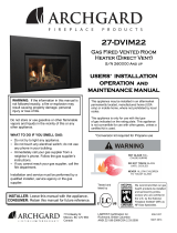
WIRING DIAGRAMS
120 VOLT CIRCUIT
THIS MOBILE/MANUFACTURED HOME APPROVED APPLIANCE MUST BE GROUNDED TO THE STEEL CHASSIS OF THE
HOME WITH A 8 GAUGE COPPER WIRE USING A SERRATED OR STAR WASHER TO PENETRATE PAINT OR PROTECTIVE
COATING TO INSURE GROUNDING.
MILLIVOLT CIRCUIT
Room Thermostat
(optional)
Remote Control (Optional)
On
Off
Pilot
Assembly
Pilot
Tube
Thermocouple
Bridge across
these terminals
(TP-TH) to test
ancillary switching
Observe good wiring practice: Label all wires prior to disconnection when servicing controls. Wiring errors can
cause damage to the unit and may cause dangerous operation. Verify proper operation after servicing.
Honeywell Valve
Blower
Thermostat
Cordset
Ground
Blower
Control
Blower
Piezo Push
Button Ignitor
TH
TH -TP
TP
TH
WARNING: Electrical Grounding Instructions
This appliance is equipped with a three-prong (grounding) plug for your protection against shock hazard and should be plugged
directly into a properly grounded three-prong receptacle. Do not cut or remove the grounding prong from this plug.

DATE PRINTED: 2/8/05 Revision Date: 04/15/04 OM-2205 Page 19
DO NOT: Use tools to operate controls, only use your hand to push in and turn the controls.
DO NOT: Try to repair the appliance. Call a qualified service technician.
DO NOT: Use this appliance if any part has been under water. Immediately call a qualified service technician to inspect
the appliance and replace any part of the gas control system which has been under water.
DO NOT: Use this appliance if you smell gas.
WHAT TO DO IF YOU SMELL GAS:
♦ OPEN WINDOWS.
♦ DO NOT TOUCH ANY ELECTRICAL SWITCH; DO NOT USE THE PHONE IN YOUR BUILDING.
♦ EXTINGUISH ANY OPEN FLAME.
♦ IMMEDIATELY CALL YOUR GAS SUPPLIER FROM A NEIGHBOR’S PHONE AND FOLLOW THE GAS SUPPLIER’S IN-
STRUCTIONS.
OPERATING INSTRUCTIONS—PRE-START UP CHECK LIST
START-UP PROCEDURE
1. Set the thermostat, if present, to the lowest level. Switch
burner switch to OFF. Set the flame adjustment knob to the
HI position. Press slightly and turn the control knob
clockwise to the OFF position and wait 5 minutes; thus
allowing any gases to escape which may have accumulated
in the combustion chamber. IF YOU SMELL GAS STOP!
FOLLOW INSTRUCTIONS ON PAGE 19.
(Note: LP gases do not vent upward). Then follow steps 2
and 3 to establish pilot.
2. Press slightly and turn control knob counterclockwise to
PILOT position; depress control knob and light pilot by
repeatedly pressing the sparker. Venting of air may take
place at the pilot prior to the flow of fuel gases. Once flame
is established, hold knob depressed for approximately 60
sec.
3. Release knob. If the pilot will not light or the control knob
does not pop up when released, turn the control knob to
OFF and call your service technician or gas supplier. If the
pilot should go out, turn the control knob to OFF position and
repeat steps 1, 2 and 3.
Note: this will allow reset of INTERLOCK for proper lighting
of pilot.
Also the Honeywell valve is equipped with a safety lockout,
once in the off position you must wait until the thermopile has
cooled down before attempting to light the pilot
(approximately 3 minutes).
4. Press and turn control knob counterclockwise to ON
position.
5. Turn flame and heat adjustment knob to the desired comfort
level from HIGH to LOW.
6. Turn thermostat to the desired comfort level or turn ON/OFF
switch to the ON position.
♦ NOTE: When first fired, the unit will produce an odor. This is
normal and is part of the paint curing process. It is
recommended that you open a few windows to ventilate the
room. This will be noticeable for at least 6 hours. During the
first hour smoke detectors in the house may be set off.
♦ Following the initial burn-in period, the glass panel may
require cleaning.
♦ CAUTION: Do not clean the glass when the appliance is
hot!
♦ When the appliance is fired from cold the glass may fog up.
This is due to condensations and is normal.
♦ Make yourself familiar with these instruction before operating
the appliance.
♦ Check any loose electrical wires that may cause a shock.
♦ Check around the appliance for gas leaks. IF YOU SMELL
GAS, follow the instructions on the front cover of this
manual.
♦ Check to see that logs are correctly positioned. The pilot
light should be visible.
♦ Check to make sure that venting is secure.
♦ Check all external parts, such as grills, doors and control
cover are properly attached and fastened.
♦ CAUTION: Do not turn the unit off and on again within a
minimum of a 60 second wait.
FOR YOUR SAFETY READ - BEFORE LIGHTING
WARNING:
WARNING: WARNING:
WARNING: IF YOU DO NOT FOLLOW THESE INSTRUCTIONS EXACTLY, A FIRE OR EXPLOSION MAY
RESULT CAUSING PROPERTY AND/OR PERSONAL INJURY
FINAL CHECK
INSTALLER: Before leaving the appliance with the customer,
you must check the operation of the appliance:
♦ Thoroughly check the entire appliance for gas leaks.
♦ Check correct rating by clocking the appliance at 15
minutes (see label).
♦ Check flame picture. Adjust primary air if required (see
page 14).
♦ Take time to go through the unit with the customer.

DATE PRINTED: 2/8/05 Revision Date: 04/15/04 OM-2205 Page 20
COMPLETE SHUT-DOWN
OPERATING INSTRUCTIONS
Press and turn the knob clockwise to the OFF position.
CONVECTION FAN OPERATION
♦ The convection fan speed control is located adjacent
to the gas controls. Turning the control knob all the
way anticlockwise will turn off the convection fan. Ad-
just the blower speed to the desired speed.
NOTE: The fan will turn on once the unit has reached
operating temperature. This prevents the discharge of cold
air.
♦ FIREBOX: You may hear some cracking or ticking
sounds on start-up and shut-down. This is due to the
expansion and contraction of the steel in the firebox.
♦ BLOWER: We use high efficiency fans in our appli-
ances. You may hear a whirring sound when the fan
turns on. This will decrease or increase depending on
the speed setting of the fan.
♦ PILOT FLAME: You may detect a very slight whisper
sound from the pilot when it is turned on.
♦ These are all normal sounds associated with this
type of appliance and should not be considered as
defects.
NORMAL OPERATING SOUNDS
To turn off the main burner only, set the thermostat to the
lowest setting or turn switch to OFF. Press and turn the
knob clockwise to PILOT position.
TEMPORARY SHUT-DOWN
CONTROL KNOB POSITIONS
Pilot On
Honeywell
Robertshaw
Burner On
Unit Off
/