Broan L100 Installation guide

Type
Installation guide
!
WARNING
TO REDUCE THE RISK OF FIRE, ELECTRIC SHOCK, OR INJURY
TO PERSONS, OBSERVE THE FOLLOWING:
1. Use this unit only in the manner intended by the manufacturer. If
you have questions, contact the manufacturer at the address or
telephone number listed in the warranty.
2. Before servicing or cleaning unit, switch power off at service panel
and lock the service disconnecting means to prevent power from
being switched on accidentally. When the service disconnecting
means cannot be locked, securely fasten a prominent warning
device, such as a tag, to the service panel.
3. Installation work and electrical wiring must be done by a qualified
person(s) in accordance with all applicable codes and standards,
including fire-rated construction codes and standards.
4. Sufficient air is needed for proper combustion and exhausting of
gases through the flue (chimney) of fuel burning equipment to pre-
vent backdrafting. Follow the heating equipment manufacturer’s
guideline and safety standards such as those published by the
National Fire Protection Association (NFPA), and the American
Society for Heating, Refrigeration and Air Conditioning Engineers
(ASHRAE), and the local code authorities.
5. When cutting or drilling into wall or ceiling, do not damage elec-
trical wiring and other hidden utilities.
6. Ducted fans must always be vented to the outdoors.
7. To reduce the risk of fire, use only metal ductwork.
8. Models L100, L150, L200, L250, and L300 only:
If this unit is to be installed over a tub or shower, it must be marked
as appropriate for the application and be connected to a GFCI
(Ground Fault Interrupter) - protected branch circuit.
9. Never place a switch where it can be reached from a tub or shower.
10. This unit must be grounded.
CAUTION
1. For general ventilating use only. Do not use to exhaust hazardous
or explosive materials and vapors.
2. To avoid motor bearing damage and noisy and/or unbalanced
impellers, keep drywall spray, construction dust, etc. off power
unit.
3. Please read specification label on product for further information
and requirements.
READ AND SAVE THESE INSTRUCTIONS
LOSONE SELECT
®
VENTILATORS
Ceiling/Wall Mount
Cooking
Equipment
Floor
COOKING AREA
Do not install above or
inside this area.
45
o
45
o
NOT FOR USE IN
A COOKING AREA.
TYPICAL INSTALLATION
MOUNTING (New Frame Construction)
Factory-shipped unit installed in new construction.
CEILING JOIST
(16” centers shown)
ROUND DUCT*
GRILLE
(Polymeric
shown)
Install after
ceiling is
finished.
MOUNTING
SCREW
GRILLE
SCREW
Blower factory-shipped
in horizontal
discharge position.
Mounting brackets
factory-shipped in
position for ½” ceil-
ing material.
ADDITIONAL
1½” FRAMING
MOUNTING (Existing Frame Construction)
Factory-shipped unit installed in existing construction.
ROUND DUCT*
GRILLE
SCREW
FINISHED
CEILING
MATERIAL
GRILLE
(Polymeric shown)
CEILING JOIST
(16” centers
shown)
2 X 4 FRAMING
(wide side down)
MOUNTING
BRACKETS
(Attached to
opposite sides
of housing & up-
side-down,
so housing is
flush with
finished ceiling)
* L100 & L150 Series uses 6” Round Duct.
L200, L250, & L300 Series uses 8” Round Duct.
1
12¼"
9
1
/
2
"
to
10
1
/
2
"
ADUSTABLE FOR VARIOUS CEILING THICKNESSES
12¼"
1½"
to
2½"
INSTALLATION FROM ABOVE FINISHED CEILING
MOUNTING OPTIONS
WIRING OPTIONS
12¼"
1
1
/
8"
MAX.
ADUSTABLE FOR VARIOUS CEILING THICKNESSES
Mounting brackets in
factory-shipped position.
(Outlet parallel to joists.)
(New construction)
12¼"
10
3
/
4"
to
11
3
/
4"
INSTALLATION FROM ABOVE FINISHED CEILING
12¼"
INSTALLATION WITH DUCTWORK
RUNNING ACROSS JOISTS
¼-20 hex nuts secure mounting brackets to housing. Loosen and
re-tighten or remove and replace nuts as necessary for desired
mounting bracket position.
Mounting brackets ipped
over and mounted to outlet
sides of housing.
(Outlet parallel to joists.)
(Existing construction)
Mounting brackets mounted
to outlet sides of housing.
(Outlet perpendicular to joists.)
(New construction)
Mounting brackets ipped
over and mounted to top of
sides of housing.
(Outlet parallel to joists.)
(New or existing construction)
12¼"
1
1
/
2"
to
2
1
/
2"
ADUSTABLE FOR VARIOUS CEILING THICKNESSES
Mounting brackets ipped
over to give approx. 1”
more clearance.
(Outlet parallel to joists.)
(New construction)
Mounting brackets mounted
to top of sides of housing.
(Outlet parallel to joists.)
(New or existing construction)
WIRING PLATE
POSITION
Wiring plate mounts to side or top of housing.
HORIZONTAL POWER
CABLE CONNECTION
VERTICAL
POWER CABLE
CONNECTION
TYPICAL INSTALLATION
WIRING
WIRING
PLATE
WHITE
TO
WHITE
BLACK
TO
BLACK
TOP / BACK
OF HOUSING
LINE IN
GROUND TO
WIRING PLATE
DUCTING (Horizontal blower discharge)
Two ways to connect ductwork to a factory-shipped unit.
Ventilator can be wired from outside of housing.
Use UL approved connectors to wire per local codes.
IMPORTANT:
Remove shipping tape from damper
Remove the shipping tape from the damper flap and make sure that
damper flap opens and closes freely inside the ductwork. Use duct
tape to make ductwork connections secure and air-tight.
Remove shipping ring from blower inlet
Remove the shipping ring from the blower inlet before operating
the ventilator.
ROOF CAP
ROUND
ELBOW*
ROUND
DUCT*
WALL
CAP
* L100 & L150 Series uses 6” Round Duct.
L200, L250, & L300 Series uses 8” Round Duct.
2
WARNING: To reduce the risk of electric shock,
disconnect from power supply before servicing.
To clean grille: Use appropriate vacuum attachment or remove
grille and clean with a soft cloth and mild soap or detergent. Dry
grille thoroughly before reinstalling.
To clean blower assembly: Remove grille, unplug blower from
housing, remove blower mounting nuts, and carefully remove blower
from housing. Use appropriate vacuum attachment or a soft cloth and
mild soap or detergent to clean blower discharge area and wheel.
DO NOT ALLOW WATER TO ENTER MOTOR. Make sure blower
assembly is completely dry before reinstalling.
Motor is permanently lubricated. Do not oil or disassemble motor.
USE AND CARE
Ventilator is designed for continuous operation. If desired, it may
be controlled using an on/off switch or a solid-state, variable speed
control. Follow wiring instructions packed with control, and adhere
to all local and state codes, and the National Electrical Code.
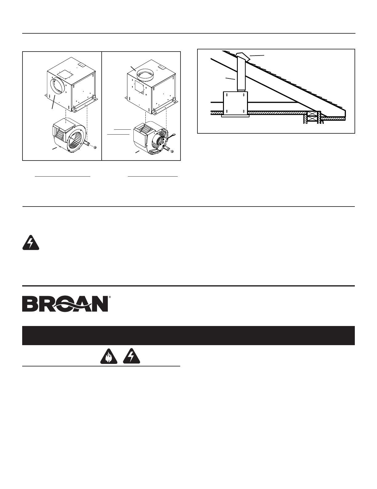
DUCTING OPTIONS
BLOWER DISCHARGE POSITIONS
Blower and duct connector
in horizontal discharge
position. (Factory shipped)
DUCT
CONNECTOR
DUCT
CONNECTOR
Blower and duct connec-
tor in vertical discharge
position.
BLOWER
BLOWER
Change
blower &
duct connec-
tor positions
for vertical
discharge.
DUCTING (Vertical blower discharge)
Typical ductwork connection to a ventilator converted to
vertical discharge.
ROOF CAP
ROUND
DUCT*
* L100 & L150 Series uses 6” Round Duct.
L200, L250, & L300 Series uses 8” Round Duct.
VENTILADORES LOSONE SELECT
®
Para montaje en cielo raso/pared
LEA Y CONSERVE ESTAS INSTRUCCIONES
ADVERTENCIA
PARA REDUCIR EL RIESGO DE INCENDIO, GOLPE ELÉCTRICO, O
LESIÓN A PERSONAS, OBSERVE LO SIGUIENTE:
1. Use esta unidad solamente de la manera indicada por el fabricante. Si
tiene preguntas, póngase en contacto con el fabricante a la dirección o
teléfono que aparecen en la garantía.
2. Antes de limpiar o de poner en servicio la unidad, apague el interruptor
en el panel de servicio, y asegure el panel de servicio para evitar que
se encienda accidentalmente. Cuando el dispositivo para desconectar el
servicio eléctrico no puede ser cerrado con algún tipo de traba, sujete
fuertemente al panel de servicio, una etiqueta de advertencia prominente.
3. El trabajo de instalación y cableado eléctrico deben estar hechos por
personal capacitado de acuerdo con todos los códigos y estándares
aplicables, incluyendo códigos y estándares de construcción a prueba
de incendios.
4. Se necesita suficiente aire para la combustión y extracción de gases por
la chimenea del equipo que quema combustible para evitar la retrogresión
de las llamas. Siga las directrices del fabricante y estándares de seguridad
como los publicados por la Asociación Nacional de Protección Contra
Incendios (o por sus siglas en inglés NFPA), y la Sociedad Americana
de Ingenieros de Calefacción, Refrigeración, y Aire Acondicionado (o por
sus sigles en inglés ASHRAE), y los códigos de las autoridades locales.
5. Cuando corte o taladre en una pared o cielo raso, no dañe cableado
eléctrico o instalaciones no visibles.
6. Ventiladores con conductos siempre deben extraer hacia el exterior.
7. Para reducir el riesgo de incendio, use sólo ductos de metal.
8. Modelos L100, L150, L200, L250, y L300 solamente:
Si esta unidad va a instalarse sobre una bañera o ducha, debe marcársela
como correcta para dicha aplicación y debe conectarse a un protegido
GFCI (Cortacicuito Accidental a Tierra).
9. Nunca instale un interruptor donde se pueda alcanzar desde una bañera
o ducha.
10. Esta unidad se debe conectar a tierra.
3
1 / 1

Broan L100 Installation guide

Type
Installation guide

Ask a question and I''ll find the answer in the document

Finding information in a document is now easier with AI

Ask the document

in other languages