Page is loading ...

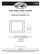
3 — Mounting hole locations) and into the surface of
the selected location.
5. Secure with the two screws provided.
6. Press front housing onto back cover.
7. Test operation. If chime does not work, see
TROUBLESHOOTING.
Temporary push button (transmitter) mounting
instructions
1. Clean the mounting location for the push button with
a mixture of 50% water and 50% isopropyl alcohol.
2. Remove protective backing from one side of the
adhesive pad and attach it to the back plate of the
push button.
3. Remove protective backing from the other side of the
adhesive pad and press the back plate to the cleaned
mounting location and hold in place for a few seconds
to allow for a secure bond.
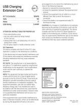
Chime (receiver) mounting instructions
NOTE: Avoid mounting on metal surfaces, as it may result in a reduced range of reception.
1. Select chime mounting location.
2. Using the chime mounting template on the package, insert card and drill two holes with
3/32" drill bit in marked keyhole slot locations (See Figure 2).
3. Insert the two included 3x25mm screws into the holes, with the screw heads extending
about ¼" from mounting surface.
4. Place the chime unit’s keyhole slots over the screws and press down on the chime unit
to secure it.
Extra chime receivers and push buttons available at www.byjasco.com.
Troubleshooting
If the chime does not work:
1. Make sure push button switch is pressed down and held for at least 1 second.
2. Verify battery installation is correct, noting polarity.
3. Try a fresh battery in push button.
4. Make sure chime is no further than 150 feet away from push button.
5. Ensure push button is not mounted on metal, near metal studs or near the floor.
6. Try a new location for the chime.
7. If the chime and push button(s) do not operate, repeat the electronic pairing process of
the push button(s) to the chime in steps A-F below:
A. To clear settings: Press and hold the pairing button on the bottom of the chime while
installing the third battery.
B. Once the last battery is installed, release the pairing
button.
C. Press and hold the pairing button again. You will
hear the “Ding Dong” melody twice, and then the
double beep to alert you the chime is ready to pair
with the push button. Release the pairing button.
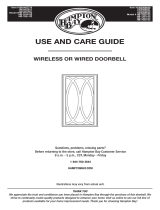
D. Press and release the push button (See Figure 4).
You will hear one beep letting you know the chime
accepted the signal.
E. Wait 10 seconds and you will hear the double beep
again to alert you the chime is now paired with the push button.
F. Press the push button to test.
Functional range may be adversely affected by one or more of the following factors:
weather, radio frequency interference, low transmitter battery and obstructions between
the transmitter and receiver.
This device complies with Part 15 of the FCC rules. Operation is subject to the following
two conditions:
(1) this device may not cause harmful interference, and (2) this device must accept any
interference received, including interference that may cause undesired operation.
FCC NOTE: The manufacturer is not responsible for any radio or TV interference caused by
unauthorized modifications to this equipment. Such modifications could void the user’s
authority to operate the equipment.
NOTE: This equipment has been tested and found to comply with the limits for a Class B
digital device, pursuant to Part 15 of the FCC Rules. These limits are designed to provide
reasonable protection against harmful interference in a residential installation. This
equipment generates, uses and can radiate radio frequency energy and, if not installed
and used in accordance with the instructions may cause harmful interference to radio
communications. However, there is no guarantee that interference will not occur in a
particular installation. If this equipment does cause harmful interference to radio or
television reception, which can be determined by turning the equipment off and on, the user
is encouraged to try to correct the interference by one or more of the following measures:
• Reorient or relocate the receiving antenna.
• Increase the separation between the equipment and receiver.
• Connect the equipment into an outlet on a circuit different from that to which the
receiver is connected.
• Consult the dealer or an experienced radio/TV technician for help.
For technical support, contact Jasco Products Company at 1-800-654-8483
or www.byjasco.com.
MADE IN CHINA
GE is a trademark of General
Electric Company and is under
license by Jasco Products
Company LLC, 10 E. Memorial Rd.,
Oklahoma City, OK 73114.
This Jasco product
comes with a 1-year
limited warranty. Visit www.byjasco.com for warranty details. Questions?
Contact us at 1-800-654-8483 between 7:00AM—8:00PM CST.
Designer
Wireless Door Chime
Installation instructions
Required Tools: Small flat blade screwdriver, #2 Phillips Screwdriver, and 1/16" and
3/32" drill bit (not included)
The wireless door chime kit has two components:
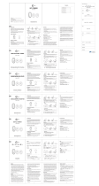
Installing battery in push button (transmitter)
1. Remove the front cover of the push button housing by pushing a flat blade screwdriver
into the slot at the bottom of the push button housing (See Figure 1).
2. Install the CR2032 battery (included) with the positive (+) side up.
3. Keep the front cover off the push button until melody selection is complete.
NOTE: The chime and push button(s) have been electronically paired during production.
Once the battery is installed in the push button and chime receiver, press the push button(s)
to ensure that the push button(s) cause the chime to operate.
IF CHIME DOES NOT SOUND, SEE TROUBLESHOOTING.
Melody Selection Setting (your chime will have either 2 or 8 melodies)
Select the melody by pushing the Melody Selection Button located inside the push button
housing (See Figure 1). Press and release the melody selection button until you hear the
desired melody. Table 1 and Table 2 shows the order the melodies will be heard.
The last melody played will be your selected chime melody.
Volume Adjustment
There are four volume settings on this chime.
1. To adjust the volume, press and release the pairing button on the chime or press the
push button to play the melody.
2. While melody is playing, press and release the volume button on the chime
to select the desired sound level.
Push button (transmitter) mounting instructions
NOTE: Avoid mounting on metal surfaces, as it may result in a reduced range of
transmission. Do not mount in an area exposed to direct rain. Push buttons are typically
mounted at the same height as the door knob or handle (between 36" and 44" above the
floor).
Permanent push button (transmitter) mounting instructions
1. Remove the front cover of the push button
(See Figure 1).
2. Before mounting, choose a mounting location that is no further than 150 feet from the
chime unit location. Place the push button where you would like to mount and test with
the chime as close to its final location as possible. If it works, continue with mounting the
button. If it does not work, see TROUBLESHOOTING.
3. Hold the back plate of the push button in the selected location with the arrow on the
back of the back plate pointing up.
4. Using the 1/16" drill bit, drill a hole through the back plate of the push button (See Figure
Chime (Receiver) Figure 2
pairingvolume
Keyhole
slots
Mounting
hole
locations
Battery
compartment
Melody
selection
button
Push
button
Figure 3
Table 2 - 8 Melody Chime
1 Dingdong
2 Westminster
3 Knocks (3 times)
4 Fanfare
5 Mozart
6 Good Vibes
7 Patriotic
8 Tango
Table 1 - 2 Melody Chime
1 Dingdong
2 Westminster
Push Button (Transmitter) Figure 1
Push
button
Mounting
hole
locations
Battery
compartment
Melody
selection
button
Push
button
Push flat blade screwdriver into
the slot to open the cover
19248
19297
19303
Version 07
6/12/2017
Push
button
Mounting
hole
locations
Battery
compartment
Melody
selection
button
Push
button
Push flat blade screwdriver into
the slot to open the cover
Figure 4

150 pies de distancia de donde se encuentra la unidad del timbre. Coloque el botón
pulsador donde desea instalarlo y pruébelo con el timbre ubicado lo más cerca posible
de su ubicación final. Si funciona, continúe con la instalación. Si no funciona, consulte
la sección RESOLUCIÓN DE PROBLEMAS.
3. Sostenga la placa posterior del botón pulsador en la ubicación seleccionada con la
flecha en la parte trasera de la placa posterior apuntando hacia arriba.
4. Con la broca de 1/16", perfore un orificio a través de la placa posterior del botón
pulsador (Ver Figura 3- Lugares de los orificios de montaje) y en la superficie del lugar
seleccionado.
5. Atornille con los dos tornillos proporcionados.
6. Pruebe si funciona. Si el timbre no funciona, consulte la sección RESOLUCIÓN DE
PROBLEMAS.
Avisador (receptor) de instrucciones de montaje
NOTA: Evite el montaje en superficies metálicas, ya que puede dar lugar a una reducción en
el alcance de la recepción.
1. Seleccione el lugar de montaje del timbre.
2. Mediante la plantilla de montaje del timbre en la tarjeta de inserción del paquete,
perfore dos agujeros con una broca de 3/32 pulg. en los lugares marcados con ranura
de ojo de cerradura. (Vea la figura 2)
3. Inserte los dos tornillos de 3 x 25 mm que se incluyen en los agujeros, dejando que las
cabezas de los tornillos sobresalgan alrededor de ¼ pulg. de la superficie de montaje.
4. Coloque las ranuras de ojo de cerradura del timbre sobre los tornillos y presione hacia
abajo la unidad de timbre para asegurarla.
Receptores de timbre adicionales y pulsadores disponibles
en www.byjasco.com.
Resolución de problemas
Si el timbre no funciona:
1. Asegúrese de que el botón pulsador esté presionado y manténgalo presionado por lo
menos durante 1 segundo.
2. Verifique la correcta instalación de la pila, teniendo en cuenta la polaridad.
3. Pruebe una pila nueva en el botón pulsador.
4. Asegúrese de que el timbre no se encuentre a una distancia mayor de 150 pies del
botón pulsador.
5. Asegúrese de que el botón pulsador no esté instalado sobre metal, cerca de montantes
de metal o cerca del piso.
6. Pruebe colocar el timbre en otro lugar.
7. Si el timbre y los botones pulsadores no funcionan, repita el proceso de vinculación
electrónica de los botones pulsadores con el timbre detallado a continuación en los
pasos del A al F.
A. Para borrar la configuración: Pulse y no suelte el botón sincronizador, ubicado en la
parte inferior del timbre, mientras enchufa el timbre al tomacorriente.
B. Tras conectar el timbre, suelte el botón sincronizador.
C. Pulse y sostenga el botón sincronizador nuevamente. Oirá dos veces la melodía “Din
Don”, y luego un doble aviso sonoro indicando que el
timbre ya se puede sincronizar con el botón pulsador.
Suelte el botón sincronizador.
D. Oprima y suelte el botón pulsador. (Vea la figura 4) Oirá
un aviso sonoro indicando que el timbre aceptó la señal.
E. Aguarde 10 segundos hasta que escuche otra vez el doble
aviso sonoro indicando que el timbre ya se sincronizó con
el botón pulsador.
F. Oprima el botón pulsador para probar que funciona.
El rango de funcionamiento podría verse afectado por uno o más de los siguientes factores:
clima, interferencia de frecuencia radial, pila baja del transmisor y bloqueos entre el
transmisor y el receptor.
Este dispositivo cumple con la Parte 15 de la normativa de la FCC. El funcionamiento está
sujeto a las siguientes dos condiciones:
(1) este dispositivo no debe provocar interferencia perjudicial, y (2) este dispositivo debe
aceptar toda interferencia que reciba, incluso la que pudiera causar un funcionamiento
no deseado.
NOTA DE LA FCC: El fabricante no se hace responsable de ninguna interferencia de radio
o TV ocasionada por modificaciones no autorizadas efectuadas a este equipo. Dichas
modificaciones podrían anular la autoridad del usuario para utilizar el equipo.
NOTA: este equipo ha sido probado y cumple con los límites para aparatos digitales de Clase B, de
conformidad con la Parte 15 de la normativa de la FCC. Estos límites están diseñados para proveer
protección razonable contra interferencias perjudiciales en una instalación residencial. Este equipo genera,
usa y puede irradiar energía de radiofrecuencias y, si no se instala y usa según las instrucciones, puede
provocar interferencia perjudicial a las radiocomunicaciones. No obstante, no hay garantías de que no
ocurrirá interferencia en una instalación en particular. Si este equipo provoca interferencia perjudicial
a la recepción de radio o televisión, lo que puede determinarse encendiendo y apagando el equipo, se
recomienda que el usuario intente corregir la interferencia por medio de la implementación de una o más
de las siguientes medidas:
• Reorientar o reubicar la antena receptora.
• Incrementar la separación entre el equipo y el receptor.
• Conectar el equipo a un tomacorriente de un circuito diferente del circuito al que está conectado el
receptor.
• Consultar al distribuidor o a un técnico con experiencia en radio/televisión para solicitar asistencia.
Para recibir asistencia técnica, comuníquese con Jasco Products Company al
1-800-654-8483 o visite www.byjasco.com
HECHO EN CHINA
GE es una marca registrada de la companía General Electric Company y
es utilizada bajo licencia a la companía Jasco Prodcucts Company LLC,
10 E. Memorial Rd., Oklahoma City, OK 73114.
Este producto de Jasco Products tiene una garantía limitada de 1 Año.
Visite www.byjasco.com para
detalles. ¿Tiene preguntas?
Comuníquese al 1-800-654-
8483 entre las 7:00 a.m. y las
8:00 p.m. CST (hora central
estándar).
Timbre inalámbrico para
puertas moderno
Instrucciones de instalación
Herramientas necesarias:
Pequeño destornillador de hoja plana y # 2 Destornillador Phillips y broca de 1/16" y
3/32“ (no incluidas)
Este kit de timbre inalámbrico para puertas posee dos componentes:
Instalación de la pila en el botón pulsador (transmisor)
1. Quite la tapa delantera de la cubierta del botón pulsador. Para ello, coloque el
destornillador de hoja plana en la ranura de la parte inferior de la cubierta. (Ver Figura 1)
2. Coloque la pila CR2032 (incluida) con la polaridad positiva(+) orientada hacia arriba.
3. Mantenga la tapa delantera separada del botón pulsador hasta que haya seleccionado
una melodía.
NOTA: el timbre y los botones pulsadores fueron vinculados electrónicamente durante la
producción. Una vez que haya colocado la pila en el botón pulsador y en el receptor del
timbre, oprima los botones pulsadores para verificar que estos activen el timbre”.
SI EL TIMBRE NO FUNCIONA, CONSULTE LA SECCIÓN RESOLUCIÓN DE PROBLEMAS.
Configuración de selección de melodía (su timbre contará con 2 o con 8 melodías)
Seleccione la melodía. Para ello oprima el Botón de selección de melodía, ubicado en
el interior de la cubierta del botón pulsador (Ver Figura 1). Oprima y suelte el botón de
selección de melodía; cuando escuche la melodía deseada, deténgase. Las Tablas 1 y 2
muestran el orden en que se reproducirán las melodías.
Quedará seleccionada la última melodía que se reprodujo.
Ajuste de volumen
Existen cuatro opciones de volumen en este timbre.
1. Para ajustar el volumen, pulse el botón sincronizador del timbre; esta acción
reproducirá la melodía.
2. Mientras la melodía se ejecuta, pulse y suelte el botón del volumen en el timbre para
seleccionar el nivel de sonido deseado.
Instrucciones para la instalación del botón pulsador
NOTA: No lo instale en superficies metálicas, ya que
puede disminuir el rango de transmisión. No lo instale en
una área que pueda verse expuesta a la lluvia directa.
Los botones pulsadores por lo general se instalan a la
misma altura de la perilla o picaporte de la puerta (a una
distancia de entre 36" y 44" del piso).
Pulsador permanente (transmisor) instrucciones
de montaje
1. Quite la tapa delantera del botón pulsador.
(Ver Figura 1)
2. Antes de instalarlo, elija un lugar que no supere los
Timbre (receptor) Figura 2
emparejamientovolumen
Ranuras ojo de
cerradura
Botón pulsador (transmisor) Figura 1
Botón
pulsador
Ubicación
de orificios
de montaje
Compartimiento
de la pila
Botón
de selección
de melodía
Botón
pulsador
Coloque un destornillador
de hoja plana en la ranura
para abrir la tapa
Tabla 2 - Timbre con 8 melodías
1 Dingdong
2 Westminster
3 Knocks (3 llamados a la puerta)
4 Fanfare (charanga)
5 Mozart
6 Good Vibes (buena vibra)
7 Patriotic
8 Tango
Tabla 1 - Timbre con 2 melodías
1 Dingdong
2 Westminster
Ubicación de
orificios de
montaje
Compartimiento
de la pila
Botón
de selección
de melodía
Botón
pulsador
Figura 3
Botón
pulsador
Ubicación
de orificios
de montaje
Compartimiento
de la pila
Botón
de selección
de melodía
Botón
pulsador
Coloque un destornillador
de hoja plana en la ranura
para abrir la tapa
Figura 4
/