
MAKING MODERN LIVING POSSIBLE
Operating Instructions
MCA 121 EtherNet/IP

Contents
1 Safety
3
1.1.2 Safety Note 3
1.1.3 Safety Regulations 3
1.1.4 Warning against Unintended Start 3
2 Introduction
4
2.1.1 About this Manual 4
2.1.2 Technical Overview 4
2.1.3 Assumptions 4
2.1.4 Hardware 4
2.1.5 Background Knowledge 4
2.1.6 Available Literature 4
2.1.7 Available literature 5
2.1.8 ODVA Conformance 5
2.1.9 Abbreviations 5
3 How to Install
6
3.1.1 The EtherNet/IP Option 6
3.1.2 How to Install Option in Frequency Converter 6
3.1.3 LED Behaviour 7
3.1.4 Topology 8
3.1.5 Network 9
3.1.6 Recommended Design Rules 10
3.1.7 EMC Precautions 11
4 How to Configure
12
4.1.1 IP Settings 12
4.1.2 Ethernet Link Parameters 12
4.1.3 Configuring the Scanner 14
4.1.4 IP traffic 16
5 How to Control
17
5.1 How to Control
17
5.1.1 I/O Assembly Instances 17
5.1.2 EtherNet/IP Connections 17
5.1.3 Class 1 connection 18
5.1.4 Class 3 connection 18
5.1.5 Unconnected Messages, UCMM 18
5.1.6 Control Word Profile 18
5.1.7 Change of State, COS 20
Contents MCA 121 EtherNet/IP
MG.90.J3.02 - VLT
®
is a registered Danfoss trademark 1

5.2 Danfoss FC Control Profile
21
5.2.1 Danfoss FC Control Profile 21
5.2.2 Status Word according to FC Profile (STW) 23
5.3 ODVA Control Profile
24
5.3.1 Control Word under Instances 20/70 and 21/71 24
5.3.2 Status Word under Instances 20/70 and 21/71 24
5.4 Reference Handling
26
5.4.1 Bus Speed Reference Value 26
5.4.2 Bus Speed Reference Value under
Instances 20/70 and 21/71 27
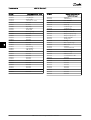
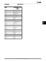
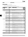
6 Parameters
28
6.1 Parameter Group 8-**
28
6.2 Parameter Group 12-**
31
6.3 Parameter List
35
6.4 Data Types
37
6.4.1 Data Types Supported by FC202/FC300 37
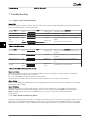
7 Troubleshooting
38
7.1.1 Step-by-step Troubleshooting 38
7.1.2 Alarm Word and Warning Word 38
8 Appendix
44
8.1.1 Supported CIP Objects 44
Index
55
Contents MCA 121 EtherNet/IP
2 MG.90.J3.02 - VLT
®
is a registered Danfoss trademark

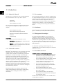
1 Safety
1.1.1 Copyright, Limitation of Liability and
Revision Rights
This publication contains information proprietary to
Danfoss. By accepting and using this manual the user
agrees that the information contained herein will be used
solely for operating equipment from Danfoss or equipment
from other vendors provided that such equipment is
intended for communication with Danfoss equipment over
an Ethernet serial communication link. This publication is
protected under the Copyright laws of Denmark and most
other countries.
Danfoss does not guarantee that a software program
produced according to the guidelines provided in this
manual will function properly in every physical, hardware
or software environment.
Although Danfoss has tested and reviewed the documen-
tation within this manual, Danfoss makes no warranty or
representation, either express or implied, with respect to
this documentation, including its quality, performance, or
fitness for a particular purpose.
In no event shall Danfoss be liable for direct, indirect,
special, incidental, or consequential damages arising out of
the use, or the inability to use information contained in
this manual, even if advised of the possibility of such
damages. In particular, Danfoss is not responsible for any
costs including but not limited to those incurred as a
result of lost profits or revenue, loss or damage of
equipment, loss of computer programs, loss of data, the
costs to substitute these, or any claims by third parties.
Danfoss reserves the right to revise this publication at any
time and to make changes in its contents without prior
notice or any obligation to notify previous users of such
revisions or changes.
1.1.2
Safety Note
WARNING
HIGH VOLTAGE
The voltage of the frequency converter is dangerous
whenever connected to mains. Incorrect installation of the
motor, frequency converter or fieldbus may cause damage
to the equipment, serious personal injury or death.
Consequently, the instructions in this manual, as well as
national and local rules and safety regulations, must be
complied with.
1.1.3 Safety Regulations
1. The frequency converter must be disconnected
from mains if repair work is to be carried out.
Check that the mains supply has been discon-
nected and that the necessary time has passed
before removing motor and mains plugs.
2. The off-command on the serial bus does not
disconnect the equipment from mains and is thus
not to be used as a safety switch.
3. Correct protective earthing or grounding of the
equipment must be established, the user must be
protected against supply voltage, and the motor
must be protected against overload in
accordance with applicable national and local
regulations.
4. The earth leakage currents are higher than
3.5mA.
5. Do not remove the plugs for the motor and
mains supply while the frequency converter is
connected to mains. Check that the mains supply
has been disconnected and that the necessary
time has passed before removing motor and
mains plugs.
1.1.4
Warning against Unintended Start
1. The motor can be brought to a stop by means of
bus commands while the frequency converter is
connected to mains. If personal safety consider-
ations make it necessary to ensure that no
unintended start occurs, these stop functions are
not sufficient.
2. While parameters are being changed, the motor
may start.
3. A motor that has been stopped may start if faults
occur in the electronics of the frequency
converter, or if a temporary overload or a fault in
the supply mains or the motor connection ceases.
WARNING
ELECTRICAL HAZARD
Touching the electrical parts may be fatal - even after the
equipment has been disconnected from mains.
Safety MCA 121 EtherNet/IP
MG.90.J3.02 - VLT
®
is a registered Danfoss trademark 3
1 1

2 Introduction
2.1.1 About this Manual
First time users can obtain the most essential information
for quick installation and set-up in these chapters:
Introduction
How to Install
How to Configure the System
For more detailed information including the full range of
set-up options and diagnosis tools please refer to the
chapters:
How to Configure the System
How to Control the frequency converter
How to Access frequency converter Parameters
Parameters
Troubleshooting
Terminology:
In this manual several terms for Ethernet is used.
- EtherNet/IP, is the term used to describe the CIP/
ODVA application protocol.
- Ethernet, is a common term used to describe the
physical layer of the network and does not relate
to the application protocol.
2.1.2
Technical Overview
EtherNet/IP
™
was introduced in 2001 and today is the most
developed, proven and complete industrial Ethernet
network solution available for manufacturing automation.
EtherNet/IP is a member of a family of networks that
implements the Common Industrial Protocol (CIP
™
) at its
upper layers. CIP encompasses a comprehensive suite of
messages and services for a variety of manufacturing
automation applications, including control, safety, synchro-
nization, motion, configuration and information. As a truly
media-independent protocol that is supported by
hundreds of vendors from around the world, CIP provides
users with unified communication architecture throughout
the manufacturing enterprise.
EtherNet/IP provides users with the network tools to
deploy standard Ethernet technology for manufacturing
applications while enabling Internet and enterprise
connectivity.
2.1.3
Assumptions
These operating instructions are under the conditions that
the Danfoss EtherNet/IP option is used in conjunction with
a Danfoss FC 200/FC 300 frequency converter, inclusive
that the installed controller supports the interfaces
described in this document and that all the requirements
stipulated in the controller, as well as the frequency
converter, are strictly observed along with all limitations
herein.
2.1.4 Hardware
This manual relates to the EtherNet/IP option MCA 121,
type no. 130B1119 (un-coated) and 130B1219 (coated).
2.1.5
Background Knowledge
The Danfoss EtherNet/IP Option Card is designed to
communicate with any system complying with the CIP
EtherNet/IP standard. Familiarity with this technology is
assumed. Issues regarding hardware or software produced
by other manufacturers, including commissioning tools, are
beyond the scope of this manual, and are not the respon-
sibility of Danfoss.
For information regarding commissioning tools, or
communication to a non-Danfoss node, please consult the
appropriate manuals.
2.1.6
Available Literature
Available Literature for the frequency converter
- The VLT AutomationDrive Operating Instructions
provide the neccessary information for getting
the frequency converter up and running.
- The VLT AutomationDrive Design Guide entails all
technical information about the frequency
converter design and applications including
encoder, resolver and relay options.
- The VLT AutomationDrive MCT 10 Operating
Instructions provide information for installation
and use of the software on a PC.
- The VLT AutomationDrive IP21 / Type 1
Instruction provides information for installing the
IP21 / Type 1 option.
- The VLT AutomationDrive 24 V DC Backup
Instruction provides information for installing the
24 V DC Backup option.
Danfoss Drives technical literature is also available online
at www.danfoss.com/drives.
Introduction MCA 121 EtherNet/IP
4 MG.90.J3.02 - VLT
®
is a registered Danfoss trademark
22

2.1.7 Available literature
Available Literature for the frequency converter
- The VLT AutomationDrive Operating Instructions
provide the neccessary information for getting
the frequency converter up and running.
- The VLT AutomationDrive Design Guide entails all
technical information about the frequency
converter design and applications including
encoder, resolver and relay options.
- The VLT AutomationDrive MCT 10 Operating
Instructions provide information for installation
and use of the software on a PC.
- The VLT AutomationDrive IP21 / Type 1
Instruction provides information for installing the
IP21 / Type 1 option.
- The VLT AutomationDrive 24 V DC Backup
Instruction provides information for installing the
24 V DC Backup option.
Danfoss Drives technical literature is also available online
at www.danfoss.com/drives.
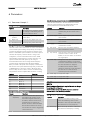
2.1.8
ODVA Conformance
The EtherNet/IP option is conformance tested to ODVA
add. industrial graded.
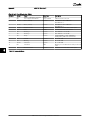
2.1.9
Abbreviations
Abbreviation Definition
API Actual Packet Interval
CC Control Card
CIP Common Industrial Protocol
CTW Control Word
DHCP Dynamic Host Configuration Protocol
EIP EtherNet/IP
EMC Electromagnetic Compatibility
I/O Input/Output
IP Internet Protocol
LCP Local Control Panel
LED Light Emitting Diode
LSB Least Significant Bit
MAR Major Recoverable fail
MAU Major Unrecoverable fail
MAV Main Actual Value (actual output)
MSB Most Significant Bit
MRV Main Reference Value
N/A Not applicable
ODVA Open DeviceNet Vendor Association
PC Personal Computer
PLC Programmable Logic Controller
PNU Parameter Number
REF Reference (= MRV)
RTC Real Time Clock
STP Spanning tree Protocol
STW Status Word
Introduction MCA 121 EtherNet/IP
MG.90.J3.02 - VLT
®
is a registered Danfoss trademark 5
2 2

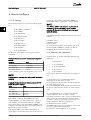
3 How to Install
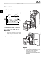
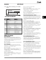
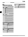
3.1.1 The EtherNet/IP Option
Ethernet Port 1
MS LED
NS LEDs
MCA 121
EtherNet/IP
MS
NS2
NS1
Ethernet Port 1 Ethernet Port 2
MAC: 00:1B:08:XX:XX:XX
Option A
130B1119
MAC
address
Ethernet Port 2
SW. ver. 1.00
130BA895.11
Illustration 3.1 Overview of the option
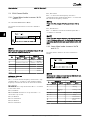
3.1.2
How to Install Option in Frequency
Converter
Items required for installing a fieldbus option in the
frequency converter:
- The fieldbus option
- Fieldbus option adaptor frame for the frequency
converter. This frame is deeper than the standard
frame, to allow space for the fieldbus option
beneath
- Strain relief (only for A1 and A2 enclosures)
EtherNet Port1
EtherNet Port2
MCA 121 Option A
EtherNet/IP 130B1119
MS
MS1 MAC-00-1B-08-00-00-22
MS2
SW.ver.
130BT797.10
Instructions:
- Remove LCP panel from the frequency converter.
- Remove the frame located beneath and discard it.
- Push the option into place. The Ethernet
connectors must be facing upwards.
- Remove both knock-outs on the fieldbus option
adaptor frame.
How to Install MCA 121 EtherNet/IP
6 MG.90.J3.02 - VLT
®
is a registered Danfoss trademark
3
3

- Push the fieldbus option adaptor frame for the
frequency converter into place.
- Replace the LCP and attach cable
NOTE
Do not strip the Ethernet cable and ground it via the strain
relief-plate! The grounding of screened Ethernet cable is
done through the RJ-45 connector on the option.
NOTE
After installing the MCA 121 option, be aware of the
following parameter settings:
8-01 Control Site: [2] Controlword only or [0] Digital and ctrl.
word
8-02 Control Word Source: [3] Option A
14-89 Option Detection: [1] Enable option Change
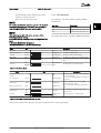
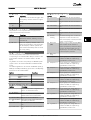
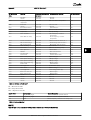
3.1.3 LED Behaviour
The option has 3 bi-coloured LEDs according to ODVA
specifications:
LED Label Description
MS Module Status
NS1 Network Status Ethernet Port 1
NS2 Network Status Ethernet Port 2
The option LEDs operate according to ODVA specifications.
State LED Description
No power Off The device is un-powered
Device operational Green: Solid green The device is operational
Standby Green: Flashing green The device needs commissioning
Minor fault Red: Flashing red The device has detected a recoverable fault
Major fault Red: Solid red The device has detected an un-recoverable
fault
Self test
Red:
Flashing red/
green
The EIP option is in self-test mode
Green:
Table 3.1 MS: Module Status
State LED Description
No IP-address (no
power)
Off
The device does not have a valid IP-address
(or is un-powered)
No connections Green: Flashing green
There are no established CIP connections to
the device
Connected Green: Solid green
There is established (at least) one CIP
connection to the device
Connection time-out Red: Flashing red
One or more CIP connections have timed-
out
Duplicate IP Red: Solid red
The IP-address assigned to the device is
already in use
Self test
Red:
Flashing red/
green
The EIP option is in self-test mode
Green
Table 3.2 NS1 + NS2: Network Status (one per port)
During normal operation the MS and at least one NS LED will show a constant green light.
How to Install MCA 121 EtherNet/IP
MG.90.J3.02 - VLT
®
is a registered Danfoss trademark 7
3
3

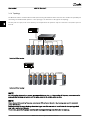
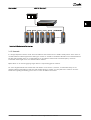
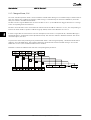
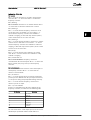
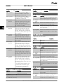
3.1.4 Topology
The MCA 121 features a build-in Ethernet-switch, thus having two Ethernet RJ-45 connectors. This enables the possibility for
connecting several EtherNet/IP options in a line topology as an alternative to the typical star-topology.
The two ports are equal, in the sense that they are transparent for the option. If only one connector is used, either port can
be used.
AutomationDrive
VLT
AutomationDrive
VLT
AutomationDrive
VLT
AutomationDrive
VLT
AutomationDrive
VLT
AutomationDrive
VLT
AutomationDrive
VLT
AutomationDrive
VLT
130BA903.10
Illustration 3.2 Star topology
AutomationDrive
VLT
AutomationDrive
VLT
AutomationDrive
VLT
AutomationDrive
VLT
AutomationDrive
VLT
AutomationDrive
VLT
AutomationDrive
VLT
130BA904.10
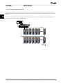
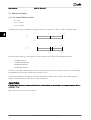
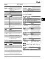
Illustration 3.3 Line topology
NOTE
For line topology please refer to section: “Recommended design rules” In a line topology all frequency converters must be
powered, either by mains or by their 24 V DC option cards, for the build-in switch to work.
NOTE
Please observe that mounting frequency converters of different power-sizes in a line topology may result in unwanted
power-off behaviour.
Smaller frequency converters discharge faster than bigger ones. This can result in loss of link in the line topology, which
may lead to control word timeout.
To avoid this, mount the frequency converters with the longest discharge time first in the line topology.
How to Install MCA 121 EtherNet/IP
8 MG.90.J3.02 - VLT
®
is a registered Danfoss trademark
3
3

AutomationDrive
VLT
AutomationDrive
VLT
AutomationDrive
VLT
AutomationDrive
VLT
AutomationDrive
VLT
½
AutomationDrive
VLT
AutomationDrive
VLT
130BA905.10
Illustration 3.4 Ring/redundant line topology
3.1.5
Network
It is of high importance that the media chosen for Ethernet data transmission are suitable. Usually CAT 5e and 6 cables are
recommended for industrial applications. Both types of cable are available as Unshielded Twisted Pair and Shielded Twisted
Pair. Generally shielded cables are recommended for use in industrial environments and with frequency converters.
A maximum cable-length of 100 m is allowed between switches.
Optical fibres can be used for gapping longer distances and providing galvanic isolation.
For connecting EtherNet/IP devices both hubs and switches can be used. It is, however, recommended always to use
suitable industrial graded Ethernet switches. Hubs should always be avoided, since they will lead to collisions. For more
information regarding IP-switching, please refer to section: IP Traffic in this manual.
How to Install MCA 121 EtherNet/IP
MG.90.J3.02 - VLT
®
is a registered Danfoss trademark 9
3
3

3.1.6 Recommended Design Rules
While designing Ethernet networks special attention and caution must be taken regarding active network components.
While designing a network for line topology it is important to notice that a small delay is added with each every switch in
the line.
It is not recommended to connect more than 32 frequency converters in a line at any API. Exceeding the recommended
design rules, may result in failing communication.
AutomationDrive
VLT
AutomationDrive
VLT
AutomationDrive
VLT
AutomationDrive
VLT
AutomationDrive
VLT
AutomationDrive
VLT
AutomationDrive
VLT
AutomationDrive
VLT
AutomationDrive
VLT
AutomationDrive
VLT
AutomationDrive
VLT
AutomationDrive
VLT
AutomationDrive
VLT
AutomationDrive
VLT
Max. 32 drives
How to Install MCA 121 EtherNet/IP
10 MG.90.J3.02 - VLT
®
is a registered Danfoss trademark
3
3

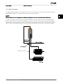
3.1.7 EMC Precautions
The following EMC precautions are recommended in order to achieve interference-free operation of the Ethernet network.
Additional EMC information is available in the frequency converter Design Guide.
NOTE
Relevant national and local regulations, for example regarding protective earth connection, must be observed.
The Ethernet communication cable must be kept away from motor and brake resistor cables to avoid coupling of high
frequency noise from one cable to the other. Normally a distance of 200 mm (8 inches) is sufficient, but maintaining the
greatest possible distance between the cables is recommended, especially where cables run in parallel over long distances.
When crossing is unavoidable, the Ethernet cable must cross motor and brake resistor cables at an angle of 90 degrees.
A utomation Driv e
VLT
.
Motor cable
Brake resistor cable
1
How to Install MCA 121 EtherNet/IP
MG.90.J3.02 - VLT
®
is a registered Danfoss trademark 11
3
3

4 How to Configure
4.1.1 IP Settings
All IP-related parameters are located in parameter group
12-0*:
-
12-00 IP Address Assignment
-
12-01 IP Address
-
12-02 Subnet Mask
-
12-03 Default Gateway
-
12-04 DHCP Server
-
12-05 Lease Expires
-
12-06 Name Servers
-
12-07 Domain Name
-
12-08 Host Name
-
12-09 Physical Address
The MCA 121 option offers several ways of IP address
assignment.
Setting up frequency converter with manual assigned IP
address:
Parameter
Value
12-00 IP Address Assignment
[0] MANUAL
12-01 IP Address
192.168.0.xxx*
12-02 Subnet Mask
255.255.255.0*
12-03 Default Gateway
optional
*= Class C IP address example. Any valid IP address can be entered.
NOTE
A power-cycle is necessary after setting the IP parameters
manually.
Setting up frequency converter with automatic (BOOTP/
DHCP) assigned IP address:
Name
Value
12-00 IP Address
Assignment
[0] Manual/[1] DHCP/[2] BOOTP
12-01 IP Address
Read only
12-02 Subnet Mask
Read only
12-03 Default Gateway
Read only
By IP address assigned by DHCP/BOOTP server, the
assigned IP Address and Subnet Mask can be read out in
12-01 IP Address and 12-02 Subnet Mask. In 12-04 DHCP
Server, the IP address of the found DHCP or BOOTP server
is displayed. For DHCP only: The remaining lease-time can
be read-out in 12-05 Lease Expires.
12-09 Physical Address reads out the MAC address of
option, which is also printed on the label of the option. If
using fixed leases together with DHCP or BOOTP, the
physical MAC address is linked with a fixed IP address.
NOTE
If no DHCP or BOOTP reply has been received after 4
attempts (e.g. if the DHCP/BOOTP server has been
powered off), the option will fallback to the last good
known IP address.
12-03 Default Gateway is optional and only used in routed
networks.
12-06 Name Servers
12-06 Name Servers
12-08 Host Name
Are used with Domain Name Server systems and are all
optional. If DHCP or BOOTP is selected as IP address
assignment, these parameters are read only.
4.1.2
Ethernet Link Parameters
Parameter group 12-1* holds information Ethernet Link
information:
-
12-10 Link Status
-
12-11 Link Duration
-
12-12 Auto Negotiation
-
12-13 Link Speed
-
12-14 Link Duplex
Please note the Ethernet Link Parameters are unique per
port.
12-10 Link Status and 12-11 Link Duration displays
information on the link status, per port.
12-10 Link Status will display Link or No Link according to
the status of the present port.
12-11 Link Duration will display the duration of the link on
the present port. If the link is broken the counter will be
reset.
12-12 Auto Negotiation – is a feature that enables two
connected Ethernet devices to choose common
transmission parameters, such as speed and duplex mode.
In this process, the connected devices first share their
capabilities as for these parameters and then choose the
fastest transmission mode they both support.
By default this function is enabled.
Incapability between the connected devices, may lead to
decreased communication performance.
To prevent this, Auto Negotiation can be disabled.
How to Configure MCA 121 EtherNet/IP
12 MG.90.J3.02 - VLT
®
is a registered Danfoss trademark
44

If 12-12 Auto Negotiation is set to OFF, link speed and
duplex mode can be configured manually in 12-13 Link
Speed and 12-14 Link Duplex.
12-13 Link Speed – displays/sets the link speed per port.
“None” is displayed if no link is present.
12-14 Link Duplex – displays/sets the duplex mode per
port.
Half-duplex provides communication in both directions,
but only in one direction at a time (not simultaneously).
Full-duplex allows communication in both directions, and
unlike half-duplex, allows for this to happen simulta-
neously.
How to Configure MCA 121 EtherNet/IP
MG.90.J3.02 - VLT
®
is a registered Danfoss trademark 13
4 4

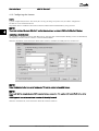
4.1.3 Configuring the Scanner
EDS file
a generic English EDS (Electronic Data Sheet) file covering all voltage and power sizes, for off-line configuration.
The EDS file can be downloaded from:
http://www.danfoss.com/BusinessAreas/DrivesSolutions/Softwaredownload/DDFieldbus_Setup_Files.htm
NOTE
The current version of the major EtherNet/IP configuration tools does not support EDS-files for EtherNet/IP devices.
Configuring a Rockwell Master
For configuring a frequency converter with MCA 121 for operation with a Rockwell (Allen-Bradley) Scanner via EtherNet/IP,
the frequency converter must be added as a Generic Ethernet Module.
Under the General-tab, enter information about: Name of device, IP Address, Assembly Instance and Data size
130BA909.11
NOTE
Under Configuration in the Connection Parameters a “4” must be entered as Assembly Instance.
NOTE
Please note that the example shows a 20/70 assembly instance connection. This requires 8-10 Control Profile to be set to:
ODVA.
Other supported connections are shown in section: I/O Assembly Instanced.
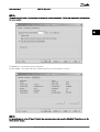
Under the Connection-tab, enter information about: RII and fault conditions.
How to Configure MCA 121 EtherNet/IP
14 MG.90.J3.02 - VLT
®
is a registered Danfoss trademark
44

NOTE
The used of point to point is recommended to increase the network performance. If listen only connection is used, multicast
has to be selected.
130BA910.11
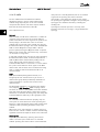
The Module Info – This tap holds generic information.
The Reset Module – This button will make a simulated Power-cycle of the frequency converter.
130BA911.11
NOTE
For more information on the CIP class 1 Forward Open command, please refer to section: EtherNet/IP Connections under the
How to Control -chapter.
How to Configure MCA 121 EtherNet/IP
MG.90.J3.02 - VLT
®
is a registered Danfoss trademark 15
4 4

4.1.4 IP traffic
The use of Ethernet based network for industrial
automation purposes, calls for careful and thorough
network design. Especially the use of active network
components like switches and routers requires detailed
know-how about the behaviour of IP traffic.
Some important issues:
Multicast
Multicast traffic; is traffic that is addressed to a number of
recipients. Each host processes the received multicast
packet to determine if it is the target for the packet. If not,
the IP package is discarded. This causes an excessive
network load of each node in the network since they are
flooded with multicast packages. The nature of EtherNet/IP
traffic is that all Originator-to-Target traffic is Unicast
(point-to-point) but Target-to-Originator traffic is optional
Multicast. This enables that several listen only -connections
can be made to a single host.
In switched networks hosts also have the risk of becoming
flooded with multicast traffic. A switch usually forwards
traffic by MAC address tables build by looking into the
source address field of all the frames it receives.
A multicast MAC address is never used as a source address
for a packet. Such addresses do not appear in the MAC
address table, and the switch has no method for learning
them, so it will just forward all multicast traffic to all
connected hosts.
IGMP
IGMP (Internet Group Management Protocol) is an
integrated part of IP. It allows hosts to join or leave a
multicast host group. Group membership information is
exchanged between a specific host and the nearest
multicast router.
For EtherNet/IP networks it is essential that the switches
used, supports IGMP Snooping. IGMP Snooping enables
the switch to “listen in" on the IGMP conversation between
hosts and routers. By doing this the switch will recognise
which hosts are members of which groups, thus being able
to forward multicast traffic only to the appropriate hosts.
Redundancy
For an Ethernet network to function properly, only one
active path can exist between two nodes. Spanning-Tree
Protocol is a link management protocol that provides path
redundancy while preventing undesirable loops in the
network.
When loops occur, some switches see stations appear on
both sides of it self. This condition confuses the forwarding
algorithm and allows for duplicate frames to be forwarded.
Spanning tree
To provide path redundancy, Spanning-Tree Protocol
defines a tree that spans all switches in an extended
network. Spanning-Tree Protocol forces certain redundant
data paths into a standby (blocked) state. If one network
segment in the Spanning-Tree Protocol becomes
unreachable, or if Spanning-Tree Protocol costs change,
the spanning-tree algorithm reconfigures the spanning-tree
topology and re-establishes the link by activating the
standby path.
Spanning-Tree Protocol operation is necessary if the
frequency converters are running in a ring/redundant line
topology.
How to Configure MCA 121 EtherNet/IP
16 MG.90.J3.02 - VLT
®
is a registered Danfoss trademark
44

5 How to Control
5.1 How to Control
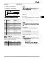
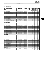
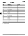
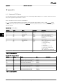
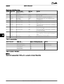
5.1.1 I/O Assembly Instances
I/O Assembly Instances are a number of defined process control objects with defined content comprising control and status
information.
Unlike DeviceNet it is possible to run with asymmetrical instances. E.g. 101/153 = 8 bytes/20 bytes.
It is not possible to mix instances across profiles, e.g. 20/100. Assembly instances must be consistent to the: ODVA or FC
profile.
The controlling instance can be read in par. 12-20, Control Instance.
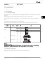
The figure below shows the I/O Assembly Instance options for controlling and monitoring the frequency converter.
Profile
(8-10 Control Word
Profile)
Direction
Instances
(decimal)
Size
(bytes)
Data
ODVA
Originator →Target
20 4
21 4
Target →Originator
70 4
71 4
FC
Originator →Target
100 4
101 8
103 20
Target →Originator
150 4
151 8
153 20
NOTE
Use of 32-bit process data.
For configuration of a 2-word (32-bit) parameter read/write, use 2 consecutive arrays in par. 12-21 and 12-22, like [2]+[3],
[4]+[5], [6]+[7] etc. Read/write of 2-word values in arrays like: [3]+[4], [5]+[6], [7]+[8] are not possible.
5.1.2 EtherNet/IP Connections
The MCA 121 option supports the CIP connections described in the following sections:
How to Control MCA 121 EtherNet/IP
MG.90.J3.02 - VLT
®
is a registered Danfoss trademark 17
5 5

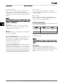
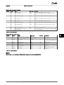
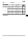
5.1.3 Class 1 connection
I/O connection using TCP transport. Maximum one Class 1
connection is supported by the EtherNet/IP option, but
several listen only connection can be established if
multicast is selected as Transport type. This type of
connection is used for cyclic I/O and Change-Of-State
connections. The connection is established with a Forward
Open command, containing the following information:
Transport Type:
Specified for both directions:
- Originator-to-Target / Target-to-Originator.
- Point to Point
- Multicast (Target-to-Originator only)
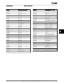
Data Size:
Specified (in bytes) for both directions: Originator ->
Target / Target -> Originator.
The data-size depends on the assembly-instance chosen in:
Destination.
Instances (decimal) Data Size
Originator →Target Target →Originator
20, 21, 100 70, 71, 150 4 bytes
101 151 8 bytes
103 153 20 bytes
Packet Rate:
Specified (in milliseconds) for both directions: Originator ->
Target / Target -> Originator.
Minimum packet rate supported: 1 ms
Production Inhibit Timeout:
Specifies (in milliseconds) the timeout-time for both
directions.
Trigger:
Selects the transport trigger type:
- Cyclic (Data is transmitted based on API)
- Change Of State (Data is transmitted on Change
of State only. COS-filters are set-up in par. 12-38
COS Filters)
Connection Points
Specified for both directions: Originator -> Target / Target -
> Originator.
Profile
(8-10 Control Word
Profile)
Direction Connection Points
(decimal)
ODVA
Originator →Target
20, 21
Target →Originator
70, 71
FC
Originator →Target
100, 101, 103
Target →Originator
150, 151, 153
5.1.4 Class 3 connection
Cyclic connection using UDP transport.
Maximum 6 Class 3 connections are supported.
This type of connection is used for explicit messaging. The
connection is established with a Forward Open command,
containing the following information:
Connection Name:
Given name for the connection
Message Parameters
- Service Code
- Class
- Instance
- Attribute
- Member
- Request Data
5.1.5
Unconnected Messages, UCMM
Non-cyclic (single) connection using TCP transport.
This type of connection is used for explicit messaging. The
connection is established on-the-fly and does not require
any Forward Open command.
Message Parameters
- Service Code
- Class
- Instance
- Attribute
- Member
- Request Data
Please refer to section Appendix for information on
accessing CIP objects explicitly.
5.1.6
Control Word Profile
The Control profile is selected in 8-10 Control Word Profile
- ODVA; gives access to the ODVA specific profiles
and assembly instances: 20, 21, 70 and 71
- FC; enables the Danfoss profile and assembly
instances: 100, 101, 103, 150, 151 and 153
For more information on the different profiles, please refer
to the subsequent sections.
How to Control MCA 121 EtherNet/IP
18 MG.90.J3.02 - VLT
®
is a registered Danfoss trademark
55

NOTE
Change of control profile
It is only possible to change the Control profile while the
frequency converter is stopped. Control word and
reference will not be recalculated to match the selected
profile, but are kept at the last good known value.
How to Control MCA 121 EtherNet/IP
MG.90.J3.02 - VLT
®
is a registered Danfoss trademark 19
5 5
Page is loading ...
Page is loading ...
Page is loading ...
Page is loading ...
Page is loading ...
Page is loading ...
Page is loading ...
Page is loading ...
Page is loading ...
Page is loading ...
Page is loading ...
Page is loading ...
Page is loading ...
Page is loading ...
Page is loading ...
Page is loading ...
Page is loading ...
Page is loading ...
Page is loading ...
Page is loading ...
Page is loading ...
Page is loading ...
Page is loading ...
Page is loading ...
Page is loading ...
Page is loading ...
Page is loading ...
Page is loading ...
Page is loading ...
Page is loading ...
Page is loading ...
Page is loading ...
Page is loading ...
Page is loading ...
Page is loading ...
Page is loading ...
Page is loading ...
Page is loading ...
Page is loading ...
-
 1
1
-
 2
2
-
 3
3
-
 4
4
-
 5
5
-
 6
6
-
 7
7
-
 8
8
-
 9
9
-
 10
10
-
 11
11
-
 12
12
-
 13
13
-
 14
14
-
 15
15
-
 16
16
-
 17
17
-
 18
18
-
 19
19
-
 20
20
-
 21
21
-
 22
22
-
 23
23
-
 24
24
-
 25
25
-
 26
26
-
 27
27
-
 28
28
-
 29
29
-
 30
30
-
 31
31
-
 32
32
-
 33
33
-
 34
34
-
 35
35
-
 36
36
-
 37
37
-
 38
38
-
 39
39
-
 40
40
-
 41
41
-
 42
42
-
 43
43
-
 44
44
-
 45
45
-
 46
46
-
 47
47
-
 48
48
-
 49
49
-
 50
50
-
 51
51
-
 52
52
-
 53
53
-
 54
54
-
 55
55
-
 56
56
-
 57
57
-
 58
58
-
 59
59


Danfoss VLT AQUA Drive FC 202 Installation guide
- Type
- Installation guide
- This manual is also suitable for
Ask a question and I''ll find the answer in the document
Finding information in a document is now easier with AI
Related papers
-
Danfoss VLT Midi Drive FC 280 User guide
-
Danfoss VLT AutomationDrive FC 301 Installation guide
-
Danfoss VLT BACnet/IP MCA 125 Installation guide
-
-
-
Danfoss VLT AutomationDrive FC 302 Installation guide
-
Danfoss VLT® AutomationDrive FC302, 315-710 kW,E User guide
-
Danfoss VLT® AutomationDrive User guide
-
-
Other documents
-
Datalogic EtherNet/IP DS6 00 Series Installation and User Manual
-
red lion 7000 Series Installation and User Manual
-
Baumer GBAMS Owner's manual
-
Baumer PMG10 - EtherNet/IP Owner's manual
-
Bernard Controls Fielbus Solution PRIOFIBUS DP FOR INTELLI+ Installation & Operation Manual
-
 Rockwell Automation Allen-Bradley Bulletin 1609 Quick start guide
-
Mitsubishi Electric MITSUBISHI CNC EtherNet/IP User manual
-
Ascon tecnologic EP4 User manual
-
WEG MVW-01 User guide
-
turck TBEN-LF Operating instructions
