Page is loading ...

1
WARNING: To ensure the drive is not unexpectedly
started, turn off and lock-out or tag power source before
proceeding. Failure to observe these precautions could
result in bodily injury.
WARNING: All products over 25 kg (55 lbs) are noted on the
shipping package. Proper lifting practices are required for
these products.
Dodge
®
TAF Pillow Blocks & S-1 Units
These instructions must be read thoroughly before installation or operation. This instruction manual was accurate at the time of printing. Please see
baldor.com for updated instruction manuals.
Note! The manufacturer of these products, Baldor Electric Company, became ABB Motors and Mechanical Inc. on
March 1, 2018. Nameplates, Declaration of Conformity and other collateral material may contain the company name of Baldor Electric
Company and the brand names of Baldor-Dodge and Baldor-Reliance until such time as all materials have been updated to reflect our
new corporate identity.
WARNING: Because of the possible danger to person(s) or
property from accidents which may result from the improper
use of products, it is important that correct procedures be
followed. Products must be used in accordance with the
engineering information specified in the catalog. Proper
installation, maintenance and operation procedures must
be observed. The instructions in the instruction manuals
must be followed. Inspections should be made as necessary
to assure safe operation under prevailing conditions. Proper
guards and other suitable safety devices or procedures as
may be desirable or as may be specified in safety codes
should be provided, and are neither provided by ABB nor
are the responsibility of ABB. This unit and its associated
equipment must be installed, adjusted and maintained by
qualified personnel who are familiar with the construction
and operation of all equipment in the system and the
potential hazards involved. When risk to persons or property
may be involved, a holding device must be an integral part
of the driven equipment beyond the speed reducer output
shaft.
Fitting or Replacing a Unit in a Pillow Block
1. Up to 5” bore, match marks have been stamped on the mating
faces of the cap and base of each outer housing. Over 5” bore
match mark cap and base of each outer housing before removing
cap. When reassembling pillow block make sure match marks
on cap and base match. At this time do not remove shims found
between the cap and base.
2. Lubricate bearing seat on the cap and on the base of the outer
housing with an anti-seize compound.
3. Fit each unit to its outer housing before carrying out Step 7. Place
the unit in the pillow block base and install cap. Tighten cap bolts
to specied torque in Table 1.
4. Add or remove shims between cap and base as required to obtain
“snug” t of unit in outer housing with cap bolts tightened to
specied torque in Table 1.
5. Check t by prying against lubrication stud in unit through the
lubrication hole in housing cap with a screwdriver or small pinch
bar depending upon the size of the pillow blocks.
6. The effort required to turn the shaft should be the same before and
after bolting bearings to the support.
7. The “snug” t becomes a matter of judgment. A “loose or sloppy”
t may allow a unit mount to move in its outer housing thus wearing
the mating surfaces. Too “tight” a t will not allow the unit to move
and compensate for misalignment and for shaft deection caused
by belt pull and dead weight.
8. Install bearings per installation instructions contained in this
manual.
Table 1 - Cap Bolt Torque
Bore Size (In.)
2 Bolt Base 4 Bolt Base
Bolt Size
Torque
Ft.-Lbs.
Bolt Size
Torque
Ft.-Lbs.
1-7/16 thru 1-11/16 3/8 –16 24–30 – –
1-15/16 thru 2-3/16 7/16 –14 40–50 – –
2-7/16 thru 2-1/2 1/2–13 60–75 1/2–13 60–75
2-11/16 thru 3 5/8–11 120 –15 0 5/8–11 120 –15 0
3-7/16 thru 3-1/2 3/4–10 208–260 3/4 –10 208–260
3-15/16 thru 4 – – 3/4–10 208–260
4-7/16 thru 4-1/2 – – 7/8 –9 344–430
4-15/16 thru 5 – – 1–8 512– 640
5-7/16 thru 6 – – 1–8 512– 640
6-7/16 thru 7 – – 1–8 512– 640
INSTALLATION
1. Shaft must be clean, free of burrs and lubricated. File nicks from
housing bases.
2. Loosen setscrews in collar and slide bearings on shaft. If force
is necessary, tap inner race only with a light drift. For vertical
applications, locate adjusting nut on bearing so nut faces upward.
3. Position expansion (oating) pillow block on mounting surface.
Tighten base hold-down bolts. (Use Grade 8 bolts for heavy loads.)
4. Position non-expansion (xed) pillow block in correct relation to shaft
and mounting surface. Tighten base holddown bolts.(Use Grade 8
bolts for heavy loads.) Then torque setscrews in collar per Table 2.
Table 2 - Set Screw Torque
Bore Size (in.) Set Screw Size In.-Lbs.
1-3/16 thru 1-11/16 5/16 165
1-3/4 thru 2-1/2 3/8 290
2-11/16 thr u 3-1/ 2 1/2 620
3-15/16 thru 5 5/8 1325
5-7/16 thru 6 3/4 2150
6-7/16 thru 7 7/8 5130
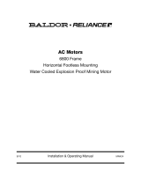
5. Mount a dial indicator on the shaft near the non-expansion (xed)
bearing. Place the indicator probe so that it contacts the machined
surface of the S-1 Unit Housing perpendicular to that surface. See
Figure 1. Note that only one face of the S-1 Unit is a machined face.
6. Zero the indicator and sweep the machined face 360°, noting the
total indicator turnout (TIR).
7. If the TIR is less than or equal to the value shown on Table 3, tighten
the housing cap bolts per Table 1.
8. If the TIR is greater than shown on Table 3, gently tap the machined
face of the S-1 housing until the TIR is less than or equal to the
value shown on Table 3. Then torque the housing cap bolts per
Table 1. Sweep machined faces again to verify that the TIR is still
less than or equal to the value shown on Table 3.
9. The non-expansion (xed) bearing is now installed. Move to the
expansion (oating) bearing.
10. Locate expansion unit in center of its axial travel or at extreme
if maximum expansion is required (do not preload stop pin) and
torque collar setscrews per Table 2.
11. Do not install external grease ttings until completion of nal steps
below.
12. Torque setscrews of expansion unit (Table 2).
13. Repeat Steps 6, 7, 8 and 9 for the expansion bearing.
14. The expansion (oating) bearing is now installed.

—
ABB Motors and Mechanical Inc.
5711 R. S. Boreham Jr. Street
Fort Smith, AR 72901
Ph: 1.479.646.4711
Mechanical Power Transmission Support
Ph: 1.864.297.4800
new.abb.com/mechanical-power-transmission
baldor.com
© ABB Motors and Mechanical Inc.
MN3040 (Replaces 499615)
*3040-0718*
All Rights Reserved. Printed in USA.
07/18 Litho 20,000
EXP
NON-EXP
SHAFT
CAST SURFACE
MACHINED SURFACE
PROBE
DIAL INDICATOR
STRAP OR
MAGNETIC
BASE
Figure 1 - Mounting Diagram
Table 3 - Total Indicator Run-out (TIR)
Shaft Size (Inches) TIR (Inches)
1-7/16 0.0030
1-11/16 0.0035
1-15/16 0.0040
2-3/16 0.0040
2-7/16 thru 2-1/2 0.0045
2-11/16 thru 3 0.0055
3-7/16 thru 3-1/2 0.0065
3-15/16 thru 4 0.0070
4-7/16 thru 4-1/2 0.0080
4-15/16 thru 5 0.0085
5-17/16 thru 6 0.015
6-7/16 thru 7 0.020
LUBRICATION GUIDELINES
This bearing is factory lubricated with a lithium or lithium complex
base grease which is suitable for most applications. However, extra
protection is necessary if the bearing is subjected to excessive
moisture, dust, corrosive vapor or other harsh environments. In these
cases, the bearing should contain as much grease as speed will permit
(a full bearing with consequent slight leakage through the seal is the
best protection against contaminant entry).
For relubrication, select a grease that is compatible with a lithium
or lithium complex grease. The following table is a general guide for
normal operating conditions. However, some situations may require a
change in lubricating periods as dictated by experience.
Normal Operation — This bearing has been greased at the factory
and is ready to run. The following table is a general guide for re-
lubrication. However, certain conditions may require a change of
lubricating periods as dictated by experience. See “High Speed
Operation” and “Operation in Presence of Dust, Water or Corrosive
Vapors” above.
High Speed Operation — High speed operation is 70% of maximum
catalog speed and above. In the higher speed ranges too much grease
will cause overheating. The amount of grease that the bearing will
take for a particular high speed application can only be determined by
experience — see “Operating Temperature” below. If excess grease
in the bearing causes overheating, it will be necessary to remove
grease tting (also drain plug when furnished) to permit excess grease
to escape. The bearing has been greased at the factory and is ready
to run. When establishing a re-lubrication schedule, note that a small
amount of grease at frequent intervals is preferable to a large amount
at infrequent intervals.
Operation in Presence of Dust, Water or Corrosive Vapors —
Under these conditions the bearing should contain as much grease as
speed will permit, since a full bearing with consequent slight leakage
is the best protection against entrance of foreign material. In the higher
speed ranges too much grease will cause overheating— see “High
Speed Operation” above. In the lower speed ranges it is advisable
to add extra grease to a new bearing before putting into operation.
Bearings should be greased as often as necessary (daily if required) to
maintain a slight leakage at the seals.
Operating Temperature — Abnormal bearing temperature may
indicate faulty lubrication. Normal temperature may range from a few
degrees up to 100ºF above ambient, depending on bearing size, speed,
loading and environmental conditions. Unusually high temperature, in
this range, accompanied by excessive leakage of grease indicates too
much grease. In the circumstances that there is excess grease in the
bearing, remove the grease tting to allow the excess grease to purge.
When purging ceases, wipe excess grease with a clean rag and screw
tting back into the bearing. High temperature with no grease showing
at the seals particularly if the bearing seems noisy, usually indicates too
little grease. Normal temperature and a slight showing of grease at the
seals indicate proper lubrication.
Lubrication Guide
Read preceding paragraphs before establishing lubrication schedule.
Table 4 - Suggested Lubrication Period In Weeks
Hours Run
Per day
1-250
RPM
251-500
RPM
501-750
RPM
751-1000
RPM
1001-1500
RPM
8 12 12 10 7 5
16 12 7 5 4 2
24 10 5 3 2 1
Lubrication recommendations are intended for standard products
applied in general operating conditions. For modied products, high
temperature environments and other anomalous applications, contact
product engineering at 864.284.5700.
Kind of Grease — Many ordinary cup greases will disintegrate
at speeds far below those at which DODGE bearings will operate
successfully if proper grease is used. DODGE bearings have been
lubricated at the factory with an NLGI #2 lithium complex base grease.
DODGE bearings greater than 5” shaft size have been lubricated with
an NLGI #2 EP additive lithium base grease. Re-lubricate with lithium-
base or lithium complex-base grease, or a grease which is compatible
with original lubricant and suitable for roller bearing service. In
unusual or doubtful cases the recommendation of a reputable grease
manufacturer should be secured.
Storage or Special Shutdown — If exposed to wet or dusty
conditions or to corrosive vapors, extra protection is necessary. Add
grease until it shows at the seals; rotate the bearing to distribute
grease; cover the bearing. After storage or idle period, add a little fresh
grease before running. During long idle periods, rotate shaft at least
once a month.
Special Operating Conditions — Refer acid, chemical, extreme or
other special operating conditions to your local representative.
/