
Bosch Installation Manual:
NGT/NGP

Safety . . . . . . . . . . . . . . . . . . . . . . . . . . . . . . . . . . . . . . . . . . . . . . . . . . . . . 1
Important Safety Instructiond. . . . . . . . . . . . . . . . . . . . . . . . . . . . . . . . . . . . . . . . . . . . . . . . . . . . . 3
Installation . . . . . . . . . . . . . . . . . . . . . . . . . . . . . . . . . . . . . . . . . . . . . . . . . . 3
Before You Begin . . . . . . . . . . . . . . . . . . . . . . . . . . . . . . . . . . . . . . . . . . . . . . . . . . . . . . . . . . . . . 3
Installation Procedure . . . . . . . . . . . . . . . . . . . . . . . . . . . . . . . . . . . . . . . . . . . . . . . . . . . . . . . . . . 6
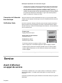
Service . . . . . . . . . . . . . . . . . . . . . . . . . . . . . . . . . . . . . . . . . . . . . . . . . . . . 8
Before Calling Service . . . . . . . . . . . . . . . . . . . . . . . . . . . . . . . . . . . . . . . . . . . . . . . . . . . . . . . . . . 8
Table of Contents
Questions?
1-800-944-2904
www.boschappliances.com
5551 McFadden Ave.
Huntington Beach, CA 92649
We look forward to hearing from you!

English 1
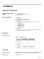
IMPORTANT SAFETY INSTRUCTIONS
READ AND SAVE THESE INSTRUCTIONS
INSTALLER: LEAVE THESE INSTRUCTIONS WITH THE APPLIANCE AFTER INSTALLATION IS COMPLETE.
IMPORTANT: SAVE FOR THE LOCAL INSPECTOR'S USE.
Important Safety
Instructions
WARNING: Improper installation, adjustment, alteration, service or
maintenance can cause injury or property damage. Refer to this man-
ual. For assistance or additional information consult a qualified
installer, service agency, manufacturer or the gas supplier.
• Have the installer show you the location of the circuit breaker or fuse. Mark it
for easy reference.
• Be sure your appliance is properly installed and grounded by a qualified tech-
nician.
Safety Codes and Specifications • Installation must conform with local codes or, in the absence of local codes
with the National Fuel Gas Code, ANSI Z223.1.
• The appliance must be electrically grounded in accordance with local codes
or, in the absence of local codes, with the National Electrical Code ANSI/
NFPA 70, latest edition. (In Canada, installation must be in accordance with
the CAN 1-B149.1 and .2 Installation Codes for Gas Burning Appliances and/
or local codes.)
• This appliance has been tested in accordance with ANS Z21.1, Standard for
Household Cooking Appliances (USA) and in accordance with CANl.l-M81
Interim Reqt #58 Domestic Gas Cooktops (CANADA).
• Additional requirements and standards may apply in specific installations.
Equipment and Usage Safety
Requirements
• The cooktop must be used in conjunction with a suitable ventilation system.
• Before plugging in an electrical cord, be sure all controls are in OFF position.
Power Requirements and Electrical
Grounding Instructions
• Power Supply: 120 Volts, 15 Ampere, 60 Hz. This appliance is factory
equipped with a 5-foot power supply cord with a 3-prong grounding plug (with
polarized parallel blades).
• To prevent electrical shock, the third ground prong should not under any cir-
cumstances, be cut or removed. It must be plugged into a matching grounding
type receptacle, connected to a correctly polarized 120-volt circuit.
• A separate circuit is recommended which is in compliance with the NEC. If
there is any doubt as to whether the wall receptacle is properly grounded, the
customer should have it checked by a qualified electrician.
Gas Requirements • A manual valve must be installed in an accessible location in the gas line
external to the appliance for the purpose of turning on and shutting off the gas
to the appliance.
• Leak testing of the appliance shall be conducted according to manufacturer’s
instructions.
Safety

English 2
Gas Supply Pressure • Natural Gas - 6 inches water column (14.9 Millibars) minimum.
• Propane Gas -11 inches water column (27.4 Millibars) minimum.
The maximum supply pressure to this appliance shall not exceed 14.0 inches
water column (34.9Millibars).
Gas Appliance Safety
Propane Gas Installation (NGT Mod-
els only)
NOTE: NGP models cannot be converted for propane use.
The propane gas tank must be equipped with its own high pressure regulator in
addition to the pressure regulator supplied with this unit. The cooktop is shipped
from the factory for use with natural gas. For use with LP, a conversion kit is
required and must be purchased separately. Contact BSH or your retailer to
obtain kit # NEZ10
56. A qualified technicia
n or installer must do the conversion.
High Alti
tude Installation This cooktop has been CSA certified for safe operation up to a height of 10,000 ft.
(3,048 m) without any modifications to components for natural gas or after LP
conversion.
For Massachusetts Installations • Installation must be performed by a qualified or licensed contractor, plumber
or gas fitter qualified or licensed by the state, province or region where this
appliance is being installed.
• Shut-off valve must be a “T” handle gas cock.
• Flexible gas connector must not be longer than 36 inches (91cm).
WARNING: If the information in this manual is not
followed exactly, a fire or explosion may result caus-
ing property damage, personal injury or death.
Do not store or use combustible materials, gasoline or other flam-
mable vapors and liquids in the vicinity of this or any other appli-
ance.
• WHAT TO DO IF YOU SMELL GAS:
•Do not try to light any appliance.
•Do not touch any electrical switch.
•Do not use any phone in your building.
•Immediately call your gas supplier from a neighbor’s phone.
Follow the gas supplier’s instructions.
•If you cannot reach your gas supplier, call the fire depart-
ment.
Installation and service must be performed by a qualified installer,
authorized service agency or the gas supplier.

English 3
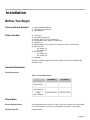
Before You Begin
Tools and Parts Needed 1) Phillips Head Screwdriver
2) Drill with 1/4” (6.35mm) bit
3) Tape Measure
Parts Included 1) Foam tape
2) Hold down brackets (4)
3) Screws, #10-32 x 2 1/2” (63.8mm) (4)
4) Sheet Metal Screws, #8 x 3/8” (9.5mm) (4)
5) Washers (4)
6) Rubber Grate Foot (1 extra foot is included for future use if required)
7) Burner Grates
30” models: (2)
36” models (3)
8) Burner Caps
30” models: (4)
36” models: (5)
9) Regulator
If parts are missing or damaged, call the number or write to the address listed
inside the cover.
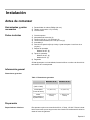
General Information
Overall Dimensions
Preparation
Electrical Requirements This appliances requires a 60 Hz, 15 Amp, 120 VAC connection. Plan the installa-
tion so that the power connection is accessible from the front of the cabinet.
Gas Requirements Supply Pressure:
Installation
Table 1: Overall Dimensions
30” Models 36” Models
Width
(Side to Side)
31” (787.4 mm) 37” (939.8 mm)
Depth
(Front to Back)
21” (533.4 mm) 21” (533.4 mm)
Height
(Top to Bottom)
4” (Below Countertop) 4” (Below Countertop)

English 4
• Natural Gas - 6 inches water column (14.9 Millibars) minimum.
• Propane Gas -11 inches water column (27.4 Millibars) minimum.
The propane gas tank must be equipped with its own high pressure regulator in
addition to the pressure regulator supplied with this unit. The cooktop is shipped
from the factory for use with natural gas. For use with LP conversion kit – Model
NEZ10
56, must be purchased separately. A qualified
technician or installer must
do th
e conversion.
Note: NGP model cooktops cannot be converted for LP use.
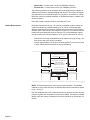
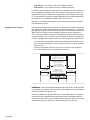
Cabinet Requirements Dimension requirements in Figs. 1 & 2 are for combustible surfaces. When the
surface is protected by a material listed by UL as a Floor Protector and Wall
Shield covered with not less than No. 28 MSG sheet metal 0.015 inch (0.38mm)
stainless steel, 0.024 inch (0.6mm) aluminum or copper, it is considered noncom-
bustible and some dimensions may be reduced. For a noncombustible surface
over the cooktop, the minimum clearance is 24" (61cm) rather than 30" (76cm) .
• Instructions are based on standard American cabinets 36" high (91cm) x 24"
deep (61cm) with a 25" (63cm) countertop.
• Provide approximately a 10 square inch opening (65cm
2
) in the toe kick area
or other cabinet area for adequate air inlet to the cabinet.
NOTE: All measurements given have to be precisely followed. If nonstandard
cabinets are used, make sure they are installed with minimum dimensions shown
in fig. 1 and fig. 2.
Plan the installation of the unit so that the power cord, gas shut-off valve and gas
pressure regulator are accessible from the front of cabinet. If a drawer is installed
directly under the cooktop, its depth (front to back) should be no greater than 15"
(38cm).
Figure 1: Installed Dimensions (from cooktop edges)
Depth from Back Wall
Cabinet 13" (33cm) max.
Hood Depth - 24" (61cm) max.
Centered Over Cooktop
Rear Wall - 1-3/4"(4cm)
Right Side
3" (8cm) min.
Left Side
6" (15cm) min.
18" (46cm) min.
Above Counter - 30" (76 cm) min. to
Combustible Surface
NGT(P)7x - 30" (76cm) min.
NGT(P)9x - 36" (91cm) min.

English 5
Countertop Requirements
Mounting Requirements Use the mounting brackets supplied. See “Attach Brackets to the Cooktop” on
page 6. and “Install the Cooktop” on page 6 for further details.
Ventilation Recommendations We strongly recommend the installation of a ventilation hood above this appli-
ance. The hood must be installed according to instructions furnished with the
hood.
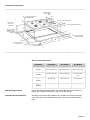
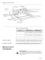
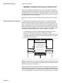
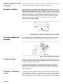
Figure 2: Cutout Dimensions
21” (533.4 mm) cooktop depth
4” (101.6 mm) Below Countertop
to Left Side Wall
7-3/8” (187.8 mm) Min.
2-1/4” (57.2 mm) Min. to
Counter Front
Clearance From
6” (152.4 mm)
Min. to Left
1-3/4” (44.5 mm) Min. to
Combustible Wall
to Right Side Wall
to
Right Side
Wall
Side Wall
Cooktop to Start
of Radius
4-3/8” (111.6 mm) Min.
3” (76.2 mm) Min.
1/8” (3.5 mm) Min.
Table 2: Cutout Dimensions
# Cooktop 30” Models 36” Models 45” Models
A
Cutout
19-1/8” to 19-7/8”
(486.1 to 505.6 mm)
19-1/8 to 19-7/8”
(486.1 to 505.6 mm)
19-1/8 to 19-7/8”
(486.1 to 505.6 mm)
B
Cutout
28-5/8” to 29-3/8”
(727.2 to 746.6 mm)
34-5/8” to 35-3/8”
(879.6 to 899 mm)
43-15/16” to 44-1/2”
(1116.2 to 1130.6
mm)
C
Corner
30” (762 mm) 36” (914.4 mm) 45” (1143 mm)
D
Overall
31” (787.4 mm) 37” (939.8 mm) 46” (1168.4 mm)

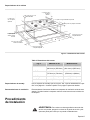
English 6
Installation
Procedure
WARNING: To avoid electrical shock hazard, before installing the
cooktop, switch power off at the service panel and lock the panel to
prevent the power from being switched on accidentally.
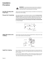
Seal the Cooktop with
Foam Tape
Apply the foam tape packaged with the cooktop to underside of the cooktop along
the perimeter before installing.
Prepare the Countertop Cut out the countertop per the dimensions shown in section Countertop Cutout
Dimensions above. For solid surface material installations such as Surell™ and
Corian®, consult with solid surface manufacturer. Apply heat reflective tape such
as Scotch Aluminum Foil Tape #425 or #427 around the cutout so that it folds
over on the top and sides. Do not wrap the tape underneath the cooktop. Be sure
the tape extends beyond the outermost flange of the cooktop. All corners should
be covered with tape.
Attach Brackets to the
Cooktop
Attach clamps of the hold-down brackets packaged with the cooktop to the rough-
in box. Use the washer and screws provided.
Install the Cooktop Insert cooktop into the cutout. Adjust hold-down brackets to desired position and
tighten screws to rough-in box. Insert adjusting screw into clamp and secure cook-
top to countertop.
For solid surface material installations: Insert a wooden block between the end of
the screw and the bottom of the countertop. Do not overtighten adjusting screw.
Trim excess aluminum tape around cooktop flange.
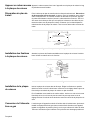
Figure 3: Counter Cutout – Solid Surface Countertops
Heat Reflective Tape
Cutout shows location
of Aluminum Reflective Tape
Section "A - A"
Figure 4: Attaching Hold-Down Brackets
Rough-in Box
Foam
Tap e
(Seal)
Adjusting
Screw
Adjusting
Screw
Clamp
Clamp
Wooden Block
(to be used with
solid surfacing
material, i.e.
Surell™ and
Corian®)

English 7
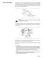
Connect Gas Supply The gas inlet to the unit is located at the right rear of rough-in box. After installing
a gas shut-off valve in an easily accessible location under the unit, install the pres-
sure regulator (supplied) to manifold pipe using Teflon tape on threads of manifold
pipe. To prevent possible damage to the gas pressure regulator, install it after the
rough-in box is in its permanent position.
CAUTION: Do not attempt any adjustment of the pressure regulator,
except conversion to propane.
Connect the gas supply line to the unit pressure regulator using a 1/2" flex gas line
connector between wall shut-off valve and pressure regulator (see complete pro-
cedure in Figure 6.)
Secure regulator to cooktop gas inlet using approved Teflon tape. Turn to hand
tighten plus 1/4 turn, not exceeding 1 turn for alignment.
Check supply line connections for leaks using a soap solution. Do not use a flame
of any sort.
1) Turn on gas.
2. Apply a non-corrosive leak detection fluid to all joints and fittings in the gas
connection between the shut-off valve and the range. Include gas fittings and
joints in the range if connections may have been disturbed during installation.
Bubbles appearing around fittings and connections indicate a leak.
3. If a leak appears, turn off supply line gas shut-off valve and tighten connec-
tions.
4. Retest for leaks by turning on the supply line gas shut-off valve. When leak
check is complete (no bubbles appear), test is complete.
5. Wipe off all detection fluid residue.
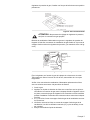
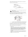
Figure 5: Rough-in Box Area
Figure 6: Gas and Electrical Location
Opening for Gas
Connection and
Electrical Cord
for 30” models - 12-15/16“ (312.8 mm)
for 36” models - 15-15/16“ (389 mm)
for 45” models - 20-3/8” (30 mm)
C of Cutout
L
1/2”
Female Pipe
Threads
Receptacle
Supply Cord
120 V
C of Wall
L
Flex Gas Line
Rough-in Box
Pressure
Regulator
Shows
Direction of
Gas Flow
Gas Shut-Off Valve
Cabinet Floor
Gas Stubout

English 8
Important Notes for Gas Connection:
• The appliance and its individual gas shutoff valve must be disconnected from
the gas supply piping system during any pressure testing of that system at
test pressures in excess of 1/2 psig (3.5kPa).
• The appliance must be isolated from the gas supply piping system by closing
its individual manual shut-off valve during any pressure testing of the gas sup-
ply piping system at test pressures equal to or less than 1/2 psi (3.5kPa).
Connect Electrical
Supply
Before connecting 5-foot (1.5 m) supply cord to wall receptacle, make certain that
gas shutoff valve and all burner controls are in OFF position.
Final Check After electrical connection is complete, place each burner cap in correct sized
notched position and check operation of electric igniters. Check flame characteris-
tics. Flame should be blue with no yellow tip.
Before Calling
Service
If the elements do not heat or if the indicator “on” light does not glow, check the
power source to see if a fuse has blown or if the circuit breaker has tripped.
Refer to the Warranty in the Use and Care Manual. See Use and Care manual for
troubleshooting information.
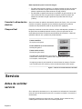
Figure 7: Checking Flame Characteristics
Yellow Flames:
Further adjustment is required.
Yellow Tips on Outer Cones:
Normal for LP Gas.
Soft Blue Flames:
Normal for Natural Gas.
If the flame is completely or mostly yellow,
verify that the regulator is set for the correct fuel. After adjustment, retest.
Some yellow streaking is normal during the initial start-up. Allow unit to operat
e
4-5 minutes and re-evaluate before making adjustments.
Service

English 9
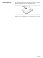
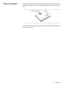
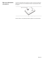
Product Data Plate The data plate shows the model and serial number of your cooktop. It is located in
the center front area of the rough-in box, underneath the cooktop.
Keep your invoice or escrow papers for warranty validation if service is needed.
Figure 8: Data Plate Location
Data Plate
Page is loading ...
Page is loading ...
Page is loading ...
Page is loading ...
Page is loading ...
Page is loading ...
Page is loading ...
Page is loading ...
Page is loading ...
Page is loading ...

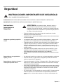
Seguridad. . . . . . . . . . . . . . . . . . . . . . . . . . . . . . . . . . . . . . . . . . . . . . . . . . 1
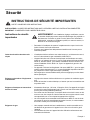
Instrucciones Importantes de Seguridad . . . . . . . . . . . . . . . . . . . . . . . . . . . . . . . . . . . . . . . . . . . . 1
Instalación . . . . . . . . . . . . . . . . . . . . . . . . . . . . . . . . . . . . . . . . . . . . . . . . . 3
Antes de comenzar . . . . . . . . . . . . . . . . . . . . . . . . . . . . . . . . . . . . . . . . . . . . . . . . . . . . . . . . . . . . 3
Procedimiento de Instalación . . . . . . . . . . . . . . . . . . . . . . . . . . . . . . . . . . . . . . . . . . . . . . . . . . . . 5
Servicio . . . . . . . . . . . . . . . . . . . . . . . . . . . . . . . . . . . . . . . . . . . . . . . . . . . 8
Antes de solicitar servicio . . . . . . . . . . . . . . . . . . . . . . . . . . . . . . . . . . . . . . . . . . . . . . . . . . . . . . . 8
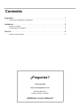
Contenido
¿Preguntas?
1-800-944-2904
www.boschappliances.com
5551 McFadden Ave.
Huntington Beach, CA 92649
¡Estámos a sus órdenes!
Page is loading ...
Page is loading ...
Page is loading ...
Page is loading ...
Page is loading ...
Page is loading ...
Page is loading ...
Page is loading ...
Page is loading ...

5551 McFadden Avenue, Huntington Beach, CA 92649 • 800/944-2904 • www.boschappliances.com
9000065787 (ECO# 5V0L94) • 10037 Rev C • 02/
11 © BSH Home Appliances Corporation 2011 • Litho in USA
-
 1
1
-
 2
2
-
 3
3
-
 4
4
-
 5
5
-
 6
6
-
 7
7
-
 8
8
-
 9
9
-
 10
10
-
 11
11
-
 12
12
-
 13
13
-
 14
14
-
 15
15
-
 16
16
-
 17
17
-
 18
18
-
 19
19
-
 20
20
-
 21
21
-
 22
22
-
 23
23
-
 24
24
-
 25
25
-
 26
26
-
 27
27
-
 28
28
-
 29
29
-
 30
30
-
 31
31
-
 32
32


Ask a question and I''ll find the answer in the document
Finding information in a document is now easier with AI
in other languages
- français: Bosch NGT942UC/02 Guide d'installation
- español: Bosch NGT942UC/02 Guía de instalación
Related papers
-
Bosch NGMP077UC User manual
-
Bosch NGT Series Installation guide
-
-
Bosch NGM5455UC/01 Installation guide
-
-
-
-
Bosch NEM7360UC/02 Installation guide
-
Bosch NGP935UC/01 Installation guide
-
Other documents
-
Siemens ET4955UC/02 User manual
-
Thermador SGSL365KS Installation guide
-
-
Thermador SGSP365TS Installation guide
-
Thermador SGSP305TS Installation guide
-
-
-
Bosch Benchmark NGMP677UC Installation guide
-
Bosch Benchmark NGMP077UC Installation guide
-
Thermador PCG366G User manual