© 2013 Pentair, Ltd. All Rights Reserved. HYD820 (Rev. 03/04/13)
293 WRIGHT STREET, DELAVAN, WI 53115 WWW.HYDROMATIC.COM
PH: 8889578677
OWNER’S MANUAL
Preplumbed Sump Pump System
NOTICE D’UTILISATION
Système de pompage de puisard
prêt à brancher
MANUAL DEL USUARIO
Sistema de bomba de sumidero con
conexión de plomería
5619 0507
CSS-3D, CSS-3V
Installation/Operation/Parts
For further operating, installation,
or maintenance assistance:
Call 1-888-957-8677
English ........................ Pages 2-10
Installation/Fonctionnement/Pièces
Pour plus de renseignements
concernant l’utilisation,
l’installation ou l’entretien,
Composer le
1 (888) 957-8677
Français .................. Pages 11-19
Instalación/Operación/Piezas
Para mayor información sobre el
funcionamiento, instalación o
mantenimiento de la bomba:
Llame al 1-888-957-8677
Español .................. Paginas 20-28

Safety 2
SAFETY INFORMATION
Carefully read and follow all safety
instructions in this manual or on pump.
This is the safety alert symbol. When you see this
symbol on your pump or in this manual, look for one of
the following signal words and be alert to the potential for
personal injury!
warns about hazards that will cause serious
personal injury, death or major property damage if ignored.
warns about hazards that can cause serious
personal injury, death or major property damage if
ignored.
warns about hazards that will or can cause
minor personal injury or property damage if ignored.
The word NOTICE indicates special instructions which are
important but not related to hazards.
1. Read these rules and instructions carefully. Failure to
follow them could cause serious bodily injury and/or
property damage.
2. Check your local codes before installing. You must
comply with their rules.
Hazardous voltage. Can shock, burn or kill.
During operation the pump is in water. To avoid fatal
shocks, proceed as follows if pump needs servicing:
3A. Disconnect power to outlet box before unplugging
pump.
3B. Unplug the pump before handling or servicing it.
3C. Take extreme care when changing fuses. Do not stand
in water or put your finger in the fuse socket.
3D. Do not modify the cord and plug. When using the
cord and plug, plug into a grounded outlet only. When
wiring to a system control, connect the pump ground
lead to the system ground.
4. Do not run the pump dry. Dry running can overheat
the pump (causing burns to anyone handling it), and
will void the warranty.
5. The pump normally runs hot. To avoid burns when
servicing pump, allow it to cool for 20 minutes after
shutdown before handling it.
6. The pump is permanently lubricated. No oiling or
greasing is required in normal operation.
7. Do not install the basin and pump in any location
classified as hazardous by the United States National
Electrical Code (NEC), or by the Canadian Electrical
Code (CEC), where applicable.
California Proposition 65 Warning
This product and related accessories contain
chemicals known to the State of California to cause
cancer, birth defects or other reproductive harm.
PUMP SPECIFICATIONS
Power Supply Required ............................ 115V, 60 Hz
Individual Branch Circuit Required .................. 15 Amps
Maximum Liquid Temperature .................. 120°F (50°C)
Discharge Adapter ...................................... 1-1/2" NPT
DESCRIPTION
The Hydromatic Sump Pump System, Model Number
CSS-3D or CSS-3V, is ideal for basement and cellar
installations. It includes a submersible sump pump and
a corrosion-resistant sump basin and lid. The pump
features a flush-mount system for maximum discharge of
the basin. All components of the sump pump system are
preassembled at the factory for easy installation.
This submersible pump is designed for sump drainage,
dewatering and flood control. The pump has built-in
thermal overload protection and an automatic reset. The
mechanical seal and ball bearings on the motor shaft are
permanently lubricated.
This system is designed for residential use only. The
supplied hardware kit includes a rubber inlet hub, a
cord grommet and an exterior check valve. No special
tools or sealants are required.
NOTICE: This system is not designed for applications
involving salt water or brine! Use with salt water or brine
will void warranty.
Pump water only with this pump.
PUMP, MOTOR, SWITCH & CORD SPECIFICATIONS
Individual Switch Setting in inches (mm) Discharge
Motor Motor Full Branch Circuit Cord Length Adapter
HP Load Amps Required (Amps) in ft. (m) On Off Size
.30 8.0 15 10 (3) 8 (203) 3-1/2 (89) 1-1/2
"
PERFORMANCE
GPH (LPH) AT TOTAL FEET (METERS)
OF LIFT
Model 5 (1.5 m) 10 (3 m) 15 (4.6 m) 20 (6.1 m)
25 ft
CSS-3D, 2,820 2,280 1,800 1,020 (7.6 m)
CSS-3V (10,675) (8,631) (6,814) (3,861)
No flow
at height
shown below
*For performance at maximum temperature see Catalog.

Description / Installation 3
INSTALLATION
Piping
Piping must not be smaller than pump discharge.
Electrical
Hazardous voltage. Can shock, burn, or
kill. When installing, operating, or servicing this pump,
follow the safety instructions listed below.
Do not lift pump by the power cord. See “Cord Lift
Warning” on Page 5.
1. DO NOT splice the electrical power cord.
2. DO NOT allow the electrical cord plug to be
submerged.
3. DO NOT use extension cords. They are a fire hazard
and can reduce voltage sufficiently to prevent
pumping and/or damage motor.
4. DO NOT handle or service the pump while it is
connected to the power supply.
5. DO NOT remove the grounding prong from the plug
or modify the plug. To protect against electrical shock,
the power cord is a three-wire conductor and includes
a 3-prong grounded plug. Plug the pump into a 3-wire,
grounded, grounding-type receptacle. Connect the
pump according to the NEC or CEC and local codes.
The pump is plugged into an automatic float/diaphragm
switch for automatic operation. The pump will run
continuously when plugged directly into an electrical
outlet.
Connect or wire pump to its own individual branch circuit
with no other outlets or equipment in the circuit. Size
fuses or circuit breakers according to the “Pump, Motor,
Switch and Cord Specifications” chart.
Risk of electrical shock and fire. Be sure
that power supply information (Voltage/ Hertz/Phase)
in this manual matches incoming power supply exactly.
Install pump according to all electrical codes that apply.
NOTICE: Proper ventilation is needed to prevent negative
basin pressure and to provide air within the basin.
The basin should be located at the lowest place in the
basement or area to be drained. Floor drains from other
areas in the basement may be tiled into the basin. Drain
tile around a house foundation may also be tiled into the
basin, effectively removing water and relieving pressure
from this area.
Basin covers are used to exclude refuse from the basin.
Limited Warranty
HYDROMATIC warrants to the original consumer purchaser (“Purchaser” or “You”) of HYDROMATIC Sump Pumps,
Effluent Pumps, Sewage Pumps (other than 2-1/2”), and Package Systems, that they will be free from defects in material and
workmanship for the Warranty Period of 36 months from date of manufacture.
Our warranty will not apply to any product that, in our sole judgement, has been subject to negligence, misapplication,
improper installation, or improper maintenance. Without limiting the foregoing, operating a three phase motor with single phase
power through a phase converter will void the warranty. Note also that three phase motors must be protected by three-leg,
ambient compensated, extra-quick trip overload relays of the recommended size or the warranty is void.
Your only remedy, and HYDROMATIC’s only duty, is that HYDROMATIC repair or replace defective products (at
HYDROMATIC’s choice). You must pay all labor and shipping charges associated with this warranty and must request warranty
service through the installing dealer as soon as a problem is discovered. No request for service will be accepted if received after
the Warranty Period has expired. This warranty is not transferable.
EXCEPTIONS: Hydromatic Special Application Pumps, Battery Back-Up Sump Pumps, Filtered Effluent Pumps, Grinder
Pumps, and 2-1/2” Sewage Pumps are warranted for a period of 12 months from date of purchase or 18 months from date of
manufacture, whichever comes first.
HYDROMATIC SHALL NOT BE LIABLE FOR ANY CONSEQUENTIAL, INCIDENTAL, OR CONTINGENT
DAMAGESWHATSOEVER.
THE FOREGOING LIMITED WARRANTIES ARE EXCLUSIVE AND IN LIEU OF ALL OTHER EXPRESS AND IMPLIED
WARRANTIES, INCLUDING BUT NOT LIMITED TO IMPLIED WARRANTIES OF MERCHANTABILITY AND FITNESS FOR
A PARTICULAR PURPOSE. THE FOREGOING LIMITED WARRANTIES SHALL NOT EXTEND BEYOND THE DURATION
PROVIDED HEREIN.
Some states do not allow the exclusion or limitation of incidental or consequential damages or limitations on the duration of an
implied warranty, so the above limitations or exclusions may not apply to You. This warranty gives You specific legal rights and
You may also have other rights which vary from state to state.
This Limited Warranty is effective June 1, 2011 and replaces all undated warranties and warranties dated before June 1, 2011.
HYDROMATIC
293 Wright Street, Delavan, WI 53115
Phone: 888-957-8677 • Fax: 800-426-9446 • Web Site: hydromatic.com

Installation / Operation 4
Installation Instructions. See Figure 1.
1. Dig the hole for the basin and the sub-base. The hole
must be deep enough so the top of the basin is flush
with the finished floor. Refer to Figure 1.
NOTICE: The sub-base should include 4" of sand or
gravel. The maximum diameter of crushed rock should
be 1/2". The recommended maximum diameter of pea
gravel is 3/4".
2. Level the sub-base out until it is smooth. Sharp rock
can damage the basin.
3. Reach into the inlet hole to retrieve the hardware kit.
Locate the cord grommet in the hardware kit.
4. Reach into the inlet hole again to pull the power cords
up through the cord grommet hole in the cover. Press
the cords into the cord grommet and install the
grommet in the cover.
5. Locate the inlet hub in the hardware kit, and snap it
into the inlet hole.
6. Install the basin on top of the sub-base.
7. Insert a 4" inlet pipe through the inlet hub. Insert it 2"
into the basin. Dish soap can be used to lubricate the
inlet hub. If necessary, file the sharp edges of the pipe
to prevent damage to the hub.
NOTICE: The inlet pipe should pitch down to the basin
inlet at 1/4" per foot. This will cause the water to run
into the basin.
8. Backfill around the basin with crushed rock, with a
maximum diameter of 1/2", or use pea gravel.
9. Install a 1-1/2" discharge pipe into the 1-1/2" FNPT
discharge flange.
10. Install a 2" vent pipe into the 2" FNPT threaded vent
flange. The vent pipe must go through the roof of the
building or it can be connected to an existing vent
pipe. The sump basin must be vented.
NOTICE: Proper ventilation is needed to prevent
negative basin pressure and to provide the necessary
air
within the basin.
11. Install the 1-1/2" check valve (supplied) in the
discharge pipe. See Figure 1. Make certain the flow
indicating arrow points away from the pump. This
check valve will keep the water from running back into
the basin when the pump is not running.
NOTICE: To prevent clogging the pump, clear basin
of any debris if you remove the cover during or after
installation. Unplug the pump first.
12. Plug the pump into a properly grounded outlet.
13. Check the operation by filling the basin with water
and observing pump operation through one complete
cycle. Make sure that no parts of the assembly interfere
with the float.
Failure to make this operational check may
lead to improper operation, premature failure, and
flooding.
OPERATION
NOTICE: The shaft seal depends on water for lubrication
and cooling. Do not operate the pump unless it is
submerged in water as the seal may be damaged if allowed
to run dry. Allowing the pump to run dry will void the
warranty.
An automatic overload protector in the motor will
protect the motor from burning out due to overheating/
overloading. When the motor cools down, the overload
protector will automatically reset and start the motor.
If the overload trips frequently, check for the cause. It
could be a stuck impeller, wrong/low voltage, or an
electrical
failure in the motor. If an electrical failure in the motor is
suspected, have it serviced by a competent repairman.
4" Inlet Pipe
Slope @ 1/4"
Per Foot
4" Snap-in
Inlet Hub
Cord Grommet
Discharge
Flange
Vent
Flange
Floor
1-1/2" Discharge
Pipe
Vent Pipe – Extend vent
through roof or connect
to existing vent.
Plug the Float Switch
into a Properly
Grounded Outlet.
Check Valve
Purchase inlet, vent and
discharge pipes locally.
5620 0507
Figure 1: Typical Installation
The pump is permanently lubricated. No oiling or greasing
is required.
NOTICE: The pump will not remove all water. For
extended operation, water depth must be at least 5" (13
cm) to prevent motor overheating.

Operation / Maintenance 5
Airlocks
When a pump airlocks, it runs but does not move any
water. An airlock will cause the pump to overheat and
fail. The discharge pipe is plumbed with a predrilled anti-
airlock hole. Leakage from the anti-airlock hole is normal
during pump operation.
Operational Check
Vertical Float Switch (CSS-3V Only)
1. Fill the sump with the correct amount of water to
check the operation and tightness of the connections.
During the first automatic cycle, it may take 30
seconds or more before the pump is primed and
pumping. The pump will start as indicated in the
“Pump, Motor, Switch and Cord Specifications” table
on Page 2.
2. Check the turn-off position. The pump will stop
approximately as indicated in the “Pump, Motor,
Switch and Cord Specifications” table on Page 2.
3. If the pump does not operate, check the electrical
service.
The vertical float has a short range of motion along a
vertical rod, which helps prevent the float from sticking.
On
Off
5621 0507
Diaphragm Pressure Switch (CSS-3D Only)
1. Fill the basin with enough water to cover the pump.
Water pressure increases as the water level rises,
engaging the switch and turning on the pump.
2. The switch will turn the pump off when the water level
drops.
This mechanism should never stick because the diaphragm
switch has no float. The switch is also not easily triggered
by water rushing into the basin, which helps extend the
life of the switch.
On
Off
Water
Level
5622 0507
MAINTENANCE
Hazardous voltage. Can shock, burn, or kill.
Before removing the pump from the basin for service,
always disconnect electrical power to the pump and the
control switch. Do not lift the pump by the power cord.
See the “Cord Lift Warning” below.
NOTICE: To prevent clogging the pump, clear basin
of any debris if you remove the cover during or after
installation. Unplug the pump first.
NOTICE: The pump should only be serviced by trained
personnel. There are no consumer serviceable parts inside
the pump.
Disconnect the discharge and vent pipes from the unit,
remove the four basin cover bolts, and then lift the pump
out of the basin using the pump handles.
DO NOT attempt to open the pump further than removing
the base and bottom plate.
The pump motor housing contains a special lubricating oil
which should be kept clean and free of water at all times.
The sump basin and cover, pump, and piping should be
protected from freezing temperatures.
1. Attempting to lift or support pump by power
cord can damage cord and cord connections.
2. Cord may pull apart, exposing bare wires
with possibility of fire or electrical shock.
3. Lifting or supporting pump by power cord
will void warranty.
4. Use lifting ring on top of pump for all lifting/
lowering of pump. Disconnect power to
pump before doing any work on pump or
attempting to remove pump from sump.
Lift by
handle
5623 0507
Risk of electrical shock.
Can burn or kill.
Do not lift pump by
power cord.
WARNING
CORD LIFT WARNING

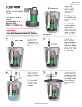
TO CLEAN THE IMPELLER
Follow the steps shown below. To reassemble pump,
reverse the sequence.
Risk of electrical shock. Can burn or
cause death.
Before removing the pump from the sump for service,
always disconnect the electrical power source to the
pump. Do not raise, lower or carry the pump by the power
cord. Use the lifting ring provided on the pump.
Cleaning 6
5624 0507
Base
Base
Screws
Bottom Plate
Pump Assembly
Lift the Pump out of
the Sump Pit by
the Lifting Ring.
3.
Disconnect the discharge and vent
pipes, and remove basin cover. Be
sure you do not damage the seal ring.
2.
Remove the Screws that hold the
Base to the Pump Assembly.
Remove the Bottom Plate and
clean out the Impeller.
4.
Impeller
location
Unplug the Pump.1.
Unplug the Piggyback Plug
from the Float Switch.
Figure 2: Impeller Cleaning

Parts 7
3
13
4
7
8
6
12
11
10
9
1
A.
2
5
B.
Fold tab
over cover.
2
14
1A
1A
5625 0507
Drowning risk to small children.
Do not leave small children
unattended near basin if lid is
off of basin.
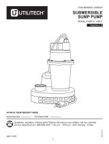
Key Part
No. Description Qty. CSS-3V
1A Basin Cover Assembly 1 PW73-65P
(Includes Nos. 1-8)
1 Basin Cover 1 -
2 Square Cut O-Ring 2 -
3 Vent Flange, 2" 1 -
4 Basin Bolt 8 -
5 Flat Washer 8 -
6 Discharge Flange, 1-1/2" 1 -
7 Cord Grommet 1 -
8 Seal Ring 1 PW73-71
9 Inlet Hub, Snap-In 1 PW73-67
10 Sump Basin 1 -
11 Sump Pump 1 522480007
12 Discharge Pipe 1 U37-689P
13 Check Valve 1 PW12-260
14 Vertical Float Switch 1 13869-510-5
REPAIR PARTS – PRE-PLUMBED SYSTEMS

Parts 8
3
14
4
7
8
6
13
11
10
9
1
A.
2
1A
1A
5
B.
Fold tab
over cover.
2
12
5626 0507
Key Part
No. Description Qty. CSS-3D
1A Basin Cover Assembly 1 PW73-65P
(Includes Nos. 1-8)
1 Basin Cover 1 -
2 Square Cut O-Ring 2 -
3 Vent Flange, 2" 1 -
4 Basin Bolt 8 -
5 Flat Washer 8 -
6 Discharge Flange, 1-1/2" 1 -
7 Cord Grommet 1 -
8 Seal Ring 1 PW73-71
9 Inlet Hub, Snap-In 1 PW73-67
10 Sump Basin 1 -
11 Sump Pump 1 522480007
12 Diaphragm Switch 1 12752-000-5
13 Discharge Pipe 1 FP0026-1
14 Check Valve 1 PW12-260
REPAIR PARTS – PRE-PLUMBED SYSTEMS
Drowning risk to small children.
Do not leave small children
unattended near basin if lid is
off of basin.

Parts 9
1
2
3
5
9
8
12
4
6
7
11
10
5627 0507
Key Part
No. Description Qty. Part No.
1 Ring Handle 1 8522-010-1
2 Pipe Plug 1 14077-000-1
3 Motor Assembly Housing* 1 -
4 Bottom Plate 1 8521-101-1
5 Pan Screw 5 14770-002-1
6 Base 1 8520-002-1
7 Impeller 1 8498-003-1
8 Rotating Seal 1 5484-003-1
9 Stationary Seal 1 5484-001-1
10 O-Ring 1 834-030-1
11 Cord Nut 1 75-005-1
12 Power Cord 10' 1 14623-010-1
REPAIR PARTS – PUMP
* If motor fails, replace entire pump.

Troubleshooting 10
TROUBLES-REMEDIES
Sudden Starts. If the power is on to the pump when thermal overload resets, the pump may start without
warning. If you are working on the pump, you may get an electrical shock or the impeller may catch fingers or tools.
Disconnect the power before servicing the pump.
A. Pump fails to operate: 1. Check to be sure that power cord is securely plugged into outlet or securely wired
into controller or switch box. Disconnect power to outlet before handling pump
or motor.
2. Check to be sure you have electrical power.
3. Check that liquid fluid level is high enough to activate switch or controller.
4. Check to be sure that the anti-airlock vent hole in the pump discharge is not plugged.
5. Check for blockage in pump inlet, impeller, check valve or discharge pipe.
6. Disconnect the pump from the power source for a minimum of 30 minutes to allow
the motor to cool and to protect yourself from sudden starts. See Warning above.
Check for the cause of overheating. Pump is running dry because the float switch
is caught up on something. Inlet pipe is plugged. Outlet pipe is plugged.
B. Pump fails to empty sump: 1. Be sure all valves in discharge pipe are fully open. Be sure check valve is installed
with flow arrow pointing AWAY from pump.
2. Clean out discharge pipe and check valve.
3. Check for blockage in pump inlet or impeller.
4. Pump not sized properly. A higher capacity pump may be required.
C. Pump will not shut off: 1. Check switch or controller automatic floats for proper operation and location.
See installation instructions for switch/controller.
2. If pump is completely inoperative or continues to malfunction, consult your
local serviceman.
D. Fuse blows or circuit breaker 1. Clogged inlet holes in pump base or clogged impeller. Unplug pump, remove it from
trips when pump starts: the basin, and clean.
2. Defective motor. Replace pump.
3. Fuse or circuit breaker too small. Connect pump to a 15 amp circuit.
E. Motor runs for a short time, 1. Clogged inlet holes in pump base or clogged impeller. Unplug pump, remove it from
then stops: the basin, and clean.
2. Defective motor. Replace pump.
Page is loading ...
Page is loading ...
Page is loading ...
Page is loading ...
Page is loading ...
Page is loading ...
Page is loading ...
Page is loading ...
Page is loading ...
Page is loading ...
Page is loading ...
Page is loading ...
Page is loading ...
Page is loading ...
Page is loading ...
Page is loading ...
Page is loading ...
Page is loading ...
/