Page is loading ...

UT-300R2 ADSL2/2+Modem
USER GUIDE
UTStarcom, Inc.

Copyright © 2004 UTStarcom, Inc. All rights reserved.
No part of this documentation may be reproduced in any form or by any means or
used to make any derivative work (such as translation, transformation, or
adaptation) without prior, express and written permission from UTStarcom, Inc.
UTStarcom, Inc. reserves the right to revise this documentation and to make
changes in content from time to time without obligation on the part of UTStarcom,
Inc. to provide notification of such revision or changes.
UTStarcom, Inc. provides this documentation without warranty of any kind, implied
or expressed, including but not limited to, the implied warranties of merchantability
and fitness for a particular purpose. UTStarcom may make improvements or
changes in the product(s) and/or the program(s) described in this documentation
at any time.
UNITED STATES GOVERNMENT LEGENDS:
If you are a United States government agency, then this documentation and the
software described herein are provided to you subject to the following:
United States Government Legend:
All technical data and computer software is
commercial in nature and developed solely at private expense. Software is
delivered as Commercial Computer Software as defined in DFARS 252.227-7014
(June 1995) or as a commercial item as defined in FAR 2.101(a) and as such is
provided with only such rights as are provided in UTStarcom's standard
commercial license for the Software. Technical data is provided with limited rights
only as provided in DFAR 252.227-7015 (Nov 1995) or FAR 52.227-14 (June
1987), whichever is applicable. You agree not to remove or deface any portion of
any legend provided on any licensed program or documentation contained in, or
delivered to you in conjunction with, this User Guide.
UTStarcom, the UTStarcom logo, PAS, mSwitch, Airstar, WACOS, Netman, Total
Control, and CommWorks are registered trademarks of UTStarcom, Inc. and its
subsidiaries. The UTStarcom name, AN-2000, and the CommWorks logo are
trademarks of UTStarcom, Inc. and its subsidiaries.
Other brand and product names may be registered trademarks or trademarks of
their respective holders.
Any rights not expressly granted herein are firmly reserved.

Contents
1 Overview......................................................................................... 1
Device Introduction ...................................................................................... 1
Features ...................................................................................................... 2
2 Installation Planning...................................................................... 5
Packing List ................................................................................................. 5
Interfaces Introduction ................................................................................. 6
Front Panel .............................................................................................. 6
Rear Panel............................................................................................... 7
Cable Connections....................................................................................... 7
Connecting the ADSL Line....................................................................... 7
Connecting the UT-300R2 to the Ethernet LAN........................................ 8
Computer to UT-300R2 Connection ......................................................... 9
Hub or Switch to UT-300R2 Connection................................................... 9
Power on ................................................................................................... 10
3 Before Configuring UT-300R2..................................................... 13
Set up TCP/IP on Your PC......................................................................... 13
Set up Proxy Service ................................................................................. 14
Configure IP Settings on Your PC.............................................................. 14
First Time Log on....................................................................................... 15
4 Web-based Management............................................................. 17
Summary................................................................................................... 17
Configuring the WAN Connection .............................................................. 19
Configuring a Bridged Connection for the WAN...................................... 21
Configuring a Routed/Bridged Connection for the WAN ......................... 24
Configuring a PPP Connection for the WAN........................................... 26
Dynamic IP Address for the WAN Connection........................................ 28

ii
Static IP Address for WAN......................................................................30
DHCP Configuration ...................................................................................32
DHCP Server Settings for the LAN..........................................................33
Use the UT-300R2 for DHCP..................................................................34
Disabling the DHCP Server.....................................................................34
DNS Server Setting ....................................................................................34
Configuring the LAN Connection.................................................................35
Save New Settings .....................................................................................37
5 Advanced Configuration / Network Management......................39
Virtual Server Configuration........................................................................41
Special Application Configuration ...............................................................45
Configure a Filter Rule-IP Filters.................................................................48
Configuring a Filter Rule- MAC Filters.........................................................53
Configuring a Filter Rule-URL Blocking.......................................................56
Configuring a Filter Rule-Domain Blocking..................................................59
Firewall.......................................................................................................62
DMZ ...........................................................................................................64
DDNS .........................................................................................................65
RIP .............................................................................................................66
6 Tools..............................................................................................67
Administrator’s Settings ..............................................................................67
Configure System Time ..............................................................................68
Save UT-300R2 Configuration Settings ......................................................69
Save Configuration File to PC.....................................................................70
Load Saved Configuration Files..................................................................71
Restore Factory Default Settings ................................................................72
Firmware Update........................................................................................72
7 UT-300R2 Status Information ......................................................75
Log.............................................................................................................75

iii
Traffic Statistics ......................................................................................... 76
Diagnostics................................................................................................ 77
8 Attachments ................................................................................. 79
Technical Specifications............................................................................. 79
Glossary .................................................................................................... 82

1
Overview
The UT-300R2 provides integrated voice and data services over
ADSL (Asymmetrical Digital Subscriber Loop) WAN (Wide Area
Network) connection.
Device Introduction
The UT-300R2 ADSL UT-300R2 is designed to provide a
simple and cost-effective ADSL Internet connection for
individual computers through the Ethernet ports, or use it to
bridge your Ethernet LAN to the Internet. The UT-300R2
combines the benefits of high-speed ADSL technology and LAN
IP management in one compact and convenient package.
ADSL technology enables many interactive multi-media
applications such as video conferencing and collaborative
computing.
The UT-300R2 is easy to install and use. The UT-300R2
connects to computers or an Ethernet LAN via a standard
Ethernet interface. The ADSL connection is made using
ordinary twisted-pair telephone line with standard connectors.
Multiple PCs can be networked and connected to the Internet
using a single Wide Area Network (WAN) interface and single
global IP address.
1

2 Chapter 1 Overview
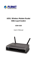
Figure 1
Device Appearance
Features
• Data rates up to 26 Mbps downstream
• Bridging and routing capabilities
•
PPP and tunneling features
• Firewall with Dynamic Host Configuration Protocol (DHCP),
Network Address Translation (NAT), Point-to-Point
Tunneling Protocol (PPTP), and Layer 2 Tunneling
Protocol (L2TP).
• Supports ADSL, ADSL2, ADSL2+
• DSL Forum TR-048-compliant DSL CPE auto-
configuration
• UPnP for seamless network interconnectivity
• Comprehensive networking protocol support includes
DHCP, PPPoE, PPPoA, and RIP
• Friendly web-based graphical user interface for
configuration and management

Chapter 1 Overview
3
• Supports up to eight simultaneous virtual connections for a
single ADSL account
• Supports T1.413 issue 2, G.dmt and G.lite standards
• Auto-handshake and rate adaptation for different ADSL
flavors
• Widest range of DSLAM interoperability
• Supports bridged Ethernet over ATM (RFC 2684)
• Upgradeable firmware through web

2
Installation Planning
Before installing the UT-300R2, you should gather information
and equipment needed to install the device, then Install the
hardware as instructed, connect the cables to the device and
power on the UT-300R2. Prior to accessing the web-based
software built into the UT-300R2, you should check the IP
settings on your computer and change them if necessary.
Packing List
Please check the package contents by comparing them with the
following list:
• One UT-300R2
• One telephone line
• One straight-through Ethernet Cable
• One Power Adapter
• One User CD-ROM
• One Splitter
2

6 Chapter 2 Installation Planning
Interfaces Introduction
Front Panel
Figure 2 Front Panel
Power
Steady green light indicates the unit is powered on.
When the device is powered off this remains dark.
Status
Lights steady green during power on self-test
(POST). Once the connection status has been
settled, the light will blink green. If the indicator
lights steady green after the POST, the system has
failed and the device should be rebooted.
ADSL:
Link/Act
Steady green light indicates a valid ADSL
connection. This will light after the ADSL
negotiation process has been settled. A blinking
green light indicates activity on the WAN (ADSL)
interface.
ETHERNET:
Link/Act
A solid green light indicates a valid link on startup.
This light blinks when there is activity currently
passing through the Ethernet port.

Chapter 2 Installation Planning
7
Rear Panel
Figure 3
Rear Panel
ADSL port -
Connect to the
ADSL line
Ethernet port - to your
PC’s Ethernet port
Factory Reset
Button
Power input - Connect
power adapter here
Cable Connections
After verifying proper environmental conditions such as
temperature, humidity and power supply, users may start the
cable connections as following.
Connecting the ADSL Line
Use the ADSL cable included with the UT-300R2 to connect it
to a telephone wall socket or receptacle. Plug one end of the
cable into the ADSL port (RJ-11 receptacle) on the rear panel of
the UT-300R2 and insert the other end into the RJ-11 wall
socket. If you are using a low pass filter device, follow the
instructions included with the device or given to you by your
service provider. The ADSL connection represents the WAN
interface, the connection to the Internet. It is the physical link to
the service provider’s network backbone and ultimately to the
Internet.

8 Chapter 2 Installation Planning
Connecting the UT-300R2 to the Ethernet LAN
The UT-300R2 may be connected to a single computer or
Ethernet device through the 10BASE-TX Ethernet port on the
rear panel. Any connection to an Ethernet concentrating device
such as a switch or hub must operate at a speed of 10/100
Mbps only. When connecting the UT-300R2 to any Ethernet
device that is capable of operating at speeds higher than
10Mbps, be sure that the device has auto-negotiation (NWay)
enabled for the connecting port.
Use standard twisted-pair cable with RJ-45 connectors. The RJ-
45 port on the UT-300R2 is a crossed port (MDI-X). Follow
standard Ethernet guidelines when deciding what type of cable
to use to make this connection. When connecting the UT-300R2
directly to a PC or server use a normal straight-through cable.
You should use a crossed cable when connecting the UT-
300R2 to a normal (MDI-X) port on a switch or hub. Use a
normal straight-through cable when connecting it to an uplink
(MDI-II) port on a hub or switch.
The rules governing Ethernet cable lengths apply to the LAN to
UT-300R2 connection. Be sure that the cable connecting the
LAN to the UT-300R2 does not exceed 100 meters.

Chapter 2 Installation Planning
9
Computer to UT-300R2 Connection
Figure 4
Computer to UT-300R2 Connection
You can connect the UT-300R2 directly to a 10/100BASE-TX
Ethernet adapter card (NIC) installed on a PC using the
Ethernet cable provided as shown in this diagram.
Hub or Switch to UT-300R2 Connection
Connect the UT-300R2 to an uplink port on an Ethernet hub or
switch with a straight-through cable as shown in the diagram
below:

10
Chapter 2 Installation Planning
Figure 5
Hub/Switch to UT-300R2 Connection
If you wish to reserve the uplink port on the switch or hub for
another device, connect to any on the other MDI-X ports (1x, 2x,
etc.) with a crossed cable.
Power on
1 To power on the UT-300R2, please follow the steps as
instructed:
2 Insert the AC Power Adapter cord into the power
receptacle located on the rear panel of the UT-300R2 and
plug the adapter into a suitable nearby power source.

Chapter 2 Installation Planning
11
3 You should see the Power LED indicator light up and
remain lit. The Status LED should light solid green and
begin to blink after a few seconds.

3
Before Configuring UT-300R2
The factory default settings of UT-300R2 optimized all functions
so as to enable it to operate on most network conditions.
Usually, for the users with simple network topology, the default
settings can meet the basic requirements and don’t need to
change. In order to access the web-based software built into
the UT-300R2, you should check the IP settings on your
computer and change them if necessary to access web-based
manager to configure the device.
Set up TCP/IP on Your PC
In order to configure your system to receive IP settings from the
UT-300R2 it must first have the TCP/IP protocol installed. If you
have an Ethernet port on your computer, it probably already has
TCP/IP protocol installed. Please follow the instructions to
check your IP protocol:
1 In Windows task bar, click the
Start
button, point to
Settings>Network and Dial-up Connection
> and click on
Local Connection.
2 Click on
Properties
> Select Internet Protocol (TCP/IP)
and then Click Properties.
3 Click on the button labeled use the following IP address,
then you can set the IP address and Subnet mask, for
example, 192.168.1.100 and 255.255.255.0.
3

14
Chapter 3 Before Configuring UT-300R2
Note:
If Internet Protocol (TCP/IP) does not display as an
installed component, you must install it.
Set up Proxy Service
In Windows Internet Explorer, you can check if a proxy server is
enabled using the following procedure:
1 Click on the
START
button, go to
Settings
and choose
Control Panel
.
2 In the
Control Panel
window, double-click on the
Internet
Options
icon
3 Click the Connections tab and click on the LAN Settings
button.
4 Verify that the “
Use proxy server
” option is NOT checked.
If it is checked, click in the checked box to deselect the
option and click OK.
Configure IP Settings on Your PC
To use the web-based management software, launch your web
browser software and use the LAN IP address of the UT-300R2
to access the management software. The default LAN IP
address of the UT-300R2 is used in the Address bar of your
web browser window. Type in
http://
followed by the default IP
address,
192.168.1.1
in the address
bar of the browser. The
URL in the address bar should read: http://192.168.1.1

Chapter 3 Before Configuring UT-300R2
15
First Time Log on
After inputting the forgoing IP address on URL address bar, a
new window appears prompting you for a user name and
password needed to gain access the web configuration
manager.
Figure 6
Log On Interface
Use the default system user name:
admin
and password:
admin for first time set up. You can change the password once
you have established the ADSL connection. The user name and
password allows any computer on the same subnet as the UT-
300R2 to access the web configuration manger. This password
can also be used to Telnet to the device through the Ethernet or
the Internet interfaces.

4
Web-based Management
Summary
When you successfully login the
Summary
directory button will
display the UT-300R2’s current connection status − both for the
WAN (Internet) and LAN (your home network) connections, as
shown below. You can begin the process of configuring your
ADSL modem/UT-300R2 by clicking on the
WAN
button in the
upper left-hand corner of the first Web page displayed.
4

18
Chapter 4 Web-based Management
Figure 7
Web Manager – First Page
Each tab displays menu buttons located in the left hand panel
of the web interface. The table below lists the menus for each
directory in the web manager.
/