
Part No. 2047371100R
ECM-3711 Series
VIA Eden V4 Micro Module
User’s Manual
1
st
Ed – 23 August 2006

ECM-3711 Series
2 ECM-3711 Series User’s Manual
FCC Statement
THIS DEVICE COMPLIES WITH PART 15 FCC RULES. OPERATION IS
SUBJECT TO THE FOLLOWING TWO CONDITIONS:
(1) THIS DEVICE MAY NOT CAUSE HARMFUL INTERFERENCE.
(2) THIS DEVICE MUST ACCEPT ANY INTERFERENCE RECEIVED INCLUDING
INTERFERENCE THAT MAY CAUSE UNDESIRED OPERATION.
THIS EQUIPMENT HAS BEEN TESTED AND FOUND TO COMPLY WITH THE LIMITS
FOR A CLASS "A" DIGITAL DEVICE, PURSUANT TO PART 15 OF THE FCC RULES.
THESE LIMITS ARE DESIGNED TO PROVIDE REASONABLE PROTECTION AGAINTST
HARMFUL INTERFERENCE WHEN THE EQUIPMENT IS OPERATED IN A
COMMERCIAL ENVIRONMENT. THIS EQUIPMENT GENERATES, USES, AND CAN
RADIATE RADIO FREQUENCY ENERGY AND, IF NOT INSTATLLED AND USED IN
ACCORDANCE WITH THE INSTRUCTION MANUAL, MAY CAUSE HARMFUL
INTERFERENCE TO RADIO COMMUNICATIONS.
OPERATION OF THIS EQUIPMENT IN A RESIDENTIAL AREA IS LIKELY TO CAUSE
HARMFUL INTERFERENCE IN WHICH CASE THE USER WILL BE REQUIRED TO
CORRECT THE INTERFERENCE AT HIS OWN EXPENSE.
Notice
This guide is designed for experienced users to setup the system within the shortest time.
For detailed information, please always refer to the electronic user's manual.
Copyright Notice
Copyright © 2006 Evalue Technology Inc., ALL RIGHTS RESERVED.
No part of this document may be reproduced, copied, translated, or transmitted in any form
or by any means, electronic or mechanical, for any purpose, without the prior written
permission of the original manufacturer.
Trademark Acknowledgement
Brand and product names are trademarks or registered trademarks of their respective
owners.

User’s Manual
ECM-3711 Series User’s Manual
3
Disclaimer
Evalue Technology Inc. reserves the right to make changes, without notice, to any product,
including circuits and/or software described or contained in this manual in order to improve
design and/or performance. Evalue Technology assumes no responsibility or liability for the
use of the described product(s), conveys no license or title under any patent, copyright, or
masks work rights to these products, and makes no representations or warranties that
these products are free from patent, copyright, or mask work right infringement, unless
otherwise specified. Applications that are described in this manual are for illustration
purposes only. Evalue Technology Inc. makes no representation or warranty that such
application will be suitable for the specified use without further testing or modification.
Life Support Policy
Evalue Technology’s PRODUCTS ARE NOT FOR USE AS CRITICAL COMPONENTS IN
LIFE SUPPORT DEVICES OR SYSTEMS WITHOUT THE PRIOR WRITTEN APPROVAL
OF Evalue Technology Inc.
As used herein:
1. Life support devices or systems are devices or systems which, (a) are intended for
surgical implant into body, or (b) support or sustain life and whose failure to perform,
when properly used in accordance with instructions for use provided in the labeling, can
be reasonably expected to result in significant injury to the user.
2. A critical component is any component of a life support device or system whose failure to
perform can be reasonably expected to cause the failure of the life support device or
system, or to affect its safety or effectiveness.
A Message to the Customer
Evalue Customer Services
Each and every Evalue’s product is built to the most exacting specifications to ensure
reliable performance in the harsh and demanding conditions typical of industrial
environments. Whether your new Evalue device is destined for the laboratory or the factory
floor, you can be assured that your product will provide the reliability and ease of operation
for which the name Evalue has come to be known.
Your satisfaction is our primary concern. Here is a guide to Evalue’s customer services. To
ensure you get the full benefit of our services, please follow the instructions below carefully.

ECM-3711 Series
4 ECM-3711 Series User’s Manual
Technical Support
We want you to get the maximum performance from your products. So if you run into
technical difficulties, we are here to help. For the most frequently asked questions, you can
easily find answers in your product documentation. These answers are normally a lot more
detailed than the ones we can give over the phone. So please consult the user’s manual
first.
To receive the latest version of the user’s manual; please visit our Web site at:
http://www.evalue-tech.com/
If you still cannot find the answer, gather all the information or questions that apply to your
problem, and with the product close at hand, call your dealer. Our dealers are well trained
and ready to give you the support you need to get the most from your Evalue’s products. In
fact, most problems reported are minor and are able to be easily solved over the phone.
In addition, free technical support is available from Evalue’s engineers every business day.
We are always ready to give advice on application requirements or specific information on
the installation and operation of any of our products. Please do not hesitate to call or e-mail
us.
Headquarters
Evalue Technology Inc.
7F, 228, Lian-cheng Road,
Chung Ho City, Taipei,
Taiwan
Tel : +886-2-8226-2345
Fax : +886-2-8226-2777
http://www.evalue-tech.com
E-mail: [email protected]
Europe Branch Office
Evalue Europe A/S
Stenholtsvej 13,
3480 Fredensborg,
Denmark
Tel : +45-7025-0310
Fax : +45-4975-5026
http://www.evalue-tech.com
E-mail: [email protected]
China Branch Office
Evalue Technology Shanghai Inc.
Room 909, 9F, Section B, No.900,
Yisan Road, Caohejing Hi-tech Park,
Shanghai 200233, China
Tel : +86-21-5423-4170
Fax : +86-21-5423-4171
http://www.evalue-tech.com
E-mail: [email protected]
US Branch Office
Evalue Technology Inc.
Suite 210, 200 Tornillo Way,
Tinton Falls, NJ 07712
USA
Tel: +1-732-578-0200
Fax: +1-732-578-0250
http://www.evalue-tech.com
E-mail: [email protected]

User’s Manual
ECM-3711 Series User’s Manual
5
Product Warranty
Evalue warrants to you, the original purchaser, that each of its products will be free from
defects in materials and workmanship for two years from the date of purchase.
This warranty does not apply to any products which have been repaired or altered by
persons other than repair personnel authorized by Evalue, or which have been subject to
misuse, abuse, accident or improper installation. Evalue assumes no liability under the
terms of this warranty as a consequence of such events. Because of Evalue’s high
quality-control standards and rigorous testing, most of our customers never need to use our
repair service. If any of Evalue’s products is defective, it will be repaired or replaced at no
charge during the warranty period. For out-of-warranty repairs, you will be billed according
to the cost of replacement materials, service time, and freight. Please consult your dealer
for more details. If you think you have a defective product, follow these steps:
1. Collect all the information about the problem encountered. (For example, CPU type and
speed, Evalue’s products model name, hardware & BIOS revision number, other
hardware and software used, etc.) Note anything abnormal and list any on-screen
messages you get when the problem occurs.
2. Call your dealer and describe the problem. Please have your manual, product, and any
helpful information available.
3. If your product is diagnosed as defective, obtain an RMA (return material authorization)
number from your dealer. This allows us to process your good return more quickly.
4. Carefully pack the defective product, a complete Repair and Replacement Order Card
and a photocopy proof of purchase date (such as your sales receipt) in a shippable
container. A product returned without proof of the purchase date is not eligible for
warranty service.
5. Write the RMA number visibly on the outside of the package and ship it prepaid to your
dealer.

ECM-3711 Series
6 ECM-3711 Series User’s Manual
Contents
1. Getting Started............................................................................................................9
1.1 Safety Precautions ....................................................................................................9
1.2 Packing List...............................................................................................................9
1.3 Document Amendment History ...............................................................................10
1.4 Manual Objectives...................................................................................................11
1.5 System Specifications .............................................................................................12
1.6 Architecture Overview .............................................................................................14
1.6.1 Block Diagram ................................................................................................................................ 14
1.6.2 VIA CN700 & VT8251 .................................................................................................................... 15
1.6.3 VIA VT1616 AC’97 Codec.............................................................................................................. 18
1.6.4 VIA VT1636 LVDS Transmitter ...................................................................................................... 19
1.6.5 VT1211 Super I/O .......................................................................................................................... 19
1.6.6 Ethernet.......................................................................................................................................... 20
1.6.7 Compact Flash Interface ................................................................................................................ 21
2. Hardware Configuration...........................................................................................22
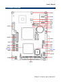
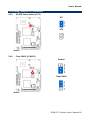
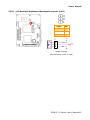
2.1 Product Overview....................................................................................................23
2.2 Installation Procedure .............................................................................................24
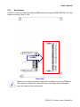
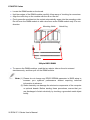
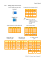
2.2.1 Main Memory.................................................................................................................................. 25
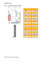
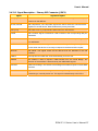
2.3 Jumper and Connector List .....................................................................................27
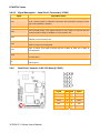
2.4 Setting Jumpers & Connectors ...............................................................................29
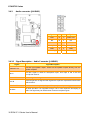
2.4.1 AT/ATX Power Select (JAT1)......................................................................................................... 29
2.4.2 Clear CMOS (JCMOS1)................................................................................................................. 29
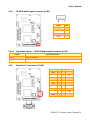
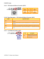
2.4.3 Audio connector (JAUDIO1)........................................................................................................... 30
2.4.4 CD-ROM Audio Input Connector (JCD1) ....................................................................................... 31
2.4.5 Serial Port 1 Connector (JCOM1) .................................................................................................. 31
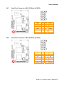
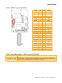
2.4.6 Serial Port Connector in RS-232 Mode (JCOM2) .......................................................................... 32
2.4.7 Serial Port Connector in RS-422 Mode (JCOM2) .......................................................................... 33
2.4.8 Serial Port Connector in RS-485 Mode (JCOM2) .......................................................................... 33
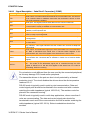
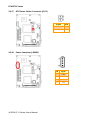
2.4.9 General Purpose I/O Connector (JDIO1)....................................................................................... 35
2.4.10 System Fan Connector (JFAN1)................................................................................................ 35
2.4.11 Primary IDE Connector (JIDE1)................................................................................................. 36
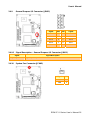
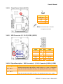
2.4.12 LCD Inverter Connector (JINV1)................................................................................................ 38
2.4.13 IrDA Connector (JIR1) ............................................................................................................... 39
2.4.14 PS/2 Keyboard & Mouse Connector (JKB1).............................................................................. 40
2.4.15 RJ-45 Ethernet (JLAN1, JLAN2)................................................................................................ 40
2.4.16 LVDS Connector (JLVDS1) ....................................................................................................... 41

User’s Manual
ECM-3711 Series User’s Manual
7
2.4.17 ATX Power Switch Connector (JPS1) ....................................................................................... 42
2.4.18 Power Connector (JPWR1)........................................................................................................ 42
2.4.19 Single Power Select (JSUS1) .................................................................................................... 43
2.4.20 USB Connector 0, 1, 2 & 3 (JUSB1, JUSB2)............................................................................. 43
2.4.21 VGA Connector (JVGA1) ...........................................................................................................44
2.4.22 LCD Backlight Brightness Adjustment Connector (JVR1)......................................................... 45
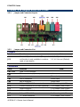
2.5 Audio / USB Daughter Board User’s Guide.............................................................46
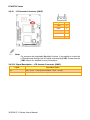
2.5.1 Jumper and Connector Layout....................................................................................................... 46
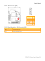
2.5.2 Jumper and Connector List ............................................................................................................ 46
2.5.3 Setting Jumper and Connector ...................................................................................................... 47
3. BIOS Setup................................................................................................................48
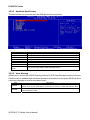
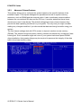
3.1 Starting Setup .........................................................................................................49
3.2 Using Setup ............................................................................................................50
3.3 Getting Help ............................................................................................................51
3.4 In Case of Problems................................................................................................51
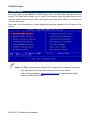
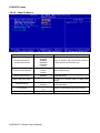
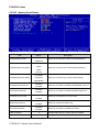
3.5 Main Menu ..............................................................................................................52
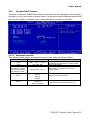
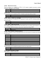
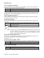
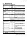
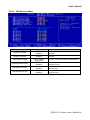
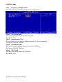
3.5.1 Standard CMOS Features.............................................................................................................. 53
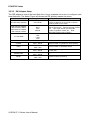
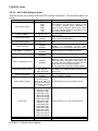
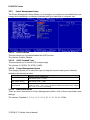
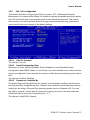
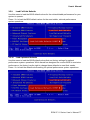
3.5.2 Advanced BIOS Features .............................................................................................................. 55
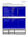
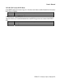
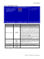
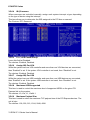
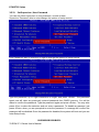
3.5.3 Advanced Chipset Features........................................................................................................... 60
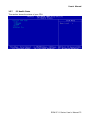
3.5.4 Integrated Peripherals.................................................................................................................... 65
3.5.5 Power Management Setup............................................................................................................. 70
3.5.6 PnP / PCI Configuration ................................................................................................................. 73
3.5.7 PC Health Status............................................................................................................................ 75
3.5.8 Frequency / Voltage Control .......................................................................................................... 76
3.5.9 Load Fail-Safe Defaults.................................................................................................................. 77
3.5.10 Load Optimized Defaults............................................................................................................ 77
3.5.11 Set Supervisor / User Password................................................................................................ 78
3.5.12 Save & Exit Setup ...................................................................................................................... 80
3.5.13 Exit Without Save....................................................................................................................... 80
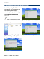
4. Drivers Installation ...................................................................................................81
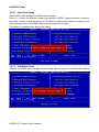
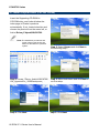
4.1 Install Chipset Driver (For VIA CN700) ...................................................................82
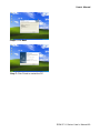
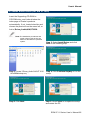
4.2 Install Display Driver (For VIA CN700)....................................................................84
4.3 Install Audio Driver (For VIA VT1616) .....................................................................85
4.4 Install Ethernet Driver (For Realtek RTL8111B)......................................................86
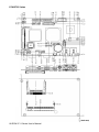
5. Measurement Drawing .............................................................................................87
Appendix A: BIOS Revisions..........................................................................................89
Appendix B: AWARD BIOS POST Messages ................................................................90
Overview............................................................................................................................91
Post Beep ..........................................................................................................................91
Error Messages .................................................................................................................91

ECM-3711 Series
8 ECM-3711 Series User’s Manual
1. CMOS BATTERY HAS FAILED .........................................................................................................91
2. CMOS CHECKSUM ERROR .............................................................................................................91
3. DISK BOOT FAILURE, INSERT SYSTEM DISK AND PRESS ENTER ............................................ 91
4. DISKETTE DRIVES OR TYPES MISMATCH ERROR - RUN SETUP.............................................. 91
5. DISPLAY SWITCH IS SET INCORRECTLY...................................................................................... 92
6. DISPLAY TYPE HAS CHANGED SINCE LAST BOOT ..................................................................... 92
7. EISA Configuration Checksum Error PLEASE RUN EISA CONFIGURATION UTILITY................... 92
8. EISA Configuration Is Not Complete PLEASE RUN EISA CONFIGURATION UTILITY ................... 92
9. ERROR ENCOUNTERED INITIALIZING HARD DRIVE.................................................................... 92
10. ERROR INITIALIZING HARD DISK CONTROLLER ..................................................................... 92
11. FLOPPY DISK CNTRLR ERROR OR NO CNTRLR PRESENT ................................................... 92
12. Invalid EISA Configuration PLEASE RUN EISA CONFIGURATION UTILITY .............................. 93
13. KEYBOARD ERROR OR NO KEYBOARD PRESENT ................................................................. 93
14. Memory Address Error at ... ........................................................................................................... 93
15. Memory parity Error at ................................................................................................................... 93
16. MEMORY SIZE HAS CHANGED SINCE LAST BOOT ................................................................. 93
17. Memory Verify Error at ... ............................................................................................................... 93
18. OFFENDING ADDRESS NOT FOUND ......................................................................................... 93
19. OFFENDING SEGMENT: ..............................................................................................................93
20. PRESS A KEY TO REBOOT ......................................................................................................... 94
21. PRESS F1 TO DISABLE NMI, F2 TO REBOOT ........................................................................... 94
22. RAM PARITY ERROR - CHECKING FOR SEGMENT ... ............................................................. 94
23. Should Be Empty But EISA Board Found PLEASE RUN EISA CONFIGURATION UTILITY....... 94
24. Should Have EISA Board But Not Found PLEASE RUN EISA CONFIGURATION UTILITY ....... 94
25. Slot Not Empty ............................................................................................................................... 94
26. SYSTEM HALTED, (CTRL-ALT-DEL) TO REBOOT ... ................................................................. 94
27. Wrong Board In Slot PLEASE RUN EISA CONFIGURATION UTILITY........................................ 95
28. FLOPPY DISK(S) fail (80) → Unable to reset floppy subsystem................................................... 95
29. FLOPPY DISK(S) fail (40) → Floppy Type dismatch..................................................................... 95
30. Hard Disk(s) fail (80) → HDD reset failed.................................................................................... 95
31. Hard Disk(s) fail (40) → HDD controller diagnostics failed.......................................................... 95
32. Hard Disk(s) fail (20) → HDD initialization error.......................................................................... 95
33. Hard Disk(s) fail (10) → Unable to recalibrate fixed disk............................................................. 95
34. Hard Disk(s) fail (08) → Sector Verify failed................................................................................ 95
35. Keyboard is locked out - Unlock the key. ....................................................................................... 95
36. Keyboard error or no keyboard present. ........................................................................................ 95
37. Manufacturing POST loop.............................................................................................................. 95
38. BIOS ROM checksum error - System halted. ................................................................................ 95
39. Memory test fail. ............................................................................................................................. 95
40. POST Codes .................................................................................................................................. 96

User’s Manual
ECM-3711 Series User’s Manual
9
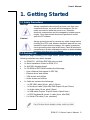
1. Getting Started
1.1 Safety Precautions
Warning!
Always completely disconnect the power cord from your
chassis whenever you work with the hardware. Do not
make connections while the power is on. Sensitive
electronic components can be damaged by sudden power
surges. Only experienced electronics personnel should
open the PC chassis.
Caution!
Always ground yourself to remove any static charge before
touching the CPU card. Modern electronic devices are very
sensitive to static electric charges. As a safety precaution,
use a grounding wrist strap at all times. Place all electronic
components in a static-dissipative surface or static-shielded
bag when they are not in the chassis.
1.2 Packing List
Before you begin installing your single board, please make sure that the
following materials have been shipped:
z 1 x ECM-3711 VIA Eden ESP10K micro module
z 1 x Quick Installation Guide for ECM-3711
z 1 x AUX-001 daughter board
z 1 x CD-ROM or DVD-ROM contains the followings:
— User’s Manual (this manual in PDF file)
— Ethernet driver and utilities
— VGA drivers and utilities
— Audio drivers and utilities
z 1 x Cable set contains the followings:
— 1 x IDE HDD cable (40-pin, pitch 2.54mm)
— 1 x Serial port cable (9-pin Mini DIN-Dupont 10-pin/2.0mm)
— 1 x Audio cable (10-pin, pitch 2.0mm)
— 1 x USB cable (Dupont 10-pin/2.54mm-10pin/2.0mm)
— 1 x PS/2 Keyboard & mouse Y cable (6-pin, Mini-DIN)
— 2 x Serial ATA cable (7-pin, standard)

ECM-3711 Series
10 ECM-3711 Series User’s Manual
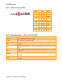
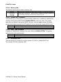
1.3 Document Amendment History
Revision Date By Comment
1st Aug. 2006 Jason Liu Initial Release

User’s Manual
ECM-3711 Series User’s Manual
11
1.4 Manual Objectives
This manual describes in detail the Evalue Technology ECM-3711 Single Board.
We have tried to include as much information as possible but we have not duplicated
information that is provided in the standard IBM Technical References, unless it proved to
be necessary to aid in the understanding of this board.
We strongly recommend that you study this manual carefully before attempting to interface
with ECM-3711 series or change the standard configurations. Whilst all the necessary
information is available in this manual we would recommend that unless you are confident,
you contact your supplier for guidance.
Please be aware that it is possible to create configurations within the CMOS RAM that
make booting impossible. If this should happen, clear the CMOS settings, (see the
description of the Jumper Settings for details).
If you have any suggestions or find any errors concerning this manual and want to inform
us of these, please contact our Customer Service department with the relevant details.

ECM-3711 Series
12 ECM-3711 Series User’s Manual
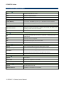
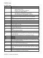
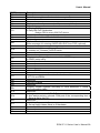
1.5 System Specifications
System
CPU
Onboard VIA Eden V4 1 GHz
BIOS
Award 512 KB Flash BIOS
System Chipset
VIA CN700/VT8251
I/O Chip
VIA VT1211
System Memory
One 200-pin SODIMM supports up to 1 GB DDR2 400/533 SDRAM
SSD
One CompactFlash Type I/II socket
Watchdog Timer
Reset: 1~255 min. and 1 sec./step
H/W Status Monitor
Monitoring system temperature, voltage, and cooling fan status. Auto
throttling control when CPU overheats.
Expansion
One Mini-PCI slot
I/O
MIO
2 x EIDE (Ultra DMA 100), 2 x SATA, 1 x RS-232, 1 x RS232/422/485, 1 x
K/B & Mouse
IrDA
115k bps, IrDA 1.0 compliant
DIO
16-bit General Purpose I/O for DI and DO
USB
4 x USB 2.0 ports
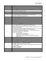
Display
Chipset
VIA ProSavage CN700 integrated 2D/3D gaphic engine
Display Memory
64 MB frame buffer using system memory
Resolution
CRT mode: 1600 x 1200 @ 24 bpp (60 Hz)
LCD/Simultaneous mode: 1600 x 1200 @ 24 bpp (60 Hz)
LVDS
Dual-channel 18/24-bit LVDS
Audio
Chipset
VIA VT8251
AC97 Codec
VIA VT1616 supports 5.1 CH Audio
Audio Interface
Mic in, Line in, CD Audio in, Line out
Ethernet
Chipset
Dual Realtek RTL8111B
Ethernet Interface
1000Base-T Fast Ethernet compatible

User’s Manual
ECM-3711 Series User’s Manual
13
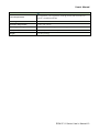
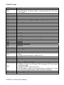
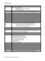
Mechanical & Environmental
Power Requirement
+5 V @ 4.63 A, +12 V @ 0.53 A, 5 Vsb @ 0.32 A (with VIA Eden V4 1
GHz & 1 GB DDR2 SDRAM)
Power Type
ATX
Operation Temperature
0~60°C (32~140°F)
Operating Humidity
0%~90% relative humidity, non-condensing
Size ( L x W )
45.7" x 4" (146 mm x 101 mm)
Weight
0.51 lbs (0.23 kg)

ECM-3711 Series
14 ECM-3711 Series User’s Manual
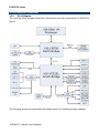
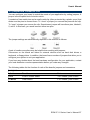
1.6 Architecture Overview
1.6.1 Block Diagram
The following block diagram shows the architecture and main components of ECM-3721
Series.
The following sections provide detail information about the functions provided onboard.

User’s Manual
ECM-3711 Series User’s Manual
15
1.6.2 VIA CN700 & VT8251
The CN700 implements a deep In-Order Queue to improve system performance for
multi-threaded software applications. DBI and V4 bus protocol are supported which
effectively reduce overall system power consumption. The AGP controller is AGP v3.5
compliant with up to 2.1GB/second data transfer rate. It supports pseudo-synchronous
AGP and CPU interface to maximize system performance. Deep read and write (256 bytes
each) FIFO are integrated for optimal bus utilization and minimum data transfer latency.
The CN700 supports 64-bit memory data bus access and the DDR DRAM interface allows
zero wait-state data transfer bursting between the DRAM and memory controller’s data
buffers. The different banks of DRAM can be composed of an arbitrary mixture of 64 / 128 /
256 / 512 / 1024 Mb SDRAM in x 8 or x16 configurations. The DRAM controller can run
either synchronous or pseudo-synchronous with the host CPU bus. The CN700 North
Bridge interfaces to the South Bridge through a high speed (up to 533 MB/sec) 8x 66 MHz
Data Transfer interconnect bus called V-Link interface. Deep pre-fetch and post-write
buffers are included to allow for concurrent CPU and V-Link operation. System Power
Management for sophisticated power management, the CN700 supports dynamic CKE
control to minimize DDR SDRAM power consumption during normal system state (S0). A
separate suspend power plane is implemented for the memory control logic for
Suspend-to-DRAM state. The CN700 graphics controller implements dynamic clock gating
for inactive functions to achieve maximum power saving. The system can be switched to
standby or suspend states to further reduce power consumption when idle. VESA DPMS
(Display Power Management Signaling) CRT power-down is supported. 3D Graphics
Engine Featuring an integrated 128-bit 3D graphics engine, the CN700 North Bridge
utilizes a single cycle architecture that provides high performance along with superior
image quality. Several new features enhance the 3D architecture, including single-pass
multitexturing, anisotropic filtering, and an 8-bit stencil buffer. The chip also offers the
industry’s only simultaneous usage of single-pass multitexturing and single-cycle trilinear
filtering – enabling stunning image quality without performance loss. Image quality is further
enhanced with true 32-bit color rendering throughout the 3D pipeline to produce more vivid
and realistic images. The advanced triangle setup engine provides realistic user
experiences in games and other interactive 3D applications. The 3D engine is optimized for
AGP texturing from system memory.

ECM-3711 Series
16 ECM-3711 Series User’s Manual
• 2D Graphics Engine
The CN700 North Bridge's advanced 128-bit 2D graphics engine delivers high-speed 2D
acceleration for productivity applications. The enhanced 2D architecture with direct access
frame buffer capability optimizes UMA performance and provides acceleration of all color
depths. MPEG Video Playback The CN700 North Bridge provides the ideal architecture for
high quality MPEG-2 based video applications. For MPEG playback, the integrated video
accelerator offloads the CPU by performing the motion compensation tasks, while its
enhanced scaling algorithm delivers incredible full-screen video playback. The CN700
provides three “Digital Video Port” interfaces: FPDP, GDVP1, and DVP0. The Flat Panel
Display Port (FPDP) implements a 24-bit / dual 12-bit interface which is designed to drive a
Flat Panel Display via an external LVDS transmitter chip. The CN700 can be connected to
the external LVDS transmitter chip in either 24-bit or dual-12-bit modes. A wide variety of
LCD panels are supported including VGA, SVGA, XGA, SXGA+ and up to UXGA-resolution
TFT color panels, in either SDR (1 pixel / clock) or DDR (2 pixels / clock) modes. Two 12-bit
“Display Port” interfaces are provided (through multiplexing with AGP interface) plus a
dedicated 12-bit display port interface. Multiplexing display functions with the AGP bus
allows embedded systems to support an external AGP connector for future performance
upgrade through the external graphics controller. It also allows add-in cards to be designed
with an AGP-compatible connector for implementing the display interface logic to reduce
cost in the base (CRT-only) configuration. In the value system configurations, the external
AGP upgrade capability is not normally required by the system, allowing all the AGP pins to
be used for implementing very flexible display functions.
Internally the CN700 North Bridge provides two separate display engines, so if two display
devices are connected, each can display completely different information at different
resolutions, pixel depths and refresh rates. If more than two display devices are connected,
the additional displays must have the same resolution, pixel depth and refresh rate as one
of the first two. The maximum display resolutions supported for one display device are
listed in the table below. If more than one display is implemented (i.e., if both display
engines are functioning at the same time), then available memory bandwidth may limit the
display resolutions supported on one or both displays. This will be dependent on many
factors including primarily clock rates and memory speeds (contact VIA for additional
information).

User’s Manual
ECM-3711 Series User’s Manual
17
The VT8251 interfaces to the companion North Bridge chip through the Ultra V-Link
interface with up to 1 GB/sec data transferrate. Two 1-Lane PCI Express ports are provided
for high-speed peripheral devices. The VT8251 allows combining the two 1-Lane PCI-E
ports into a 2-Lane port for peripheral that requires extra bandwidth. For standard 33 MHz
PCI devices, the VT8251 supports up to seven PCI master devices.
In addition, the VT251 integrates extensive peripheral controllers for modern,
state-of-the-art PC systems:
• Four-port Serial ATA / RAID Controller
The Serial ATA / RAID controller supports RAID Level 0, RAID Level 1, RAID Level 0+1
and JBOD, and complies with Serial ATA Specification Revision 1.0, and Serial ATA II
specification. The Serial ATA controller is configurable and can be configured to support
either 4 Serial ATA II master ports or 2/2 Serial ATA I master/slave ports with 3.0 Gbits/sec
and 1.5 Gbits/sec data transfer rates.
• Dual-channel Enhanced IDE Controller
In addition to standard PIO and DMA mode operation, the VT8251 also supports the
UltraDMA-133, 100, 66, and 33 standards, allows reliable data transfer rates up to 133
MB/sec. The IDE controller is SFF-8038i v1.0 and Microsoft Windows-family compliant.
• IEEE 802.3 compliant 10 / 100 Mbps Ethernet MAC with MII interface to external
PHYceiver
• Universal Serial Bus Controller with eight USB 2.0 ports
The VT8251 USB controller includes four USB 1.1 root hubs, a USB 2.0 root hub, and eight
USB 2.0 ports with integrated physical layer transceivers. Hot plug and isochronous
peripherals are supported. Support of legacy keyboard and mouse is implemented so that
legacy software could run transparently.
• Integrated AC97-link Controller
The AC-link controller can be used to attach an audio codec (AC), a modem codec (MC),
an audio modem codec (AMC) or a combination of ACs and a single MC.
• Full System Management Bus (SMBus) interface
• Keyboard controller with PS/2 mouse support
• Real Time Clock with 256 bytes extended CMOS
In addition to the standard ISA RTC functionality, the integrated RTC also includes the date
alarm, century field and other enhancements for compatibility with the ACPI standard.
• Notebook-class, sophisticated Power Management Unit compliant with ACPI and legacy
APM requirements
Multiple sleep states (POS, STR and STD) are supported with hardware automatic
wake-up. Additional functionality includes event monitoring, CPU clock throttling and stop,
PCI bus clock stop control, modular power, clock and leakage control, hardware-based and
software-based event handling, general purpose I/O, chip select and external SMI.

ECM-3711 Series
18 ECM-3711 Series User’s Manual
• Plug and Play functions with steerable PCI interrupts
The PnP function allows complete steerability of PCI interrupts and integrated peripheral
interrupts to system interrupt channel. One additional steerable interrupt channel is
provided to allow plug and play and re-configurability of on-board peripherals for Windows
family compliance.
The VT8251 also enhances the functionality of standard integrated peripherals. The
integrated interrupt controller supports both edge and level triggered interrupts channel by
channel. The integrated DMA controller supports type-F DMA in addition to standard ISA
DMA modes. Compliant with the PCI v2.3 specification, the VT8251 supports delayed
transactions so that slower internal ISA peripherals do not block the traffic of the PCI bus.
Special circuitry is built in to allow concurrent operation without causing deadlock in a
PCI-to-PCI bridge environment.
1.6.3 VIA VT1616 AC’97 Codec
VIA Technologies’ VT1616TM 18-bit audio codec conforms to the AC’97 2.2 and S/PDIF
output specifications. The VT1616 integrates Sample Rate Converters on all channels and
can be adjusted in 1Hz increments. There is a provision in hardware for down-mixing the 6
channels into stereo when only two end points are available. The analog mixer circuitry
integrates a stereo enhancement to provide a pleasing 3D surround
sound effect for stereo media. This codec is designed with aggressive power management
to achieve low power consumption. When used with a 3.3V analog supply, power
consumption is further reduced. The primary applications for this part are desktop and
portable personal computers multimedia subsystems. However, it is suitable for any
system requiring 6-channel audio output for home theater systems at competitive prices.
• AC’97 2.2 S/PDIF extension compliant codec
• 18-bit, 6 channel DAC outputs
• 1Hz resolution VSR on all channels
• Integrated IEC958 line driver for S/PDIF
• S/PDIF compressed digital or LPCM audio out
• Hardware downmixoption to 2 channels
• 3D stereo expansion for simulated surround
• 18-bit independent rate stereo ADC
• 4 stereo, 2 mono analog line-level inputs
• Second line-level output with volume control
• External Audio Amplifier Control
• Low Power consumption mode
• Exceeds MicrosoftR WHQL logo requirements
• 3.3V digital, 3.3 or 5V analog power supply
• 48-pin LQFP small footprint package

User’s Manual
ECM-3711 Series User’s Manual
19
1.6.4 VIA VT1636 LVDS Transmitter
• Support Single / Dual LVDS Transmitter Function
• Compatible with TIA/EIA-644 LVDS Standard
• Supports LVDS 18-bit and 24-bit Output
• Supports Dual Channel UXGA Panel Display
• Supports 2D Dither for 18-bit Panel
• Supports Option for 24-bit Color Mapping with Converntional (LSB) or
Non-Conventional (MSB) Format Output
• Supports DVO Input Mode with 25 to 165 MHz Input Clock
• Programmable Input Clock and Strobe Select
• Narrow bus Reduces Cable Size and Cost
• PLL equires No External Components
• Two-Wire Serial Communication
• Panel Protection and Power Down Sequencing
• Panel power Sequencing Control
• Supply Voltage 2.25-2.75V
• 64-pin LQFP Package (10 x 10 x 1.4mm)
1.6.5 VT1211 Super I/O
The VT1211 is a full function Super I/O chip that provides the most commonly used legacy
Super I/O functionality plus the latest Hardware monitor initiatives. The device uses an LPC
interface that complies with “LPC Interface Specification Revision 1.0”.
The VT1211 contains a Floppy Disk Controller, an IEEE-1284 Parallel Port interface, two
16C550-UART-based serial port interfaces, a VFIR (Very Fast IR) Controller, a game port
which supports 2 joysticks, a MIDI interface and a 4M Flash-ROM interface. The integrated
Hardware Monitor Controller controls the speed of 2 fans, monitors 2 fan tachometers and
has a Pentium II thermal diode and 5 Universal analog inputs for measuring voltage or
temperature (by connecting external thermistors). The VT1211 meets the “Microsoft PC98
& PC99 system design guide” requirements and is ACPI ready. The device requires a 48
MHz clock input and operates at 3.3V power supply.
The VT1211 consists of following logical devices. One high-performance 2.88MB floppy
disk controller, with digital data separator, which supports one 360K / 720K / 1.2M / 1.44M /
2.88M floppy disk drive; One multi-mode high-performance parallel port featuring support
for bi-directional Standard Parallel Port (SPP), Enhanced Parallel Port (EPP v1.7 and v1.9)
and IEEE1284 compliant Extended Capabilities Port (ECP) protocols; Two 16C550
standard compatible enhanced UARTs perform asynchronous communication; One VFIR
interface compliant with IrDA; One MIDI interface; One game port with built-in 558 and
buffer chips to support direct connect of 2 joysticks; One Hardware Monitor; and Seven
GPIO ports (56 GPIO pins).

ECM-3711 Series
20 ECM-3711 Series User’s Manual
A hardware monitor engine is built in to monitor system health. An enhanced 8 bit ADC is
built inside. This is exploited to simultaneously monitor 8 analog voltages or thermal inputs.
The thermal inputs can be defined independently as thermistor or PentiumTM II thermal
diode. Besides the ADC, the Hardware Monitor subsystem is also equipped with one
chassis-open detection and 5 VID inputs for PentiumTM II Vcore identification.
All logical devices can be individually enabled or disabled via software configuration
registers.
1.6.6 Ethernet
1.6.6.1 Realtek RTL8111B Ethernet Controller
The Realtek RTL8111 Gigabit Ethernet controller combines a triple-speed IEEE 802.3
compliant Media Access Controller (MAC) with a triple-speed Ethernet transceiver, PCI
Express bus controller, and embedded memory. With state-of-the-art DSP technology and
mixed-mode signal technology, it offers high-speed transmission over CAT 5 UTP cable or
CAT 3 UTP (10Mbps only) cable. Functions such as Crossover Detection &
Auto-Correction, polarity correction, adaptive equalization, cross-talk cancellation, echo
cancellation, timing recovery, and error correction are implemented to provide robust
transmission and reception capability at high speeds.
The device supports the PCI Express 1.0a bus interface for host communications with
power management and is compliant with the IEEE 802.3u specification for 10/100Mbps
Ethernet and the IEEE 802.3ab specification for 1000Mbps Ethernet. It also supports an
auxiliary power auto-detect function, and will auto-configure related bits of the PCI power
management registers in PCI configuration space.
Advanced Configuration Power management Interface (ACPI)--power management for
modern operating systems that are capable of Operating System-directed Power
Management (OSPM)—is also supported to achieve the most efficient power management
possible. PCI Message Signaled Interrupt (MSI) is also supported.
In addition to the ACPI feature, remote wake-up (including AMD Magic Packet™,
Re-LinkOk, and Microsoft® Wake-up frame) is supported in both ACPI and APM
(Advanced Power Management) environments. To support WOL from a deep power down
state (e.g., D3cold, i.e. main power is off and only auxiliary exists), the auxiliary power
source must be able to provide the needed power for the RTL8111.
The RTL8111 is fully compliant with Microsoft® NDIS5 (IP, TCP, UDP) Checksum and
Segmentation Task-offload features, and supports IEEE 802 IP Layer 2 priority encoding
and 802.1Q Virtual bridged Local Area Network (VLAN). The above features contribute to
lowering CPU utilization, especially benefiting performance when in operation on a network
server.
Page is loading ...
Page is loading ...
Page is loading ...
Page is loading ...
Page is loading ...
Page is loading ...
Page is loading ...
Page is loading ...
Page is loading ...
Page is loading ...
Page is loading ...
Page is loading ...
Page is loading ...
Page is loading ...
Page is loading ...
Page is loading ...
Page is loading ...
Page is loading ...
Page is loading ...
Page is loading ...
Page is loading ...
Page is loading ...
Page is loading ...
Page is loading ...
Page is loading ...
Page is loading ...
Page is loading ...
Page is loading ...
Page is loading ...
Page is loading ...
Page is loading ...
Page is loading ...
Page is loading ...
Page is loading ...
Page is loading ...
Page is loading ...
Page is loading ...
Page is loading ...
Page is loading ...
Page is loading ...
Page is loading ...
Page is loading ...
Page is loading ...
Page is loading ...
Page is loading ...
Page is loading ...
Page is loading ...
Page is loading ...
Page is loading ...
Page is loading ...
Page is loading ...
Page is loading ...
Page is loading ...
Page is loading ...
Page is loading ...
Page is loading ...
Page is loading ...
Page is loading ...
Page is loading ...
Page is loading ...
Page is loading ...
Page is loading ...
Page is loading ...
Page is loading ...
Page is loading ...
Page is loading ...
Page is loading ...
Page is loading ...
Page is loading ...
Page is loading ...
Page is loading ...
Page is loading ...
Page is loading ...
Page is loading ...
Page is loading ...
Page is loading ...
Page is loading ...
Page is loading ...
Page is loading ...
Page is loading ...
Page is loading ...
-
 1
1
-
 2
2
-
 3
3
-
 4
4
-
 5
5
-
 6
6
-
 7
7
-
 8
8
-
 9
9
-
 10
10
-
 11
11
-
 12
12
-
 13
13
-
 14
14
-
 15
15
-
 16
16
-
 17
17
-
 18
18
-
 19
19
-
 20
20
-
 21
21
-
 22
22
-
 23
23
-
 24
24
-
 25
25
-
 26
26
-
 27
27
-
 28
28
-
 29
29
-
 30
30
-
 31
31
-
 32
32
-
 33
33
-
 34
34
-
 35
35
-
 36
36
-
 37
37
-
 38
38
-
 39
39
-
 40
40
-
 41
41
-
 42
42
-
 43
43
-
 44
44
-
 45
45
-
 46
46
-
 47
47
-
 48
48
-
 49
49
-
 50
50
-
 51
51
-
 52
52
-
 53
53
-
 54
54
-
 55
55
-
 56
56
-
 57
57
-
 58
58
-
 59
59
-
 60
60
-
 61
61
-
 62
62
-
 63
63
-
 64
64
-
 65
65
-
 66
66
-
 67
67
-
 68
68
-
 69
69
-
 70
70
-
 71
71
-
 72
72
-
 73
73
-
 74
74
-
 75
75
-
 76
76
-
 77
77
-
 78
78
-
 79
79
-
 80
80
-
 81
81
-
 82
82
-
 83
83
-
 84
84
-
 85
85
-
 86
86
-
 87
87
-
 88
88
-
 89
89
-
 90
90
-
 91
91
-
 92
92
-
 93
93
-
 94
94
-
 95
95
-
 96
96
-
 97
97
-
 98
98
-
 99
99
-
 100
100
-
 101
101


Evalue Technology ECM-3711 Series User manual
- Type
- User manual
- This manual is also suitable for
Ask a question and I''ll find the answer in the document
Finding information in a document is now easier with AI
Related papers


Other documents
-
VIA Technologies vmpc vm7700 User manual
-
DeLOCK 66212 Datasheet
-
MiTAC 7521 PLUS/N User manual
-
Dahua SDZ4032-HNR-ZB User manual
-
JETWAY J7F4-F User manual
-
-
-
BCM IN810EP User manual
-
Avalue Technology ECM-KBLU User manual
-
Intel Intel Pentium M/Celeron M Processors Mini PC User manual