Kenwood KRF-V5050D User manual

Category
AV receivers
Type
User manual

This manual is also suitable for

Operations
Preparations
Additional Information
Remote Control
AUDIO VIDEO SURROUND RECEIVER
VR-506
VR-505
VR-517
KRF-V6050D
KRF-V5050D
KRF-V5550D
INSTRUCTION MANUAL
KENWOOD CORPORATION
B60-4942-10 03 MA (K, P, Y, M, X, I) 0009
PR
About the supplied remote control
Compared to standard remote controls, the remote control supplied with this receiver has several operation
modes. These modes enable the remote control to control other audio/video components. In order to
effectively use the remote control it is important to read the operating instructions and obtain a proper
understanding of the remote control and how to switch its operation modes (etc.).
Using the remote control without completely understanding its design and how to switch the operation modes
may result in incorrect operations.
This instruction manual is used to describe multiple models listed above.
Model availability and features (functions) may differ depending on the country and
sales area.
_4942-10 03 /01/EN 3/16/01, 10:15 AM1
2
Preparations
Units are designed for operation as follows.
U.S.A. and Canada ........................................... AC 120 V only
Australia ........................................................... AC 240 V only
Europe and U.K. ............................................... AC 230 V only
China and Russia ............................................ AC 220 V only
*Other countries ........... AC 110-120 / 220-240 V switchable
Note:
Our warranty does not cover damage caused by excessive line voltage
due to improper setting of the AC voltage selector switch.
* AC voltage selection
Move switch lever to
match your line voltage
with a small screw-
driver or other pointed
tool.
AC voltage selector switch
The AC voltage selector switch on the rear panel is set to the voltage that
prevails in the area to which the unit is shipped. Before connecting the
power cord to your AC outlet, make sure that the setting position of this
switch matches your line voltage. If not, it must be set to your voltage
in accordance with the following direction.
WARNING :
TO PREVENT FIRE OR ELECTRIC SHOCK, DO NOT
EXPOSE THIS APPLIANCE TO RAIN OR MOISTURE.
CAUTION: TO REDUCE THE RISK OF ELECTRIC SHOCK, DO NOT
REMOVE COVER (OR BACK). NO USER-SERVICEABLE PARTS IN-
SIDE, REFER SERVICING TO QUALIFIED SERVICE PERSONNEL.
THE LIGHTNING FLASH WITH ARROWHEAD SYMBOL,
WITHIN AN EQUILATERAL TRIANGLE, IS INTENDED TO ALERT
THE USER TO THE PRESENCE OF UNINSULATED “DAN-
GEROUS VOLTAGE” WITHIN THE PRODUCT’S ENCLOSURE
THAT MAY BE OF SUFFICIENT MAGNITUDE TO CONSTI-
TUTE A RISK OF ELECTRIC SHOCK TO PERSONS.
Safety precautions
THE EXCLAMATION POINT WITHIN AN EQUILATERAL TRI-
ANGLE IS INTENDED TO ALERT THE USER TO THE PRES-
ENCE OF IMPORTANT OPERATING AND MAINTENANCE
(SERVICING) INSTRUCTIONS IN THE LITERATURE ACCOM-
PANYING THE APPLIANCE.
Unpack the unit carefully and make sure that all accessories are put aside
so they will not be lost.
Examine the unit for any possibility of shipping damage. If your unit is
damaged or fails to operate, notify your dealer immediately. If your unit
was shipped to you directly, notify the shipping company without delay.
Only the consignee (the person or company receiving the unit) can file a
claim against the carrier for shipping damage.
We recommend that you retain the original carton and packing materials
for use should you transport or ship the unit in the future.
Keep this manual handy for future reference.
Before applying the power
Caution : Read this page carefully to ensure safe
operation.
Unpacking
*AC plug adaptor (1)
*Use to adapt the plug on the power
cord to the shape of the wall outlet.
(Accessory only for regions where use
is necessary.)
For VR-517 and KRF-V5550D
Batteries (R6/AA) (2)
Remote control unit (1)
RC-R0617
Remote control unit (1)
RC-R0511
Remote control unit (1)
RC-R0615
Batteries (R6/AA) (2)
Accessories
FM indoor antenna (1)
AM loop antenna (1)
For VR-505 and KRF-V5050D
Batteries (R6/AA) (2)
Microcomputer malfunction
If operation is not possible or an erroneous display appears, even though
all connections have been made properly, reset the microcomputer
referring to “In case of difficulty”. ·
Maintenance of the unit
When the front panel or case becomes dirty, wipe with a soft, dry
cloth. Do not use thinner, benzine, alcohol, etc. for these agents may
cause discoloration.
In regard to contact cleaner
Do not use contact cleaners because it could cause a malfunction.
Be specially careful not to use contact cleaners containing oil, for
they may deform the plastic component.
L
VIDEO 1
R
A
LC
LR
LR
B
PLAY INREC OUTPLAY IN
MONITOR
OUT
VIDEO 1
DVD
R
AC 110V -
120V
AC 220V -
240V
75µs
AM 10kHz
FM 100kHz
50µs
AM 9kHz
FM 50kHz
DE-
EMPHASIS
CHANNEL
SPACE
CAUTION
RISK OF ELECTRIC SHOCK
DO NOT OPEN
For VR-506 and KRF-V6050D
_4942/02-09/EN 3/16/01, 10:16 AM2
3
OperationsOperations
Preparations
Remote Control
Additional Information
Before applying the power ................... 2
Safety precautions .............................................. 2
Unpacking .......................................................... 2
How to use this manual ...................................... 4
Special features .................................................. 4
Names and functions of parts ................ 5
Remote control unit (RC-R0615)
(VR-506/KRF-V6050D) ....................................... 6
Remote control unit (RC-R0511)
(VR-505/KRF-V5050D) ....................................... 7
Remote control unit (RC-R0617)
(VR-517/KRF-V5550D) ....................................... 8
Setting up the system ......................... 9
Connecting audio components ......................... 10
Connecting video components ......................... 11
Connecting a DVD player (6-channel input) ...... 12
Digital connections ........................................... 13
Connecting to the AV AUX jacks
(VR-506/517/KRF-V6050D only)....................... 14
Connecting the antennas .................................. 14
Connecting the system control ......................... 15
Connecting the speakers .................................. 16
Preparing the remote control ............................ 18
Preparing for surround sound ............... 19
Speaker settings ............................................... 19
Normal playback .............................. 20
Preparing for playback ...................................... 20
Listening to a source component ..................... 21
Adjusting the sound .......................................... 21
Recording ...................................... 22
Recording audio (analog sources) .................... 22
Recording video ................................................ 23
Recording audio (digital sources) ...................... 23
Listening to radio broadcasts ............... 23
Tuning radio stations ........................................ 23
Presetting radio stations manually .................... 24
Receiving preset stations .................................. 24
Receiving preset stations in order (P.CALL) ...... 24
Ambience effects .............................. 25
Surround modes ............................................... 25
Surround play ................................................... 27
DVD 6-channel playback
(VR-506/517/KRF-V6050D/V5050D) ................ 28
Convenient functions ........................................ 28
Basic remote control operations for other
components(For VR-506/517/KRF-V6050D/
V5550D) ........................................ 30
Registering setup codes for other
components ...................................................... 30
Operating other components ............................ 30
Setup code chart .............................................. 31
DVD player operation keys
(For VR-505/KRF-V5050D) ............................... 32
Cassette deck, CD player & MD recorder
operations (For VR-505/KRF-V5050D) ............. 33
Cassette deck, CD player & MD recorder
operations (For VR-506/517/KRF-V6050D/
V5550D) ............................................................ 34
Other components’ operations (For VR-506/517/
KRF-V6050D/V5550D) ..................................... 36
Contents
Caution : Read the pages marked carefully to ensure
safe operation.
Preparations
Operations
Remote Control
Operations
Before applying the power
In case of difficulty ........................... 39
Specifications ................................. 41
Additional
Information
For the U.S.A.
FCC WARNING
This equipment may generate or use radio frequency energy. Changes
or modifications to this equipment may cause harmful interference
unless the modifications are expressly approved in the instruction
manual. The user could lose the authority to operate this equipment if an
unauthorized change or modification is made.
NOTE:
This equipment has been tested and found to comply with the limits for
a Class B digital device, pursuant to Part 15 of the FCC Rules. These limits
are designed to provide reasonable protection against harmful interfer-
ence in a residential installation. This equipment may cause harmful
interference to radio communications, if it is not installed and used in
accordance with the instructions. However, there is no guarantee that
interference will not occur in a particular installation. If this equipment does
cause harmful interference to radio or television reception, which can be
determined by turning the equipment off and on, the user is encouraged
to try to correct the interference by one or more of the following measures:
– – Reorient or relocate the receiving antenna.
– – Increase the separation between the equipment and receiver.
Connect the equipment into an outlet on a circuit different from that
to which the receiver is connected.
Consult the dealer or an experienced radio / TV technician for help.
Note to CATV system installer:
This reminder is provided to call the CATV system installer's attention to
Article 820-40 of the NEC that provides guidelines for proper grounding
and, in particular, specifies that the cable ground shall be connected to
the grounding system of the building, as close to the point of cable entry
as practical.
For the U.S.A.
As an ENERGY STAR
®
Partner, Kenwood Corpora-
tion has determined that this product meets the
ENERGY STAR
®
guidelines for energy efficiency.
This product can save energy. Saving energy reduces air pollution and
lowers utility bills.
_4942/02-09/EN 3/16/01, 10:16 AM3
4
Preparations
Special features
True home theater sound
This receiver incorporates a wide variety of surround modes to bring you
maximum enjoyment from your video software. Select a surround mode
according to your equipment or the software you are going to play and
enjoy!
Dolby Pro Logic & Dolby 3 Stereo
This surround system reproduces theater-like surround sound from
video software marked
.
The PRO LOGIC mode uses the built-in adaptive matrix circuit to steer
the Left, Center, Right and Surround channel audio signals.
The 3 STEREO mode will redirect the Surround signal to the front left
and right speakers when only the front and center speakers are used.
Dolby Digital
The DOLBY DIGITAL mode lets you enjoy full digital surround from
software processed in the Dolby Digital format. Dolby Digital provides
up to 5.1 channels of independent digital audio for better sound quality
and more powerful presence than conventional Dolby Surround.
DTS
DTS (Digital Theater System) is a 5.1 channel digital audio format that
provides five full-spectrum channels and one low-frequency (subwoofer)
channel for unprecedented clarity, optimum channel separation and a
(wide) dynamic range.
In the DTS mode, the 5.1 channel digital input from a DTS CD, LD or
DVD disc (carrying the “DTS” marking) can be played in Digital Sur-
round.
Important:
When a DTS disc is played on a CD, LD or DVD player, noise may be
output from the analog output. It is recommended that you connect the
digital output of the player to the digital input of this unit.
DSP surround modes
The DSP (Digital Signal Processor) used for this receiver incorporates
a variety of high quality adjustable sound fields, like “ARENA”, “JAZZ
CLUB”, THEATER”, STADIUM” and “DISCO”. It is compatible with
almost any kind of program source.
DVD 6-channel input
(For VR-506/517/KRF-V6050D/V5050D only)
If you own a DVD player equipped with 6-channel output, this receiver
allows you to obtain the full surround sound impact of DVD source
material featuring multi-channel encoding. Since the source signals are
digital and each channel is input independently, the resulting ambience
is far superior to what can be achieved with conventional surround
sound systems.
Universal IR (InfraRed) remote control
(Except for VR-505/KRF-V5050D)
In addition to the basic receiver, the remote control supplied with this
receiver can also operate almost all of your remote controllable audio and
video components. Just follow the simple setup procedure to register the
components you have connected.
How to use this manual
This manual is divided into four sections, Preparations, Operations,
Remote Control, and Additional Information.
Preparations
Shows you how to connect your audio and video components to the
receiver and prepare the surround processor.
We will guide you to make setting up your system as easy as possible.
However, since this receiver works with all of your audio and video
components, connecting the system can be fairly complex.
Operations
Shows you how to operate the various functions available on the receiver.
Remote Control
(For VR-506/517/KRF-V6050D/V5550D only)
Shows you how to operate other components using the remote control,
as well as a detailed explanation of all remote control operations. Once
you have registered your components with the proper setup codes, you’ll
be able to operate both this receiver and your other AV components (TV,
VCR, DVD player, CD player, etc.) using the remote control supplied with
this receiver.
Additional Information
Shows you additional information such as “In case of difficulty” (trouble-
shooting) and “Specifications”.
Before applying the power
This manual covers the VR-506, VR-505, VR-517, KRF-V6050D, KRF-
V5050D and KRF-V5550D. Items such as functions, number of jacks, and
remote control details somewhat differ between these models. To confirm
the functions available on the model you have purchased, refer to the table
below.
Model name
Remote
Terminal
Control
Speaker out
Front input
VR-506 RC-R0615 2 systems Equipped
KRF-V6050D (A, B)
VR-505 RC-R0511 1 system Not equipped
KRF-V5050D
VR-517 RC-R0617 1 system Equipped
KRF-V5550D (except KRF-
V5550D)
Memory back up function
Please note that the following items will be deleted from the unit's
memory if the power cord is disconnected from the AC outlet for
approximately 2 days.
Power mode.
Input selector settings.
Device preset.
Picture output.
Speaker ON/OFF
Volume level.
BASS, TREBLE, INPUT level.
Subwoofer ON/OFF.
Dimmer level.
Monitor ON/OFF.
MD/TAPE settings.
6ch/2ch input setting.
Listen mode setting.
Speaker settings.
Input mode setting.
Midnight mode setting.
Broadcast band.
Frequency setting.
Preset stations.
Tuning mode.
CINEMA EQ.
Source Direct.
_4942/02-09/EN 3/16/01, 10:16 AM4
5
Preparations
A SPEAKERS B
STANDBY
POWER
LISTEN MODE
SOUND
MULTI CONTROL
SOURCE DIRECT
AUTO/CINEMA EQ.BAND MEMORY
INPUT SELECTOR
VOLUME CONTROL
UPDOWN
DSP MODE
DTS
INPUT MODESET UP
S-VIDEO V L – AUDIO – R
AV AUX
DIMMER MONITOR
PHONES
ON/STANDBY
ON OFF
DOLBY
DIGITAL
TI.VOL
TP
RDS EON PTY
TA NEWS
FM
AM
MHz
kHz
PRO LOGIC
3 STEREO
DOWNMIX
DIGITAL
S.DIRECT
MONITOR
MEMO
ST.
TUNED
AUTO SOUND
AUTO
SP
LFE SW
C
AB
MUTE
S SRSL
RL
STANDBY
POWER
ON/STANDBY
SPEAKER MUTE
DSP
CLIP
Display
Speaker selection indicators
Input channel indicators
Output channel indicators
Band indicators
AUTO indicator
MEMO indicator
ST. indicator
TUNED indicator
3 STEREO indicator
STEREO indicator
Names and functions of parts
Frequency display,
Input display,
Preset channel display,
Surround mode display
Speaker indicator
PRO LOGIC
indicator
S.DIRECT indicator
MONITOR indicator
DOWNMIX indicator
For VR-506/
505/517
MUTE indicator
AUTO SOUND indicator
DIGITAL indicator
For VR-506/517/
KRF-V6050D
1 POWER key (
(For KRF-V6050D/V5050D/V5550D)
Use to turn the main power ON/OFF.
2 ON/STANDBY (
) key (
(For KRF-V6050D/V5050D/V5550D)
Use to switch the power ON/STANDBY when
the POWER is turned ON.
STANDBY indicator
2 POWER ( ) key (
(For VR-506/505/517)
Use to turn the power ON/STANDBY.
STANDBY indicator
3 MULTI CONTROL keys (
Use to control a variety of settings.
4 SET UP key (
Use to select the speakers' settings etc.
5 Surround indicators
DTS indicator
Lights when the receiver is in the DTS mode.
DOLBY DIGITAL indicator
Lights when the receiver is in the Dolby Digital
mode.
DSP MODE indicator
Lights up when the receiver is in DSP mode.
6 INPUT MODE key 9
Use to switch between the digital and analog
inputs.
7 DIMMER key £ª
Use to adjust the brightness of the display.
Use to select the REC MODE.
8 MONITOR key
Use to monitor the source that is connected to
the MONITOR jack.
9 VOLUME CONTROL knob ¡
0 PHONES jack
Use for headphone listening.
! SPEAKERS A/B keys )
(For VR-506/KRF-V6050D)
Use to turn the A/B speakers ON/OFF.
! SPEAKER key )
(For VR-505/517/KRF-V5050D/V5550D)
Use to turn the speaker ON/OFF.
MUTE key
(For VR-505/517/KRF-V5050D/V5550D)
Use to temporarily mute the sound.
@ SOUND key
Use to adjust the sound quality and ambience
effects.
For VR-505/517/
KRF-V5050D/V5550D
DSP indicator
# BAND key £
Use to select the broadcast band.
$ AUTO/CINEMA EQ. key £
Use to select the auto tuning mode.
Use to switch the status of CINEMA EQ.
% LISTEN MODE key
Use to select the listening mode.
^ MEMORY key ¢
Use to store radio stations in the preset memory.
& SOURCE DIRECT key
Use to pass the source material direct to the
amplifier.
* INPUT SELECTOR knob ¡
Use to select the input sources.
( AV AUX (S VIDEO, V, AUDIO L/R) jacks
(For VR-506/517/KRF-V6050D) $
Standby mode
When standby indicator is lit, this receiver is in standby mode and consumes a small amount of curent for back-up. This system can be switched on using
remote controls.
CLIP indicator
_4942/02-09/EN 3/16/01, 10:16 AM5
6
Preparations
1
B.BOOST
DISC SKIP
DVD
PHONO CD/DVD
TUNER
MD/TAPE
VIDEO1 VIDEO2
CINE.EQ
AV AUX
23
POWER
POWER
TV
VCR
DVD
CABLE
DSS
RETURN
OSDMENU
P.CALL
TUNING
MUTE VOLUME
A/B+100
TV SEL.
RECEIVER
AUTO
INPUT SEL.TITLE
DISC SEL.
DVD
CHANNEL
ENTER
BAND
P.CALL
456
789
0 +10
LSTN M.
SET UP SOUND
MULTI CONTROL
1
7
!
8
9
0
@
2
4
3
5
6
#
$
¡
*
)
^
&
(
%
7 B.BOOST key ¡
Use to select the maximum adjustment set-
ting for the low frequency range.
RECEIVER key
Use to return to the operation of the receiver.
8 DISC SKIP key
If CD is selected as the input source, this key
functions as the multi-CD player disc skip key.
A/B key
If TAPE is selected as the input source, this
(A and B) of a double cassette deck.
+100 key
Use to select the disc number with the multi-
CD player.
9 TITLE key
Use to operate other components.
0 TV SEL. key
Use to operate other components.
! INPUT SELECTOR keys (DVD, PHONO,
CD/DVD, TUNER, MD/TAPE, VIDEO1,
VIDEO2, AV AUX) ¡
Use to select the input sources.
4 DVD ¢ keys
When in DVD player operations, these keys
function as skip keys.
@ MUTE key
Use to temporarily mute the sound.
# POWER (
) key *
Use to turn the receiver on and off.
$ POWER key (TV, VCR, DVD, DSS,
CABLE)
Use to turn the other components on and off.
% ENTER key
Use to select the input sources.
2 key
If tape is selected as the input source, this
key functions as the play key for side B of the
cassette (the side facing away from the front
of the deck).
^ BAND key
Use to select the broadcast band.
6 key
If CD is selected as the input source, this key
functions as the play/pause key.
If MD or TAPE is selected as the input
source, this key functions as the play key.
& AUTO key £
Use to select the auto tuning mode.
7 key
If CD, MD or TAPE is selected as the input
source, this key functions as the stop key.
* 8 key
Use to operate other components.
( INPUT SEL. key
Use to operate other components.
) CHANNEL %¥fi key
Use to select the channel.
¡ CINE.EQ key
Use to switch the status of CINEMA EQ.
DISC SEL. key
Use to operate other components.
VOLUME keys ¡
Use to adjust the receiver volume.
1 Numeric keys
Provide functions identical to those of the
original remote control supplied with the
component you are controlling.
2 LSTN M. key
Use to select the listening mode.
RETURN key
Use to operate other components.
3 SET UP key (
Use to select the speakers' settings etc.
MENU key
Use to operate other components.
4 SOUND key ¡
Use to adjust the sound quality and ambi-
ence effects.
OSD key
Use to operate other components.
5 MULTI CONTROL keys (
Use to control a variety of settings.
Use to operate other components.
P.CALL 4/¢ keys ¢
If tuner is selected as the input source, these
keys function as P.CALL keys.
4/¢ keys
If CD or MD is selected as the input source,
these keys function as skip keys.
6 TUNING 1/¡ keys
Use to operate the tuner or selected com-
ponent.
If CD, MD or TAPE is selected as the input
source, these keys function as search keys.
Names and functions of parts
Remote control unit (RC-R0615) (VR-506/KRF-V6050D)
If the name of a function is different on
the receiver and on the remote control,
the name of the remote control key in
this manual is indicated in parentheses.
This remote control unit can be used not only for Kenwood products but also for other non-Kenwood products
by setting the appropriate maker setup codes.
_4942/02-09/EN 3/16/01, 10:17 AM6
7
Preparations
1
DISC SKIP
BASS BOOST
AUTO
PHONO/AUX
CD/DVD
DVD
TUNER
MD/TAPE
VIDEO1 VIDEO2
23
POWER
DVD
POWER
RECEIVER
MENU
P.CALL
TUNING
MUTE
VOLUME
A/B+100
DVD
ENTER
BAND
P.CALL
MULTI CONTROL
456
789
0 +10
SET UP
OSD
SOUND
RETURN
TITLE
LISTEN MODE
1
6
8
7
9
3
2
4
5
0
!
@
#
$
)
^
%
*
DISC SEL.
CINE.EQ
(
&
Names and functions of parts
Remote control unit (RC-R0511) (VR-505/KRF-V5050D)
7 DISC SKIP key
If CD is selected as the input source, this key
functions as the multi-CD player disc skip key.
A/B key
If TAPE is selected as the input source, this
(A and B) of a double cassette deck.
+100 key
Use to select the disc number with the multi-
CD player.
8 INPUT SELECTOR keys (DVD, PHONO/
AUX, CD/DVD, TUNER, MD/TAPE,
VIDEO1, VIDEO2) ¡
Use to select the input sources.
4 DVD ¢ keys
When in DVD player operations, these keys
function as skip keys.
9 MUTE key
Use to temporarily mute the sound.
0 POWER (
) key *
Use to turn the receiver on and off.
! DVD POWER key
Used to operate DVD player.
For details, refer to the instruction manual of
your DVD player. (Press the DVD POWER
key for more than 2 seconds.)
@ RECEIVER key
Use to return to the operation of the receiver.
# TITLE key
Use to operate other components.
1 Numeric keys ¢
If CD or MD is selected as the input source,
these keys function as numeric keys. If tuner
is selected as the input source, these keys
are used to call up station presets.
2 SET UP key (
Use to select the speakers' settings etc.
MENU key
Use to operate other components.
3 SOUND key ¡
Use to adjust the sound quality and ambi-
ence effects.
OSD key
Use to operate other components.
4 MULTI CONTROL keys (
Use to control a variety of settings.
P.CALL 4/¢ keys ¢
If tuner is selected as the input source, these
keys function as P.CALL keys.
4/¢ keys
If CD or MD is selected as the input source,
these keys function as skip keys.
5 TUNING 1/¡ keys
If tuner is selected as the input source, these
keys function as tuning keys.
If CD, MD or TAPE is selected as the input
source, these keys function as search keys.
6 BASS BOOST key ¡
Use to select the maximum adjustment set-
ting for the low frequency range.
$ LISTEN MODE key
Use to select the listening mode.
RETURN key
Use to operate other components.
% ENTER key
Use to operate other components.
2 key
If tape is selected as the input source, this key
functions as the play key for side B of the
cassette (the side facing away from the front of
the deck).
^ BAND key £
Use to select the broadcast band.
6 key
If CD is selected as the input source, this key
functions as the play/pause key.
If MD or TAPE is selected as the input source,
this key functions as the play key.
& 8 key
Use to operate other components.
* AUTO key £
Use to select the auto tuning mode.
7 key
If CD, MD or TAPE is selected as the input source,
this key functions as the stop key.
( CINE.EQ key
Use to switch the status of CINEMA EQ.
DISC SEL. key
Use to operate other components.
) VOLUME keys ¡
Use to adjust the receiver volume.
_4942/02-09/EN 3/16/01, 10:17 AM7
8
Preparations
1
B.BOOST
DISC SKIP
DVD
AUX CD/DVD
TUNER
MD/TAPE
VIDEO1 VIDEO2 CINE.EQ AV AUX
23
POWER
POWER
TV
VCR
DVD
CABLE
DSS
RETURN
OSDMENU
P.CALL
TUNING
MUTE VOLUME
A/B+100
TV SEL.
RECEIVER
AUTO
INPUT SEL.TITLE
DISC SEL.
DVD
CHANNEL
ENTER
BAND
P.CALL
456
789
0 +10
LSTN M.
SET UP SOUND
MULTI CONTROL
1
7
!
8
9
0
@
2
4
3
5
6
#
$
¡
*
)
^
&
(
%
7 B.BOOST key ¡
Use to select the maximum adjustment set-
ting for the low frequency range.
RECEIVER key
Use to return to the operation of the receiver.
8 DISC SKIP key
If CD is selected as the input source, this key
functions as the multi-CD player disc skip key.
A/B key
If TAPE is selected as the input source, this
(A and B) of a double cassette deck.
+100 key
Use to select the disc number with the multi-
CD player.
9 TITLE key
Use to operate other components.
0 TV SEL. key
Use to operate other components.
! INPUT SELECTOR keys (DVD, AUX, CD/
DVD, TUNER, MD/TAPE, VIDEO1,
VIDEO2, AV AUX) ¡
Use to select the input sources.
4 DVD ¢ keys
When in DVD player operations, these keys
function as skip keys.
@ MUTE key
Use to temporarily mute the sound.
# POWER (
) key *
Use to turn the receiver on and off.
$ POWER key (TV, VCR, DVD, DSS,
CABLE)
Use to turn the other components on and off.
% ENTER key
Use to operate other components.
2 key
If tape is selected as the input source, this
key functions as the play key for side B of the
cassette (the side facing away from the front
of the deck).
^ BAND key £
Use to select the broadcast band.
6 key
If CD is selected as the input source, this key
functions as the play/pause key.
If MD or TAPE is selected as the input
source, this key functions as the play key.
& AUTO key £
Use to select the auto tuning mode.
7 key
If CD, MD or TAPE is selected as the input
source, this key functions as the stop key.
* 8 key
Use to operate other components.
( INPUT SEL. key
Use to operate other components.
) CHANNEL %¥fi key
Use to select the channel.
¡ CINE.EQ key
Use to switch the status of CINEMA EQ.
DISC SEL. key
Use to operate other components.
VOLUME keys ¡
Use to adjust the receiver volume.
1 Numeric keys
Provide functions identical to those of the
original remote control supplied with the
component you are controlling.
2 LSTN M. key
Use to select the listening mode.
RETURN key
Use to operate other components.
3 SET UP key (
Use to select the speakers' settings etc.
MENU key
Use to operate other components.
4 SOUND key ¡
Use to adjust the sound quality and ambi-
ence effects.
OSD key
Use to operate other components.
5 MULTI CONTROL keys (
Use to control a variety of settings.
Use to operate other components.
P.CALL 4/¢ keys ¢
If tuner is selected as the input source, these
keys function as P.CALL keys.
4/¢ keys
If CD or MD is selected as the input source,
these keys function as skip keys.
6 TUNING 1/¡ keys
Use to operate the tuner or selected com-
ponent.
If CD, MD or TAPE is selected as the input
source, these keys function as search keys.
Names and functions of parts
Remote control unit (RC-R0617) (VR-517/KRF-V5550D)
If the name of a function is different on
the receiver and on the remote control,
the name of the remote control key in
this manual is indicated in parentheses.
This remote control unit can be used not only for Kenwood products but also for other non-Kenwood products
by setting the appropriate maker setup codes.
_4942/02-09/EN 3/16/01, 10:17 AM8
9
Preparations
Make connections as shown in the following pages.
When connecting the related system components, be sure
to also refer to the instruction manuals supplied with the
components you are connecting.
Do not connect the power cord to a wall outlet until all
connections are completed.
Notes
1. Be sure to insert all connection cords securely. If their connections are
imperfect, the sound may not be produced or noise may interfere.
2. Be sure to remove the power cord from the AC outlet before plugging or
unplugging any connection cords. Plugging/unplugging connection cords
without disconnecting the power cord can cause malfunctions and may
damage the unit.
3. Do not connect power cords from components whose power consump-
tion is larger than what is indicated on the AC outlet at the rear of this unit.
Setting up the system
DTS Digital Surround™ is a discrete 5.1 channel digital audio format
available on CD, LD, and DVD software which consequently cannot be
decoded and played back inside most CD, LD, or DVD players. For this
reason, when DTS-encoded software is played back through the analog
outputs of the CD, LD, or DVD player, excessive noise will be exhibited.
To avoid possible damage to the audio system, proper precautions
should be taken by the consumer if the analog outputs are connected
directly to an amplification system. To enjoy DTS Digital Surround™
playback, an external 5.1 channel DTS Digital Surround™ decoder
system must be connected to the digital output (S/P DIF, AES/EBU, or
TosLink) of the CD, LD or DVD player.
DTS disclaimer clause
VIDEO 2/MONITOR jacks
The receiver’s VIDEO 2/MONITOR jacks can be used in two different
ways. Make the appropriate setting for the component connected to the
jack when the receiver is turned on.
Use as a VIDEO 2 jack
You can connect a video deck or the like to these jacks and perform
video playback and recording. The initial factory setting is “VIDEO 2”.
Use as a MONITOR jack
You can connect a cassette deck or the like to these jacks and make use
of the deck’s monitoring function during recording. Alternately, you can
connect a graphic equalizer to these jacks to apply compensation to the
music signal.
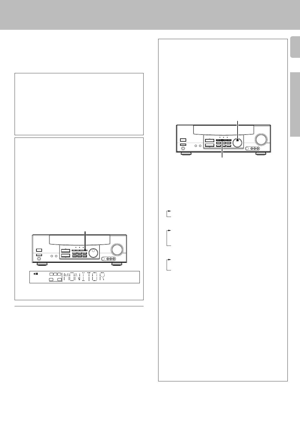
To use the VIDEO 2/MONITOR jacks as a MONITOR jack, hold down
the MONITOR key of the main unit for more than two seconds so that
the display below appears.
To switch the setting back to “VIDEO 2,” once again hold down the
MONITOR key for more than two seconds.
MONITOR
Analog connections
Audio connections are made using RCA pin cords. These cables transfer
stereo audio signal in an “analog” form. This means the audio signal
corresponds to the actual audio of two channels. These cables usually have
2 plugs each end, one red for the right channel and one white for the left
channel. These cables are usually packed together with the source unit, or
are available at your local electronics retailer.
TUNED
AUTO
FM
MHz
AM
kHz
PRO LOGIC
3
DOWN MIX
DIGITAL
S.DIRECT
DSP
AUTO SOUND
LFE
C
S
TI.VOLB
CLIP MUTE
RDS EON PTY
TP TA NEWS
STEREO
ST.
MEMO
SW
RL
SP A
MONITOR
Input mode settings
CD/DVD, VIDEO2 and DVD/6ch or DVD (VR-505/KRF-V5550D only)
inputs each include jacks for digital audio input and analog audio input.
You must select beforehand which type of input is to be used for each
connected component.
The initial factory settings for audio signal playback (CD/DVD,DVD/
6ch or DVD (VR-505/KRF-V5550D only)) and (VIDEO2) are digital
and analog respectively.
To use the analog audio input for playback instead (if, for example, you
have connected a VCR to the VIDEO2 input), you must set the input
mode for the corresponding input to the analog mode.
After completing connections and turning on the receiver, follow the
steps below.
1 Use the INPUT SELECTOR knob to select CD/DVD, VIDEO2,
DVD/6ch or DVD (VR-505/KRF-V5550D only).
2 Press the INPUT MODE key.
Each press switches the setting as follows:
In DTS play mode
1 D-AUTO (digital input, auto sound)
2 D-MANUAL (digital input, manual sound)
In DVD/6ch or DVD play mode
1 D-AUTO (digital input, auto sound)
2 D-MANUAL (digital input, manual sound)
3 6ch INPT (DVD/6ch input)(except for VR-505/KRF-V5550D)
4 ANALOG (analog input, manual sound)
In modes other than DTS or DVD play mode
1 D-AUTO (digital input, auto sound)
2 D-MANUAL (digital input, manual sound)
3 ANALOG (analog input, manual sound)
Digital input:
Select this setting to play digital signals from a DVD, CD, or LD player.
Analog input:
Select this setting to play analog signals from a cassette deck, VCR,
or record player.
Auto sound:
In the auto sound mode (AUTO SOUND indicator lights), the receiver
selects the listening mode automatically during playback to match the
type of input signal (Dolby Digital, PCM, DTS ) and the speaker setting.
The initial factory setting is auto sound on.
To keep the receiver set to the currently selected listening mode, use
the INPUT MODE key to select “D-MANUAL” (manual sound).
However, even when this setting is selected, there may be cases in
which the listening mode is selected automatically to match a Dolby
Digital source signal depending on the combination of listening mode
and source signal.
If the INPUT MODE key is pressed quickly, sound may not be
produced.
INPUT SELECTOR
INPUT MODE
_4942/02-09/EN 3/16/01, 10:17 AM9
10
Preparations
Connecting audio components
When you connect the audio cord of the video component to the VIDEO 2/MONITOR jacks, connect the video cord (yellow RCA pin cords)
of the connected component to the VIDEO 2 IN jack.
Record player
Setting up the system
VIDEO 1
R
A
LC
LR
LR
B
PLAY INREC OUTPLAY IN
MONITOR
OUT
VIDEO 1
DVD
R
VIDEO2/MONITOR
PLAY INPLAY IN
REC OUT
AUDIO
L
R
MD/TAPE
CD/DVD
PHONO
REC OUT
L
R
AUX
GND
75µs
AM 10kHz
FM 100kHz
50µs
AM 9kHz
FM 50kHz
DE-
EMPHASIS
CHANNEL
SPACE
To AC wall outlet
Cassette deck or
MD recorder
CD or DVD player
IN
OUT
SYSTEM CONTROL
jacks %
Shape of AC outlets
U.S.A. and Canada
Other countries
Video component,
3 head cassette deck, or
Graphic equalizer
IN
OUT
OUT
OUT
Australia
(For VR-505/517/KRF-V5550D)
Moving coil (MC) cartridge
record player cannot be used
directly from the receiver unit. It
can only be used when another
equalizer amplifier is connected.
_4942/10-19/EN 3/16/01, 3:04 PM10
11
Preparations
L
VIDEO 1
R
A
LC
LR
LR
B
PLAY INREC OUTPLAY IN
MONITOR
OUT
VIDEO 1
DVD
R
75µs
AM 10kHz
FM 100kHz
50µs
AM 9kHz
FM 50kHz
DE-
EMPHASIS
CHANNEL
SPACE
VIDEO 2 IN
VIDEO
MONITOR
OUT
VIDEO 1
OUT
VIDEO 1 IN
IN
CD/DVD
DVD
VIDEO 2/MONITOR
AUDIO
VIDEO 1
PLAY IN
REC OUT PLAY INREC OUT
CD / DVD
MD / TAPE
PLAY IN
REC OUT
DVD
S VIDEO
VIDEO 1 VIDEO 1
MONITOR
OUT
PLAY IN REC OUT PLAY IN
Connecting video components
IN
Video inputs and
outputs
(Yellow RCA pin cords)
Setting up the system
Video deck
Monitor TV
OUT
Audio inputs
and outputs
A video component with digital audio outputs should be connected to the VIDEO2 jacks.
VIDEO
IN
DVD player or LD player
IN
OUT
OUT
OUT
S Video jacks
(VR-506/517/KRF-V6050D)
Video inputs
(Yellow RCA pin cords)
About the S VIDEO
jacks
Use the S VIDEO jacks to
make connections to
video components with S
VIDEO IN/OUT jacks.
÷ If you use the S VIDEO
jacks to connect your video
playback components, be
sure to use the S VIDEO
jacks when connecting
your monitor and video
recording components.
S VIDEO
IN
_4942/10-19/EN 3/16/01, 3:04 PM11
12
Preparations
VIDEO 3VIDEO 2VIDEO 1
R
A
LC
LR
LR
B
PLAY INPLAY INPLAY INREC OUTPLAY IN
MONITOR
OUT
VIDEO 1
DVD
R
DVD
PLAY IN
FRONT
CENTER DVD
SURROUND
VIDEO 2/MONITOR
COAXIAL
SUB
WOOFER
DVD/6CH. INPUT
VIDEO 2 IN
VIDEO
MONITOR
OUT
VIDEO 1
OUT
VIDEO 1 IN
CD/DVD
DVD
IN
L
R
75µs
AM 10kHz
FM 100kHz
50µs
AM 9kHz
FM 50kHz
DE-
EMPHASIS
CHANNEL
SPACE
Connecting a DVD player (6-channel input)
FRONT
OUT L/R
S VIDEO
OUT
COAXIAL
DIGITAL
OUT
(AUDIO)
DVD player
S VIDEO cord
SURROUND
OUT L/R
VIDEO OUT
(Yellow RCA
pin cord)
CENTER OUT
SUBWOOFER OUT
If you have connected a DVD player to the receiver with digital connection, be sure to read the “Input
mode settings” section carefully. 9
CAUTION (Except for U.S.A. and Canada)
Be sure to adhere followings. Or proper ventilation will be blocked causing damage or fire hazard.
Do not place any objects impairing heat radiation onto the top of unit.
Leave a space around the unit (from the largest outside dimension including projection) equal or greater than, shown below.
Top panel : 50 cm Side panel : 10 cm Back panel : 10 cm
CAUTION (For U.S.A. and Canada)
Be sure to adhere followings. Or proper ventilation will be blocked causing damage or fire hazard.
Do not place any objects impairing heat radiation onto the top of unit.
To switch the speakers off , press the MUTE key.
(Except for VR-505/KRF-V5550D)
Setting up the system
_4942/10-19/EN 3/16/01, 3:04 PM12
13
Preparations
L
VIDEO 1
R
A
LC
LR
LR
B
PLAY INREC OUTPLAY IN
MONITOR
OUT
VIDEO 1
DVD
R
75µs
AM 10kHz
FM 100kHz
50µs
AM 9kHz
FM 50kHz
DE-
EMPHASIS
CHANNEL
SPACE
DVD
VIDEO 2/MONITOR
COAXIAL
CD/DVD
OPTICAL
DIGITAL IN
Digital connections
COAXIAL
DIGITAL
OUT
(AUDIO)
Connect the video signal and analog
audio signals to the VIDEO 2 jacks.
(See “Connecting video components”.)
!
DOLBY DIGITAL RF
OUT (AUDIO)
COAXIAL DIGITAL OUT (AUDIO)
LD player
PCM OUT
Component with a DTS, Dolby
Digital, or PCM COAXIAL
DIGITAL OUT
Setting up the system
The digital in jacks can accept DTS, Dolby Digital, or PCM signals. Connect components capable
of outputting DTS, Dolby Digital, or standard PCM (CD) format digital signals.
If you have connected any digital components to the receiver, be sure to read the “Input mode
settings” section carefully. 9
To connect an LD player with a DIGITAL RF OUT, connect the LD player to the KENWOOD RF digital demodulator (DEM-9991D).
Next, connect the DIGITAL OUT jacks of the demodulator to the DIGITAL IN jacks of the receiver.
Connect the video signal and analog audio signals to the VIDEO 2/MONITOR jacks. (See “Connecting video components”.)
RF digital
demodulator
(DEM-9991D)
(sold separately)
CD player
OPTICAL DIGITAL OUT (AUDIO)
Optical fiber
cable
_4942/10-19/EN 3/16/01, 3:04 PM13
14
Preparations
S VIDEO V L — AUDIO — R
AV AUX
The AV AUX jacks are convenient for connection of video components
such as a camcorder or a video game.
Connecting to the AV AUX jacks
(VR-506/517/KRF-V6050D only)
S VIDEO OUT
Camcorder, other VCR,
video game, digital camera,
or portable MD player
S VIDEO cord
VIDEO OUT
AUDIO OUT
To select the source connected to the AV AUX jacks, select AV
AUX by using the INPUT SELECTOR knob. ¡
When you connect the audio source such as the MD player, you
do not need to connect the video cable.
When you connect the unit and the component with the S
VIDEO cord, you can get better picture quality.
Connecting the antennas
AM antenna terminal connections
1 Push lever. 2 Insert cord.
AM loop antenna
The supplied loop antenna is for use indoors. Place it as far as possible from
the receiver, TV set, speaker cords and power cord, and adjust the direction
for best reception.
3 Release lever.
FM indoor antenna
The supplied indoor antenna is for temporary use only. For stable signal
reception we recommend using an outdoor antenna. Disconnect the indoor
antenna when you connect one outdoors.
FM outdoor antenna
Lead the 75 coaxial cable connected to the FM outdoor antenna into the
room and connect it to the FM 75 terminal.
FM antenna terminal connections
Insert cord.
VIDEO 1
R
A
LC
LR
LR
B
PLAY INREC OUTPLAY IN
MONITOR
OUT
VIDEO 1
DVD
R
FM
75
GND
ANTENNA
AM
75µs
AM 10kHz
FM 100kHz
50µs
AM 9kHz
FM 50kHz
DE-
EMPHASIS
CHANNEL
SPACE
AM loop antenna
FM indoor antenna
FM outdoor antenna
Use an antenna
adaptor
(Commercially
available)
Attach to the stand.
Setting up the system
_4942/10-19/EN 3/16/01, 3:04 PM14
15
Preparations
Connecting the system control
Connecting system control cords after connecting a KENWOOD
audio component system lets you take advantage of convenient
system control operations.
This unit is compatible only with the [SL-16] mode. The system
control operation is not available if the unit is connected in the
[XS8], [XS], or [XR] connection mode.
If your component has the mode select switch, set the connected
components to the [SL16] mode.
[
SL16]
[
SL16] [XS] [XS8] [XR]
[
SL16] [XS] [XS8]
[XS]
SYSTEM
CONTROL
cord
Receiver
Cassette deck
or MD recorder
CD player
Record player
In order to take advantage of the system control operations, the
components must be connected to the correct jacks. To use a CD
player it must be connected to the CD jacks. To use a cassette deck
(or MD recorder) it must be connected to the MD/TAPE jacks. When
using more than one CD player (etc.) only the one connected to the
specified jacks may be connected for system control.
Some CD players and cassette decks are not compatible with the
[SL16] system control mode. Do not make system connections with
equipment that is not [SL16] compatible.
Some MD players are not system control compatible. You cannot
make system control connections to this kind of equipment.
Notes
1. [SL16] equipment cannot be combined with [XR], [XS], and [XS8]
equipment for system operations. If your equipment consists of this
kind of combination, please do not connect any system control cords.
Even without system control cords, normal operations can be carried
out without effecting performance.
2. Do not connect system control cords to any components other than
those specified by KENWOOD. It may cause a malfunction and
damage your equipment.
3. Be sure the system control plugs are inserted all the way in to the
system control terminals.
EXAMPLE: [SL16] mode connections
The underlined portion represents the setting of the system control
mode.
Do not connect a system control cord to a cassette deck connected
to the VIDEO2/MONITOR jacks.
SYSTEM CONTROL
cord
SYSTEM
CONTROL
• You may connect the system control cord to either the left or right jack.
SYSTEM CONTROL OPERATIONS
Remote Control
Lets you operate this unit with the system remote supplied with the
receiver.
Automatic Operation
When you start playback from a source component, the input selector
on this unit switches to that component automatically.
Synchronized Recording
Lets you synchronize recording with the start of playback when record-
ing from CD, MD or analog discs.
Registering setup codes for KENWOOD audio components
(VR-506/517/KRF-V6050D/V5550D)
• If you own remote controllable KENWOOD audio components that are
not compatible with system control, registering the setup code en-
ables you to control those components using the remote control
supplied with this unit (without connecting system control cords). To
register setup codes for your remote controllable KENWOOD audio
components, see “Registering setup codes for other components”.
º
Setting up the system
_4942/10-19/EN 3/16/01, 3:04 PM15
16
Preparations
Setting up the system
Connecting the speakers
1 Strip coating.
2 Loosen.
3 Insert. 4 Secure.
Never short circuit the + and – speaker cords.
If the left and right speakers are connected inversely or the speaker
cords are connected with reversed polarity, the sound will be unnatu-
ral with ambiguous acoustic imaging. Be sure to connect the speak-
ers correctly.
1 Secure.
2 Insert.
Connection of banana plugs (For U.S.A. and Canada)
Sound will not be heard if the speaker terminal is not fully secured.
Speaker impedance
After confirming the speaker impedance indications printed on the rear
panel of the receiver, connect speakers with matching impedance
ratings. Using speakers with a rated impedance other than that indi-
cated on the rear panel of the receiver could result in malfunctions or
damage to the speakers or receiver.
1 Strip coating.
2 Push the lever.
3 Insert the cord. 4 Return the lever.
_4942/10-19/EN 3/16/01, 3:04 PM16
17
Preparations
L
VIDEO 1
R
A
LC
LR
LR
B
PLAY INREC OUTPLAY IN
MONITOR
OUT
VIDEO 1
DVD
R
75µs
AM 10kHz
FM 100kHz
50µs
AM 9kHz
FM 50kHz
DE-
EMPHASIS
CHANNEL
SPACE
FRONT SPEAKERS CENTER SPEAKER
FRONT SPEAKERS
SURROUND SPEAKERS
RED BLUE GREEN
GRAYORANGE
+
-
+
-
FRONT
SPEAKERS
CENTER
SPEAKER
RED BLUE GREEN
+
-
+
-
SURROUND
SPEAKERS
(8 16)
SUB WOOFER
SPEAKER
(8 16)
GRAYORANGEBROWN
+
+
SURROUND SPEAKERS
(8 16)
GRAYORANGE
SW
FRONT SPEAKERS CENTER SPEAKER
RED BLUE GREEN
SUB WOOFER
PRE OUT
Setting up the system
Right
Front Speakers A
Right
Left
(Be sure to connect both
surround speakers)
Center
Speaker
Surround Speakers
Powered
subwoofer
Connecting the speakers
The VR-505/517/KRF-V5050D/V5550D are equipped with one-touch
speaker terminals.They are arranged in the same manner as the speaker
terminals of the VR-506/KRF-V6050D. Refer to the instructions on
making connections to the VR-506/KRF-V6050D when making con-
nections to the VR-505/517/KRF-V5050D/V5550D.
VR-517/KRF-V5550D
VR-505/KRF-V5050D
VR-506/KRF-V6050D
VR-517/KRF-V5550D
VR-505/KRF-V5050D
Use the FRONT SPEAKERS
B terminals if you want to
connect a second front
speaker system (for VR-506/
KRF-V6050D).
VR-506/KRF-V6050D
Left
(Except
VR-517/
KRF-V5550D)
_4942/10-19/EN 3/16/01, 3:04 PM17
18
Preparations
Speaker placement
Subwoofer
Front speakers : Place to the front left and right of the listening position.
Front speakers are required for all surround modes.
Center speaker : Place front and center. This speaker stabilizes the
sound image and helps recreate sound motion. Be sure to connect a
center speaker when using the Dolby 3 Stereo mode.
Surround speakers : Place to the direct left and right, or slightly
behind, the listening position at even heights, approximately 1 meter
above the ears of the listeners. These speakers recreate sound motion
and atmosphere. Required for surround playback.
Subwoofer : Reproduces powerful deep bass sounds.
Front
speaker
Center speaker
Listening
position
Surround
speaker
• Although the ideal surround system consists of all the speakers listed
above, if you don't have a center speaker or a subwoofer, you can
divide those signals between the available speakers in the speaker
settings steps to obtain the best possible surround reproduction from
the speakers you have available. (
Setting up the system
Channel space switching
(Except for the USA, Canada, UK, Europe, and Australia)
The space between radio channels has been set to the one that prevails
in the area to which the system is shipped. However, if the current
channel space setting does not match the setting in the area where the
system is to be used, for instance when you move from area 1 or area
2 shown in the following table or vice versa, proper reception of AM/FM
broadcasts cannot be expected. In this case, change the channel space
setting in accordance with your area by referring to the following table.
CHANNEL
Space Frequency
Area
1
2
USA, Canada and South
American countries
Other countries
FM: 100 kHz
AM: 10 kHz
FM: 50 kHz
AM: 9 kHz
Move switch lever to match your area with a small screwdriver or
other pointed tool.
Preparing the remote control
Notes
1. The supplied batteries may have shorter lives than ordinary batteries due
to use during operation checks.
2. When the remote-controllable distance gets shorter than before, replace
both batteries with new ones.
3. Placing the remote sensor in direct sunlight, or in direct light from a high
frequency fluorescent lamp may cause a malfunction.
In such a case, change the location of the system installation to prevent
malfunction.
6 m
• When pressing more than one remote control key successively, press
the keys securely by leaving an interval of 1 second or more between
keys.
Operation
When the STANDBY indicator is lit, the power turns ON when you press
the POWER key on the remote control. When the power comes ON,
press the key you want to operate.
VIDEO 1
R
A
PLAY INREC OUTPLAY IN
MONITOR
OUT
VIDEO 1
DVD
R
75µs
AM 10kHz
FM 100kHz
50µs
AM 9kHz
FM 50kHz
DE-
EMPHASIS
CHANNEL
SPACE
DE-
EMPHASIS
CHANNEL
SPACE
Loading the batteries
3 Close the cover.
2 Insert the batteries.
1 Remove the cover.
1
2
Insert two AA-size (R6) batteries as indicated by the polarity markings.
Operating range
(Approx.)
Remote sensor
Infrared ray system
_4942/10-19/EN 3/16/01, 3:05 PM18
19
Preparations
From your usual listening position, adjust the volume levels. The volume
levels from each speaker should be the same.
1 Use the MULTI CONTROL keys to adjust the volume of the test
tone output from the speaker channel to be adjusted.
The test tone is heard from the speakers in the following
sequence for 2 seconds each:
L = C = R = SR = SL = SW
If you change the volume level settings for the speakers while listening
to music, the settings referred to on this page are also changed.
• If the speaker setting selects are changed, the speaker level settings
are reset.
2 Press the SET UP key.
• The test tone is turned off. The receiver enters the mode for inputting
the distance to the speakers.
Preparing for surround sound
Speaker settings
If you have selected other than LRG as the center speaker
setting,
1 SURR ON: Surround speaker setting mode to the receiver
is ON.
2 SURR OFF: Surround speaker setting mode to the receiver
is OFF.
9 Press the SET UP key again to accept the setting.
Turn on the power to this receiver by pressing POWER
or ON/STANDBY key(s).
Select a speaker system.
1
2
3
1 Press the SET UP key such that the subwoofer setting
indication (SUBW ON) appears.
2 Use the MULTI CONTROL keys to select the appropriate
subwoofer setting.
1 SUBW ON: Subwoofer setting mode to the receiver is ON.
2 SUBW OFF:
Subwoofer setting mode to the receiver is OFF.
The initial setting is “SUBW ON”.
When the setting “SUBW OFF” is selected, the front speakers are
automatically set to “FRNT LRG” and the procedure skips to step 5.
When subwoofer output sound is required, select “FRNT NML”.
3 Press the SET UP key to accept the setting.
The front speakers setting indication (FRNT) appears.
4 Use the MULTI CONTROL keys to select the appropriate front
speakers setting.
1 FRNT NML (normal): Average size front speakers are
connected to the receiver.
2 FRNT LRG (large): Large front speakers are con-
nected to the receiver.
For “FRNT LRG” selection, no sound will be heard from SUBW even
when it is set to ON. However, if you select CINEMA EQ. when
subwoofer is selected, you will be able to hear sound from the
subwoofer.
When in STEREO mode, the sound goes directly to front speaker.
5 Press the SET UP key to accept the setting.
The center speaker setting indication (CNTR) appears.
Adjust the speaker volume.
To enable you to obtain optimum enjoyment from the receiver’s listening
modes, make sure to complete the speaker settings (subwoofer, front,
center, and surround speakers) as described below.
Continued to next page
If you have selected NML as the front speakers setting,
1 CNTR ON: Center speaker setting mode to the receiver is
ON.
2 CNTR OFF: Center speaker setting mode to the receiver is
OFF.
7 Press the SET UP key again to accept the setting.
The surround speaker setting indication (SURR) appears.
8 Use the MULTI CONTROL keys to select the appropriate surround
speaker setting.
If you selected LRG as the center speaker setting,
1 SURR LRG (large): Large surround speakers are con-
nected to the receiver.
2 SURR NML (normal): Average size surround speakers are
connected to the receiver.
3 SURR OFF: Surround speaker setting mode to the
receiver is OFF.
FM
AM
MHz
kHz
PRO LOGIC
3
DOWN MIX
DIGITAL
S.DIRECT
MONITOR
DSP
MEMO
ST.
TUNED
AUTO SOUND
AUTO
LFE
C
S
RSLS
TI.VOLB
CLIP MUTE
RDS EON PTY
TP TA NEWS
SW
RL
SP A
STEREO
FM
AM
MHz
kHz
PRO LOGIC
3
DOWN MIX
DIGITAL
S.DIRECT
MONITOR
DSP
MEMO
ST.
TUNED
AUTO SOUND
AUTO
LFE
C
S
RSLS
TI.VOLB
CLIP MUTE
RDS EON PTY
TP TA NEWS
SW
RL
SP A
STEREO
6 Use the MULTI CONTROL keys to select the appropriate center
speaker setting.
If you selected LRG as the front speakers setting,
1 CNTR LRG (large): A large center speaker is connected to
the receiver.
2 CNTR NML (normal): An average size center speaker is con-
nected to the receiver.
3 CNTR OFF: Center speaker setting mode to the
receiver is OFF.
The receiver enters the speaker volume level adjustment mode.
• In steps 3 and 4, indications appear only for the selected channels
of the speakers that require adjusting.
MULTI CONTROL
(KRF-V6050D/
V5050D/
V5550D)
SET UP
POWER
ON/STANDBY
RC-R0511
SET UP
RC-R0615/R0617
MULTI
CONTROL
The channel indication blinks while the test tone is being output.
STEREO
R
FM
AM
MHz
kHz
PRO LOGIC
3
DOWN MIX
DIGITAL
S.DIRECT
MONITOR
DSP
MEMO
ST.
TUNED
AUTO SOUND
AUTO
LFE
C
S
RSLS
TI.VOLB
CLIP MUTE
RDS EON PTY
TP TA NEWS
L
SP A
=
_4942/10-19/EN 3/16/01, 3:05 PM19
20
Operations
Preparing for surround sound
Input level adjustment (analog sources only)
If the input level of an analog source signal is too high, adjust the input
level. The CLIP indicator will blink to indicate the source signal.
1 Use the INPUT SELECTOR knob to select the source which
input level you want to adjust.
You can store a separate input level for each input source. If the
MONITOR function is ON, you can store an input level for when
MONITOR is on independently of the input levels for the input
sources.
2 Press the SOUND key repeatedly until the “INPUT” indication
appears.
3 Use the MULTI CONTROL keys to adjust the input level.
• The adjustment mode is displayed for approximately eight seconds.
The input level may be adjusted to any one of three settings: 0dB,
-3dB, and -6dB. (The initial setting is 0dB.)
4 Press the SOUND key again to return to the input indication.
Preparing for playback
Normal playback
Some preparatory steps are needed before starting playback.
Turning on the receiver
1 Turn on the power to the related components.
2 Turn on the power to this receiver by pressing POWER (and ON/
STANDBY) key(s).
Selecting MD/TAPE
Select the source name corresponding to the component connected to
the MD/TAPE jacks. The initial factory setting is “TAPE”. To change the
source to “MD,” follow the steps below:
1 Use the INPUT SELECTOR knob to select “TAPE”.
2 Hold down the AUTO/CINEMA EQ. key for more than 2 seconds.
The source indication changes to “MD”.
To return to the original indication, repeat procedure 2.
A ON : Sound from the speakers connected to the SPEAKERS A
terminals on the rear panel.
B ON : Sound from the speakers connected to the SPEAKERS B
terminals on the rear panel.
A+B ON : Sound from both the speakers connected to the
SPEAKERS A and B terminals on the rear panel.
A+B OFF : No sound from the speakers. Use this setting when listening
with headphones for stereo sound in all playback modes.
5 Setup is complete when the input indication reappears.
Display when all speakers have been selected.
The speakers you have selected should appear on the display.
Confirm that all the speakers have been correctly selected.
4
The speaker indicator to be adjusted blinks.
Indication in feet Indication in meters
1 Measure the distance from the listening position to each of the
speakers.
Jot down the distance to each of the speakers.
Distance to front speakers: ____ feet____ meters
Distance to center speaker: ____ feet____ meters
Distance to surround speakers: ____ feet____ meters
2 Use the MULTI CONTROL keys to select the distance to the
front speakers.
• The allowable setting range is 1 to 30 feet (0.3 to 9.0 m), adjustable
in 1 foot (0.3 m) increments.
3 Press the SET UP key to accept the settings.
4 Repeat steps 2 and 3 to input the distance for each of the
speakers.
Operations
Input the distance to the speakers.
LFE
C
S
RSLS
TI.VOLB
CLIP MUTE
RDS EON PTY
TP TA NEWS
L
SP A
R
SW
SW
STEREO
FM
AM
MHz
kHz
PRO LOGIC
3
DOWN MIX
DIGITAL
S.DIRECT
MONITOR
DSP
MEMO
ST.
TUNED
AUTO SOUND
AUTO
LFE
C
S
RSLS
TI.VOLB
CLIP MUTE
RDS EON PTY
TP TA NEWS
L
SP A
R
STEREO
STEREO
FM
AM
MHz
kHz
PRO LOGIC
3
DOWN MIX
DIGITAL
S.DIRECT
MONITOR
DSP
MEMO
ST.
TUNED
AUTO SOUND
AUTO
LFE
C
S
RSLS
TI.VOLB
CLIP MUTE
RDS EON PTY
TP TA NEWS
L
SP A
R
STEREO
SW
LFE
C
S
RSLS
TI.VOL
CLIP MUTE
RDS EON PTY
TP TA NEWS
L
SP A
R
SW
B
Selecting the speaker system (VR-506/KRF-V6050D only)
Press the SPEAKERS A or B key to select the speaker system to
be used.
LFE
C
S
RSLS
TI.VOL
CLIP MUTE
RDS EON PTY
TP TA NEWS
L
SP A
R
SW
B
The speaker indicator lights.
VR-505/517/KRF-V5050D/
V5550D
VR-506/KRF-V6050D
The indicator for the speakers
you want to use should be lit.
• Selecting “6ch INPT” by pressing the INPUT MODE key, whereby “DVD/
6ch” is the input source will cause SPEAKER A to be selected automati-
cally.
On the VR-505/517/KRF-V5050D/V5550D, press the SPEAKER key to
switch the speakers on and off.
KRF-V6050D/
V5050D/
V5550D
AUTO/CINEMA EQ.
INPUT MODE
POWER
ON/STANDBY
INPUT SELECTOR
SPEAKERS A/B
(SPEAKER/MUTE)
RDS
TP
CLIP
Selecting the input mode
If you have selected a component connected to the CD/DVD, DVD/6ch,
DVD (VR-505/KRF-V5550D only) or VIDEO2/MONITOR jacks, make
sure that the input mode setting is correct for the type of audio signal to
be used. 9
_4942/20-22/EN 3/16/01, 3:07 PM20
  • Page 1 1
  • Page 2 2
  • Page 3 3
  • Page 4 4
  • Page 5 5
  • Page 6 6
  • Page 7 7
  • Page 8 8
  • Page 9 9
  • Page 10 10
  • Page 11 11
  • Page 12 12
  • Page 13 13
  • Page 14 14
  • Page 15 15
  • Page 16 16
  • Page 17 17
  • Page 18 18
  • Page 19 19
  • Page 20 20
  • Page 21 21
  • Page 22 22
  • Page 23 23
  • Page 24 24
  • Page 25 25
  • Page 26 26
  • Page 27 27
  • Page 28 28
  • Page 29 29
  • Page 30 30
  • Page 31 31
  • Page 32 32
  • Page 33 33
  • Page 34 34
  • Page 35 35
  • Page 36 36
  • Page 37 37
  • Page 38 38
  • Page 39 39
  • Page 40 40
  • Page 41 41
  • Page 42 42
  • Page 43 43
  • Page 44 44

Kenwood KRF-V5050D User manual

Category
AV receivers
Type
User manual
This manual is also suitable for

Ask a question and I''ll find the answer in the document

Finding information in a document is now easier with AI