Motorola DCT700 User manual

Category
TV set-top boxes
Type
User manual

This manual is also suitable for

Installation Manual
DCT700
Digital Consumer Terminal
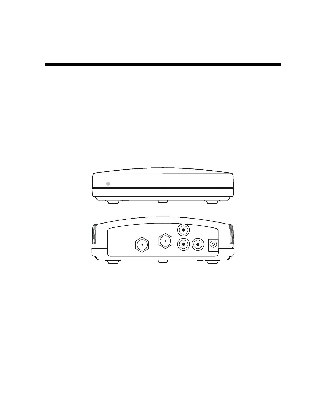
Graphical symbols and supplement warning marking locations on the bottom of the appliance.
This symbol indicates that dangerous voltage levels are present within the equipment. These voltages are not insulated
and may be of sufficient strength to cause serious bodily injury when touched. The symbol may also appear on
schematics.
This symbol calls attention to a critical procedure, or means refer to the instruction manual for opening or service
information. Only qualified service personnel are to install or service the equipment. The symbol may also appear in
text and on schematics.
WARNING:
TO PREVENT FIRE OR SHOCK HAZARD, DO NOT EXPOSE THIS APPLIANCE TO RAIN OR MOISTURE.
CAUTION:
TO PREVENT ELECTRICAL SHOCK, DO NOT USE THIS PLUG WITH AN EXTENSION CORD, RECEPTACLE, OR OTHER OUTLET
UNLESS THE BLADES CAN BE FULLY INSERTED TO PREVENT BLADE EXPOSURE.
FCC Compliance: Federal Communications Commission Radio and Television Interface Statement for a Class ‘B’ Device
This equipment has been tested and found to comply with the limits for a Class B digital device, pursuant to part 15 of the FCC Rules. These
limits are designed to provide reasonable protection against harmful interference in the residential installation. This equipment generates, uses
and can radiate radio frequency energy and, if not installed and used in accordance with the instructions, may cause harmful interference to
radio communications. However, there is no guarantee that interference will not occur in a particular installation.
If the equipment does cause harmful interference to radio or television reception, which can be determined by turning the equipment off and on,
the user is encouraged to try to correct the interference by one of the following measures:
! Reorient or relocate the receiver antenna
! Increase the separation between the equipment and the affected receiver
! Connect the equipment into an outlet or on a circuit different from that to which the receiver is connected
! Consult the dealer or experienced radio/TV technician for help
! Ensure that the cover plate for the security card is secured and tight
Changes or modification not expressly approved by the party responsible for compliance could void the user’s authority to operate the equipment.
Declaration of Conformity: According to 47 CFR, Parts 2 and 15 for Class B Personal Computers and Peripherals; and/or CPU Boards and
Power Supplies used with Class B Personal Computers, Motorola, Inc., 6450 Sequence Drive, San Diego, CA 92121, 1-800-225-9446, declares
under sole responsibility that the product identifies with 47 CFR Part 2 and 15 of the FCC Rules as a Class B digital device. Each product
marketed is identical to the representative unit tested and founded to be compliant with the standards. Records maintained continue to reflect the
equipment being produced can be expected to be within the variation accepted, due to quantity production and testing on a statistical basis as
required by 47 CFR 2.909. Operation is subject to the following condition: This device must accept any interference received, including
interference that may cause undesired operation. The above named party is responsible for ensuring that the equipment complies with the
standards of 47 CFR, Paragraphs 15.107 to 15.109
Repairs: If repair is necessary, call the Motorola Repair Facility at 1-800-227-0450 for a Return for Service Authorization (RSA) number before
sending the unit. The RSA number must be prominently displayed on all equipment cartons. Pack the unit securely; enclose a note describing
the exact problem, and a copy of the invoice that verifies the warranty status. Ship the unit PRE-PAID to the following address:
Motorola, Inc.
Attn: RSA #___________
c/o Rudolph Miles and Sons
2500 Courage Boulevard
Brownsville, TX 78521
NOTE TO CATV SYSTEM INSTALLER: This reminder is provided to call CATV system installer’s attention to Article 820-40 of the NEC that
provides guidelines for proper grounding and, in particular, specifies that the cable ground shall be connected to the grounding system of the
building, as close as possible to the point of cable entry as practical.
Copyright © 2003 by Motorola, Inc.
All rights reserved. No part of this publication may be reproduced in any form or by any means or used to make any derivative work (such as
translation, transformation or adaptation) without written permission from Motorola, Inc.
Motorola reserves the right to revise this publication and to make changes in content from time to time without obligation on the part of Motorola
to provide notification of such revision or change. Motorola provides this guide without warranty of any kind, either implied or expressed,
including, but not limited to, the implied warranties of merchantability and fitness for a particular purpose. Motorola may make improvements or
changes in the product(s) described in this manual at any time.
STARVUE, MOTOROLA, and the Stylized M Logo are registered in the US Patent & Trademark Office. Manufactured under license from Dolby
Laboratories. "Dolby" and the double-D symbol are registered trademarks of Dolby Laboratories. All other product or service names are the
property of their respective owners.
DCT700 Installation Manual
Contents
Section 1
Introduction
Standard Features.................................................................................................................................................................. 1-2
Standard Interfaces ................................................................................................................................................................1-2
Using This Manual..................................................................................................................................................................1-2
Related Documentation .......................................................................................................................................................... 1-2
Document Conventions.......................................................................................................................................................... 1-3
If You Need Help.....................................................................................................................................................................1-3
Calling for Repairs..................................................................................................................................................................1-3
Section 2
Overview
Remote Control.......................................................................................................................................................................2-2
Installing Batteries in the Remote Control..................................................................................................................... 2-4
Section 3
Installation
Before You Begin....................................................................................................................................................................3-1
Installing the DCT700 .............................................................................................................................................................3-1
Standard Cabling Diagram .....................................................................................................................................................3-2
Standard VCR Cabling Diagram.............................................................................................................................................3-3
Composite Baseband Cabling Diagrams ...............................................................................................................................3-4
Stereo Cabling Diagrams (Baseband) .................................................................................................................................... 3-6
Operational Check..................................................................................................................................................................3-8
Selecting the OOB Frequency........................................................................................................................................ 3-8
Set-top Cold Initialization .......................................................................................................................................................3-9
ii Contents
DCT700 Installation Manual
Section 4
Troubleshooting
Appendix A
Specifications
Appendix B
Diagnostics
Using Diagnostics.................................................................................................................................................................. B-2
d 01: General Status............................................................................................................................................................... B-3
Error Codes ................................................................................................................................................................... B-5
d 02: Out-of-Band (OOB) Status ............................................................................................................................................B-6
Selecting the OOB Frequency....................................................................................................................................... B-7
d 03: In-band Status............................................................................................................................................................... B-8
d 04: Audio/Video Status ....................................................................................................................................................... B-9
d 05: Unit Address ............................................................................................................................................................... B-10
d 06: Firmware Version........................................................................................................................................................ B-11
d 07: Current Channel Status .............................................................................................................................................. B-11
d 08: Renewable Security .................................................................................................................................................... B-14
d 09: Upstream Modem (STARVUE II Diagnostics) ............................................................................................................. B-15
d 10: Application (APP) Code Modules ............................................................................................................................... B-15
d 11: Memory Status............................................................................................................................................................ B-16
d 12: Interactive Info ............................................................................................................................................................ B-17
d 13: MAC Frequency Table................................................................................................................................................. B-18
d 14: Control Channels........................................................................................................................................................ B-18
d 15: Message Types ........................................................................................................................................................... B-19
d 16: In-Band Program Association Table (PAT)................................................................................................................. B-19
d 17 In-Band Program Map Table (PMT).............................................................................................................................. B-19
d 18: Task Status ................................................................................................................................................................. B-19
d 19: USB Diagnostics......................................................................................................................................................... B-20
d 20 In-Band Multicast Address Filter ................................................................................................................................. B-20
d 21: Keyboard / LED Diagnostics....................................................................................................................................... B-20
Abbreviations and Acronyms
Contents iii
DCT700 Installation Manual
Figures
Figure 1-1 DCT700 set-top front and rear views....................................................................................................................1-1
Figure 2-1 Front panel ............................................................................................................................................................ 2-1
Figure 2-2 Rear panel.............................................................................................................................................................2-1
Figure 2-3 Motorola DRC450 Universal Remote Control.......................................................................................................2-2
Figure 2-4 Back view of DRC450 remote control .................................................................................................................. 2-4
Figure 3-1 Connecting the DCT700 to a TV using RF connectors ........................................................................................3-2
Figure 3-2 Standard VCR cabling.......................................................................................................................................... 3-3
Figure 3-3 Standard baseband cabling ................................................................................................................................. 3-4
Figure 3-4 Baseband audio and video connections to a VCR and TV ..................................................................................3-5
Figure 3-5 Audio on the VCR................................................................................................................................................. 3-6
Figure 3-6 Audio on VCR/Audio output on TV ......................................................................................................................3-7
Tables
Table 2-1 Rear panel features................................................................................................................................................2-1
Table 2-2 DRC450 remote control keys.................................................................................................................................2-3
Table 3-1 Operational check procedures ..............................................................................................................................3-8
Table 4-1 Troubleshooting guidelines...................................................................................................................................4-1
DCT700 Installation Manual
Section 1
Introduction
The Motorola DCT700 is an interactive digital consumer terminal that enables cable operators
to cost-effectively deploy an all-digital network. The DCT700:
! Supports services such as an electronic program guide (EPG), impulse pay-per view (IPPV),
and video on demand (VOD)
! Is compatible with existing Motorola analog and digital set-top products
! Is compatible with MediaCipher conditional access technology
! Provides a real-time return path
The DCT700 requires a remote control to operate (remote control sold separately).
Figure 1-1
DCT700 set-top front and rear views
MESSAGESON
TO
TV/VCR
R
L
AUDIO VIDEO
+12V
DC
RF IN
1-2 Introduction
DCT700 Installation Manual
Standard Features
! MPEG-2 digital video processor
! ATSC standard Dolby
®
Digital (AC-3) audio processor
! ITU standard 64/256 QAM FEC enhanced adaptive equalizer
! On-board real-time RF return (256 Kbps)
! Bitmapped graphics display (4/8-bit)
! 88.75 to 858 MHz tuner
! DES based encryption/DCII access control
! Digital diagnostics
! Frequency agile 2.048 Mbps out-of-band data receiver
! Macrovision copy protection
! IR support for remote control
Standard Interfaces
! RF remod output (ch. 3, 4)
! Baseband video and audio Outputs
Using This Manual
This manual provides instructions to install and configure a DCT700:
Section 1 Introduction provides a product description, a list of related documentation, the technical
helpline telephone number, and the repair/return procedure.
Section 2 Overview describes the DCT700 and provides an overview of its use. This section also
identifies the front-panel displays and switches and describes the
rear-panel features.
Section 3 Installation provides instructions on how to install the DCT700 in a subscriber location
and perform operational tests.
Section 4 Troubleshooting provides guidelines for troubleshooting the equipment.
Appendix A Specifications provide the technical specifications for the DCT700.
Appendix B Diagnostics provide instructions on accessing and interpreting the built-in diagnostics.
Abbreviations
and
Acronyms
The Abbreviations and Acronyms list contains the full spelling of the short forms used in
this manual.
Related Documentation
Although the DCT700 User Guide may be useful, it is not necessary to install or operate the
DCT700 if you have this manual.
Introduction 1-3
DCT700 Installation Manual
Document Conventions
Before you begin working with this manual and using the DCT700, familiarize yourself with
the stylistic conventions used in this manual:
SMALL CAPS
Denotes silk screening on the equipment, typically representing front- and rear-panel
controls, input/output (I/O) connections, and LEDs
* (asterisk)
Indicates that several versions of the same model number exist and the information
applies to all models; when the information applies to a specific model, the complete
model number is given
Italic type Used for emphasis
Courier font
Displayed text
If You Need Help
If you need assistance while working with the DCT700, contact the Motorola Technical
Response Center (TRC):
! Inside the U.S.: 1-888-944-HELP (1-888-944-4357)
! Outside the U.S.: 215-323-0044
! Online: http://broadband.motorola.com/noflash/websupport.html
.
The TRC is open from 8:00 AM to 7:00 PM Eastern Time, Monday through Friday and
10:00 AM to 5:00 PM Eastern Time, Saturday. When the TRC is closed, emergency service only
is available on a call-back basis. Web Support offers a searchable solutions database, technical
documentation, and low priority issue creation/tracking 24 hours per day, 7 days per week.
Calling for Repairs
If repair is necessary, call the Motorola Repair Facility at 1-800-227-0450 for a Return for
Service Authorization (RSA) number before sending the unit. The RSA number must be
prominently displayed on all equipment cartons. The Repair Facility is open from 8:00 AM to
5:00 PM Central Time, Monday through Friday.
When calling from outside the United States, use the appropriate international access code and
then call 956-541-0600 to contact the Repair Facility.
When shipping equipment for repair, follow these steps:
1 Pack the unit securely.
2 Enclose a note describing the exact problem. Complete and enclose the checklist provided
with the unit.
3 Enclose a copy of the invoice that verifies the warranty status.
Ship the unit PREPAID to the following address:
Motorola, Inc.
Broadband Communications Sector
Attn: RSA #___________
c/o Rudolph Miles and Sons
2500 Courage Boulevard
Brownsville, TX 78521
DCT700 Installation Manual
Section 2
Overview
This section describes the DCT700’s displays and connectors. Before you begin to install the
DCT700, familiarize yourself with these displays and connectors.
Figure 2-1
Front panel
MESSAGESON
The DCT700 front panel has two LEDs:
ON
Indicates that the unit is on
MESSAGES
Indicates that a message is present
Figure 2-2
Rear panel
TO
TV/VCR
R
L
AUDIO VIDEO
+12V
DC
RF IN
1
2
34
5
Table 2-1
Rear panel features
Key Function
1
Left and right audio RCA jacks used for stereo audio output.
2
RCA jack used to connect the DCT700 to a composite (baseband) video TV or a monitor; in
some configurations this jack connects to a VCR.
3
F-type connector used for DCT700 input from the
TO RF IN connector.
4
F-type connector used to connect the DCT700 to a standard TV or VCR.
5
DC power connection.
For instructions on connecting the DCT700, see Section 3, “Installation.”
A remote control is required to operate the DCT700. We recommend the Motorola DRC450. See
“Remote Control” in this section for information.
2-2 Overview
DCT700 Installation Manual
Remote Control
A remote control is required to operate the DCT700. We recommend the Motorola DRC450
Universal Remote Control:
Figure 2-3
Motorola DRC450 Universal Remote Control
A
UDIO
HELP
LOCK
PA GE
EXIT
INFO
MENU
PAGE
VCR/DVD CABLE
POWER
TV
OK
LAST
CHANNELVOLUME
A
1
4
7
TV/VCR
REW
STOP
DAY
B
2
5
8
0
C
3
6
9
ENTER
F. F W D
PAUSE
RECORD
PLAY
DAY
FAVORITE
11
13
10
9
8
7
6
5
4
3
2
1
14
15
16
17
18
20
19
2112
Overview 2-3
DCT700 Installation Manual
Table 2-2
DRC450 remote control keys
Key Item Description
1 AUDIO, VCR/DVD,
CABLE, or TV
Selects a device to control. The selected mode will remain active until
you press another device key.
2 HELP Displays the help screen.
3 POWER Turns the currently selected home entertainment component on or off.
4 PAGE
or PAGE
Pages through menu screens and the program guide.
5 EXIT Exits a menu or program guide.
6
Moves the cursor around the program guide and menu screens.
7 OK Selects menu options, Pay-Per-View events or tune programs from the
program guide.
8 GUIDE Displays the program guide.
9 VOLUME + or
VOLUME -
Increases or decreases the volume of the VCR, TV, or audio device. The
device must be selected before you can increase or decrease the
volume.
10 A, B, or C Functionality is determined from services offered by the service provider.
11 NUMBER KEYS Directly selects a channel.
12 TV/VCR
BYPASS
When in VCR mode, toggles between television and VCR. Bypass is not
available.
13
Day
Day
Moves the program guide ahead or back 24 hours.
STOP, PAUSE, PLAY,
REW,
RECORD, F.FWD
Controls the VCR.
14 MUTE Toggles the sound on and off.
15 LOCK Limits viewing of selected programs; and is used to view the
Pay-Per-View menu.
16 INFO Displays the current channel and program information (not supported by
all applications).
17 MENU Displays the main menu.
18 LAST Recalls the last channel or goes back one screen in the menu.
19 CHANNEL + or - Changes the channels by moving up or down.
20 FAVORITE Displays preset favorite cable channels.
21 ENTER/MUSIC Displays digital music channel menus. On some TV models, press to
enter channels.
2-4 Overview
DCT700 Installation Manual
Installing Batteries in the Remote Control
Before using the remote control, you must install two AA (1.5 V) alkaline batteries. Figure 2-4
illustrates battery access on the back of the remote control.
To install batteries in a DRC450:
1 Press and slide the battery compartment cover off.
2 Place the batteries in the compartment; be careful to observe the correct polarity.
3 Slide the battery compartment cover back into place.
Battery installation will vary with each style of remote control. Refer to the instructions
included with your remote control for installing batteries.
Figure 2-4
Back view of DRC450 remote control
+
+
NOTE!
Use and dispose of batteries in accordance with all applicable laws, rules and regulations. Motorola will not be liable
to anyone for the user's failure to use and/or dispose of batteries in the proper manner and in accordance with such
laws, rules and regulations, or for any defect contained in batteries that may cause injury damage to persons or
property.
DCT700 Installation Manual
Section 3
Installation
This section provides instructions for installing and cabling the DCT700. To complete the
installation, you must:
! Connect the cables
! Supply power to equipment
! Download configuration information and software
! Run operational check and diagnostics
This section also includes the procedure for performing a cold initialization of the DCT700.
Before You Begin
Before you begin, review the installation instructions, gather the required items, and complete
the tasks listed below:
! Verify that you have 75-ohm coaxial cables with F-type connectors and RCA baseband
phono-type cables.
! Determine if you are connecting the set-top to a standard TV or a composite
(baseband) monitor.
! Place the set-top on a smooth, flat surface and remove any obstructions that could interfere
with the free flow of air over, under, or around it. Advise the subscriber not to place
anything on top of the unit.
Installing the DCT700
To install the DCT700:
1 Determine if you are connecting the set-top to a conventional TV or to a monitor. To install
the video connection:
! For a conventional TV, use a 75-ohm coaxial cable with F-type connectors.
! For a monitor, use an RCA phono cable to connect the
VIDEO connector to the monitor.
2 Locate the cabling diagram that matches the subscriber’s configuration requirement.
3 Connect the cables as illustrated in the diagram.
4 Perform the basic operational check in this section after the set-top is installed.
3-2 Installation
DCT700 Installation Manual
Standard Cabling Diagram
The DCT700 outputs on either channel 3 or 4 depending on the configuration message from the
addressable controller.
Figure 3-1
Connecting the DCT700 to a TV using RF connectors
DCT700
TO
TV/VCR
R
L
AUDIO
VIDEO
+12V
DC
RF IN
From cable outlet
CABLE IN
S-VIDEO IN
S-VIDEO OUT
VIDEO IN
V
IDEO OUT
AUDIO
OUT
A
UDIO
IN
TV
S-VIDEO IN
S-VIDEO OUT
VIDEO IN
V
IDEO OUT
L
R
A
UDIO
OUT
A
UDIO
IN
TV
The remodulated channel, 3 or 4, does not carry stereo for digital channels. To receive stereo,
connect the DCT700 using RCA baseband connectors. These connections are illustrated later in
this section.
Installation 3-3
DCT700 Installation Manual
Standard VCR Cabling Diagram
Figure 3-2 illustrates cabling using an RF connector that enables the subscriber to record the
channel being viewed:
Figure 3-2
Standard VCR cabling
DCT700
TO
TV/VCR
R
L
AUDIO
VIDEO
+12V
DC
RF IN
From cable outlet
CABLE IN
S-VIDEO IN
S-VIDEO OUT
VIDEO IN
V
IDEO OUT
L
LL
LR
RR
R
AUDIO
OUT
A
UDIO
IN
CABLE OUT
CABLE IN
AUDIO
IN
R
L
V
IDEO
IN
S-VIDEO
IN
RL
V
IDEO
OUT
S-VIDEO
OUT
A
UDIO
OUT
VCR
TV
S-VIDEO IN
S-VIDEO OUT
VIDEO IN
V
IDEO OUT
L
LL
LR
RR
R
A
UDIO
OUT
A
UDIO
IN
AUDIO
IN
R
L
V
IDEO
IN
S-VIDEO
IN
RL
V
IDEO
OUT
S-VIDEO
OUT
A
UDIO
OUT
VCR
TV
The remodulated channel, 3 or 4, does not carry stereo for digital channels. To receive stereo,
connect the DCT700 using RCA baseband connectors. These connections are illustrated later in
this section.
3-4 Installation
DCT700 Installation Manual
Composite Baseband Cabling Diagrams
Connecting the DCT700 using the baseband RCA type outputs enables the subscriber to
experience stereo and Dolby Surround
sound when available on digital channels.
Figure 3-3 illustrates the standard baseband audio and video outputs of the DCT700:
Figure 3-3
Standard baseband cabling
CABLE IN
S-VIDEO IN
S-VIDEO OUT
VIDEO IN
VIDEO OUT
L
LL
LR
RR
R
AUDIO
OUT
A
UDIO
IN
DCT700
TO
TV/VCR
R
L
AUDIO
VIDEO
+12V
DC
RF IN
TV
Installation 3-5
DCT700 Installation Manual
Figure 3-4
Baseband audio and video connections to a VCR and TV
CABLE IN
S-VIDEO IN
S-VIDEO OUT
VIDEO IN
IDEO OUT
LR
AUDIO
OUT
A
UDIO
IN
DCT700
TO
TV/VCR
R
L
AUDIO
VIDEO
+12V
DC
RF IN
CABLE OUT
CABLE IN
AUDIO
IN
R
L
V
IDEO
IN
S-VIDEO
IN
RL
V
IDEO
OUT
S-VIDEO
OUT
A
UDIO
OUT
VCR
TV
3-6 Installation
DCT700 Installation Manual
Stereo Cabling Diagrams (Baseband)
This audio configuration does not provide for a TV playing through the stereo. Figure 3-5
illustrates how to connect the DCT700 to a stereo using the audio connectors on the VCR:
Figure 3-5
Audio on the VCR
DCT700
TO
TV/VCR
R
L
AUDIO
VIDEO
+12V
DC
RF IN
L
R
A
UDIO
OUT
A
UDIO
IN
CABLE OUT
CABLE IN
AUDIO
IN
R
L
V
IDEO
IN
S-VIDEO
IN
RL
V
IDEO
OUT
S-VIDEO
OUT
A
UDIO
OUT
VCR
TV
CABLE IN
S-VIDEO IN
S-VIDEO OUT
VIDEO IN
IDEO OUT
LR
AUDIO
OUT
A
UDIO
IN
STEREO
Installation 3-7
DCT700 Installation Manual
This audio configuration enables the TV to play through the stereo. Figure 3-6 shows how to
connect the DCT700 to a stereo using the audio loop-through connectors on the VCR and the
audio output ports on the TV monitor:
Figure 3-6
Audio on VCR/Audio output on TV
CABLE IN
S-VIDEO IN
S-VIDEO OUT
VIDEO IN
IDEO OUT
LR
AUDIO
OUT
A
UDIO
IN
DCT700
TO
TV/VCR
R
L
AUDIO
VIDEO
+12V
DC
RF IN
LR
A
UDIO
OUT
A
UDIO
IN
CABLE OUT
CABLE IN
AUDIO
IN
R
L
V
IDEO
IN
S-VIDEO
IN
RL
V
IDEO
OUT
S-VIDEO
OUT
A
UDIO
OUT
VCR
TV
STEREO
  • Page 1 1
  • Page 2 2
  • Page 3 3
  • Page 4 4
  • Page 5 5
  • Page 6 6
  • Page 7 7
  • Page 8 8
  • Page 9 9
  • Page 10 10
  • Page 11 11
  • Page 12 12
  • Page 13 13
  • Page 14 14
  • Page 15 15
  • Page 16 16
  • Page 17 17
  • Page 18 18
  • Page 19 19
  • Page 20 20
  • Page 21 21
  • Page 22 22
  • Page 23 23
  • Page 24 24
  • Page 25 25
  • Page 26 26
  • Page 27 27
  • Page 28 28
  • Page 29 29
  • Page 30 30
  • Page 31 31
  • Page 32 32
  • Page 33 33
  • Page 34 34
  • Page 35 35
  • Page 36 36
  • Page 37 37
  • Page 38 38
  • Page 39 39
  • Page 40 40
  • Page 41 41
  • Page 42 42
  • Page 43 43
  • Page 44 44
  • Page 45 45
  • Page 46 46

Motorola DCT700 User manual

Category
TV set-top boxes
Type
User manual
This manual is also suitable for

Ask a question and I''ll find the answer in the document

Finding information in a document is now easier with AI