Greenlee 6800-22 6802-22 6805-22 Ultra Tugger ADB User manual
- Category
- Toys
- Type
- User manual

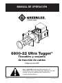
6800-22 Ultra Tugger
®
Cable Puller and Pulling Package
Serial Code ADB
INSTRUCTION MANUAL
Read and understand all of the instructions and
safety information in this manual before operating
or servicing this tool.
99938502 © 2015 Greenlee Textron Inc. IM 1529 REV 3 8/15
Español ............... 43
Français .............. 85

6800-22 Ultra Tugger
®
Cable Puller and Pulling Package
Greenlee / A Textron Company 4455 Boeing Dr. • Rockford, IL 61109-2988 USA • 815-397-7070
2
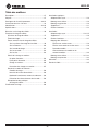
Table of Contents
Description .................................................................... 3
Purpose ......................................................................... 3
Important Safety Information ..................................... 4-7
Grounding Instructions .................................................. 8
Identication ............................................................. 9-10
Specications .............................................................. 11
Cable Pulling Glossary ................................................ 12
Cable Pulling Principles:
Cable Pulling Systems ............................................. 13
Pulling Theory .......................................................... 14
Cable Pulling Forces:
At the Cable Puller Anchoring System ................. 15
At the Capstan ..................................................... 16
At the Pulling Rope .............................................. 17
At the Connectors ................................................ 18
At the Sheaves ..................................................... 19
Calculating Hook Load:
One Attachment Point .......................................... 20
Two Attachment Points ........................................ 21
Hook Load ............................................................ 22
Hook Loads Illustrated ......................................... 23
Tailing the Rope:
Control of the Pull ................................................ 24
Amount of Tailing Force ....................................... 24
Number of Wraps of Rope around Capstan ........ 24
Preventing Rope Overlap ..................................... 24
Summary of Cable Pulling Principles....................... 25
Planning the Pull .......................................................... 25
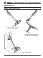
Typical Setups:
Pipe Adapter ............................................................ 26
Chain Mount ............................................................ 26
Floor Mount ............................................................. 26
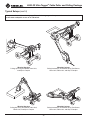
T-Stand .................................................................... 27
Wheeled Carriage .................................................... 28
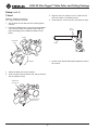
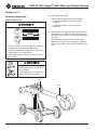
Setup:
Pipe Adapter ....................................................... 29-31
T-Stand .................................................................... 32
Wheeled Carriage .................................................... 33
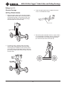
Mounting Components:
Boom with Nose Unit ........................................... 34
Booms with Elbow Unit and Nose Unit ................ 35
Slip-in Coupler ..................................................... 36
Straddling the Conduit with Slip-in Coupler ........ 36
Chain Mount ....................................................... 37-38
Floor Mount ............................................................. 39
Operation ..................................................................... 40
Removing Cable .......................................................... 41

6800-22 Ultra Tugger
®
Cable Puller and Pulling Package
Greenlee / A Textron Company 4455 Boeing Dr. • Rockford, IL 61109-2988 USA • 815-397-7070
3
KEEP THIS MANUAL
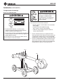
Description
The Greenlee Ultra Tugger
®
cable puller is intended
to be used to pull cable through conduit and in tray.
The Ultra Tugger will develop 35.6 kN (8000 lb) of pulling
force. See a Greenlee catalog for sheaves, pulling rope,
and other cable pulling acces–sories to create an entire
cable pulling system.
No single manual can provide instructions for every
possible cable pulling application; this manual contains
general information necessary to accomplish cable pulls
of many different setups.
Safety
Safety is essential in the use and maintenance of
Greenlee tools and equipment. This instruction manual
and any markings on the tools provide information for
avoiding hazards and unsafe practices related to use of
this tool. Observe all of the safety information provided.
Do not operate this tool unless fully trained to do so,
or under trained supervision.
Purpose of this Manual
This manual is intended to familiarize all personnel with
the safe operation and maintenance procedures for the
Greenlee 6800-22 Ultra Tugger cable pullers.
Keep this manual available to all personnel.
Replacement manuals are available upon request at no
charge at www.greenlee.com.
Other Publications
Service Manual: 99966174
All specications are nominal and may change as design
improvements occur. Greenlee Textron Inc. shall not be liable for
damages resulting from misapplication or misuse of its products.
Ultra Tugger is a registered trademark of Textron Innovations Inc.

6800-22 Ultra Tugger
®
Cable Puller and Pulling Package
Greenlee / A Textron Company 4455 Boeing Dr. • Rockford, IL 61109-2988 USA • 815-397-7070
4
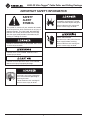
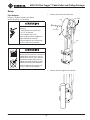
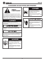
IMPORTANT SAFETY INFORMATION
SAFETY
ALERT
SYMBOL
This symbol is used to call your attention to hazards
or unsafe practices which could result in an injury or
property damage. The signal word, dened below,
indicates the severity of the hazard. The message
after the signal word provides information for pre-
venting or avoiding the hazard.
Immediate hazards which, if not avoided, WILL result
in severe injury or death.
Hazards which, if not avoided, COULD result in
severe injury or death.
Hazards or unsafe practices which, if not avoided,
MAY result in injury or property damage.
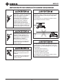
Read and understand all of the
instructions and safety information
in this manual before operating or
servicing this tool.
Failure to observe this warning will
result in severe injury or death.
Do not operate the cable puller in
a hazardous environment. Hazards
include ammable liquids and gases.
Failure to observe this warning will
result in severe injury or death.
Electric shock hazard:
Disconnect the cable puller from the
power supply before servicing.
Failure to observe this warning can
result in severe injury or death.

6800-22 Ultra Tugger
®
Cable Puller and Pulling Package
Greenlee / A Textron Company 4455 Boeing Dr. • Rockford, IL 61109-2988 USA • 815-397-7070
5
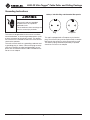
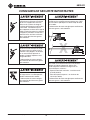
IMPORTANT SAFETY INFORMATION
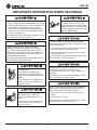
Inspect and verify the maximum
load-bearing capacity or maximum
strength of all structural supports,
pulling system components and
anchoring systems before setting
up the puller. Any component that
cannot withstand the maximum
cable-pulling forces may break and
strike nearby personnel with sufcient
force to cause severe injury
or death.
Do not allow anything other than the
pulling rope to contact the capstan.
A grip, swivel, or other component
could break and strike operator with
great force.
Failure to observe this warning can
result in severe injury or death.
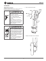
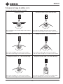
Do not stand directly under a vertical
pull. Cable could fall suddenly from
the conduit.
Failure to observe this warning can
result in severe injury or death.
Locate the puller so that it is close to the conduit.
Rope, cable, or connectors can break under tension,
causing the rope to whip violently.
Failure to observe this warning can result in severe
injury or death.
An under-rated or worn rope may break and whip
violently. Use a double-braided composite rope with
the following characteristics:
• Maximum Rated Capacity:
at least 35.6 kN (8000 lb)
• Average Breaking Strength:
at least 143 kN (32,000 lb)
Failure to observe this warning can result in severe
injury or death.

6800-22 Ultra Tugger
®
Cable Puller and Pulling Package
Greenlee / A Textron Company 4455 Boeing Dr. • Rockford, IL 61109-2988 USA • 815-397-7070
6
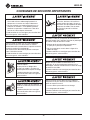
IMPORTANT SAFETY INFORMATION
• Check the condition of the entire rope before use.
A worn or damaged rope can break under tension
and whip violently.
• Do not maintain a stationary rope on a rotating
capstan. The wear generated may cause the rope
to break under tension and whip violently.
Failure to observe these warnings can result in severe
injury or death.
Attach the pulling rope to the cable with appropriate
types of connectors as described in this manual.
Select connectors with a maximum-rated capacity
of 35.6 kN (8000 lb). An under-rated connector can
break under tension.
Failure to observe this warning can result in severe
injury or death.
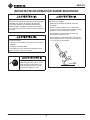
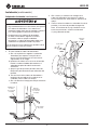
Shear Point:
Do not put ngers through holes in
elbow unit. Rotating parts may cut off
ngers.
Failure to observe this warning can
result in severe injury or death.
Keep hands away from the capstan.
Rope at the capstan can crush a
hand.
Failure to observe this warning can
result in severe injury or death.
Do not wrap rope around hands,
arms, waist or other body parts.
Do not stand in spent coils or tailed
rope. Hold rope so that it may be
released quickly.
Rope, cable, or a connecting device can break under
tension, causing the rope to whip violently.
Do not allow any unnecessary personnel to remain in
the area during the pull.
• Do not allow any personnel to stand in line with the
pulling rope.
Failure to observe these warnings can result in severe
injury or death.
Do not allow the rope to become overlapped on the
capstan. If an overlap begins to develop, relax the
tailing force immediately and shut off the cable puller.
Failure to observe this warning can result in severe
injury or death.
Use this tool for manufacturer’s intended purpose
only. Do not use the cable puller as a hoist or winch.
• The cable puller cannot lower a load.
• The load may fall.
Failure to observe this warning can result in severe
injury or death.

6800-22 Ultra Tugger
®
Cable Puller and Pulling Package
Greenlee / A Textron Company 4455 Boeing Dr. • Rockford, IL 61109-2988 USA • 815-397-7070
7
IMPORTANT SAFETY INFORMATION
Inspect puller and accessories before use. Replace
any worn or damaged components with Greenlee
replacement parts. A damaged or improperly assem-
bled item can break and strike nearby personnel with
sufcient force to cause severe injury or death.
Entanglement hazard:
• Do not operate the cable puller while wearing
loose-tting clothing.
• Retain long hair.
Failure to observe this warning can result in severe
injury or death.
Wear eye protection when using this
tool. Failure to wear eye protection
can result in severe eye injury from
ying debris.
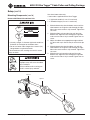
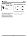
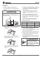
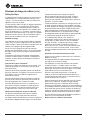
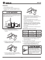
When using the wheeled carriage to transport the
Ultra Tugger:
• Keep personnel out of the path of transport.
• Evaluate the terrain over which the carriage is to
move. If in doubt, obtain additional help and move
the carriage slowly.
• Do not transport over inclines of more than 10°.
• Do not transport the carriage with boom tubes
longer than the supplied 3' and 4' tubes.
10°

6800-22 Ultra Tugger
®
Cable Puller and Pulling Package
Greenlee / A Textron Company 4455 Boeing Dr. • Rockford, IL 61109-2988 USA • 815-397-7070
8
Grounding Instructions
Electric shock hazard:
Connect this tool to a grounded
receptacle on a 16-amp GFCI-
protected circuit.
Failure to observe these warnings can
result in severe injury or death.
This tool must be grounded. In the event of a malfunc-
tion or breakdown, an electrical ground provides a path
of least resistance for the electric current. This path of
least resistance is intended to reduce the risk of electric
shock to the operator.
This tool’s electric cord has a grounding conductor and
a grounding plug as shown. Connect the plug to recep-
tacle that is properly installed and grounded in accor-
dance with all national and local codes and ordinances.
Do not use an adapter.
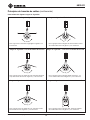
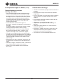
16-Amp / 230-Volt Plug and Grounded Receptacle
This tool is equipped with a European-style electrical
plug. The electrical plug can be replaced with a compat-
ible plug for the country in which the tool will be used.
The electrical plug should be replaced by a qualied
electrician. Do not use an adapter.
Plug Receptacle

6800-22 Ultra Tugger
®
Cable Puller and Pulling Package
Greenlee / A Textron Company 4455 Boeing Dr. • Rockford, IL 61109-2988 USA • 815-397-7070
9
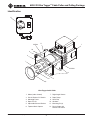
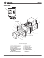
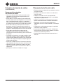
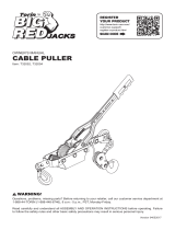
Identification
Ultra Tugger Cable Puller
1. Motor (under shroud) 7. Right Angle Sheave
2. Circuit Breaker / I/O Switch 8. Rope Ramp
3. Mounting Plates 9. Hitch Clip
4. Rope Tie-Off 10. Gearbox
5. Adjustable Sheave Bracket 11. Mounting Pin (2)
6. Tapered Steel Capstan 12. Force Gauge with
Remote I/O Switch
1
2
3
4
5
6
7
9
11
Lift Point
Lift Point
10
8
12

6800-22 Ultra Tugger
®
Cable Puller and Pulling Package
Greenlee / A Textron Company 4455 Boeing Dr. • Rockford, IL 61109-2988 USA • 815-397-7070
10
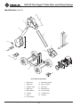
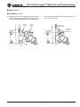
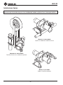
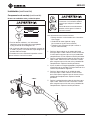
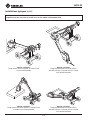
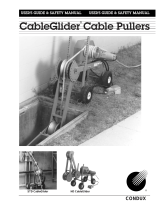
Identification (cont’d)
Versi-Boom Components
1. Elbow Unit 9. Wheeled Carriage
2. Sight Hole 10. Slip-in Coupler
3. 4' Boom Tube 11. Nose Unit
4. Sight Hole 12. Mounting Pins
5. Boom Mount 13. Hitch Pin Clips
6. T-Stand 14. 3' Boom Tube
7. Puller 15. Long Pin
8. Force Gauge
7
1
14
11
13
12
10
2
3
5
9
6
4
15
8

6800-22 Ultra Tugger
®
Cable Puller and Pulling Package
Greenlee / A Textron Company 4455 Boeing Dr. • Rockford, IL 61109-2988 USA • 815-397-7070
11
Specifications
Weight ........................................................................................................ 43 kg (95 lb)
Dimensions:
Length ................................................................................................. 29 cm (11.5")
Width ....................................................................................................... 68 cm (27")
Height .....................................................................................................25 cm (9.8")
Motor:
Voltage ..................................................................230 VAC, 50/60 Hz, single phase
Current Draw at Full Load .......................................................................... 9.5 amps
Sound Level ............................................................................................. Lwa 70 at 1 m
Power Source ............................................230 VAC, 50/60 Hz, 16 amps, single phase
Speed:
No Load.................................................................................... 2.74 m/min (9 ft/min)
8900 N (2000 lb) ....................................................................... 2.44 m/min (8 ft/min)
17.8 kN (4000 lb) ................................................................... 2.29 m/min (7.5 ft/min)
26.7 kN (6000 lb) ...................................................................... 2.13 m/min (7 ft/min)
35.6 kN (8000 lb) ...................................................................... 1.83 m/min (6 ft/min)
Pulling Force:
0 kN to 17.8 kN (0 lb to4000 lb) .............................................Continuous operation
17.8 kN to 35.6 kN (4000 lb to 8000 lb) ...................................... 5 minutes per hour
Pulling Rope:
Required Rope ...................................................................22.2 mm (7/8") diameter,
double-braided, polyester composite
Average Breaking Strength .......................................... 143 kN (32,000 lb) minimum
IP Rating:
Motor .................................................................................................................. IP23
Ultra Tugger and Force Gauge Enclosure .......................................................... IP54
Temperature Rating:
Transportation and Storage ................................. 55 °C to -25 °C (131 °F to -13 °F)
Elevation Rating ......................................................... 1000 m (3280 ft) above sea level

6800-22 Ultra Tugger
®
Cable Puller and Pulling Package
Greenlee / A Textron Company 4455 Boeing Dr. • Rockford, IL 61109-2988 USA • 815-397-7070
12
anchoring system
any item or group of items that keeps a cable pulling
component in place during the cable pull
capstan
the hollow cylinder of the cable puller that acts on the
pulling rope to generate pulling force
coefficient of friction
the ratio that compares two amounts of force:
(1) the force needed to move an object over a surface
and (2) the force holding the object against the surface
This ratio is used to describe how the capstan and the
rope work together.
connector
any item, such as a wire grip, clevis, swivel, or pulling
grip, that connects the rope to the cable
direct line of pull
the areas next to the pulling rope and along its path;
this includes the areas in front of, in back of, and under-
neath the rope
maximum rated capacity
the amount of pulling tension that any component
can safely withstand, rated in kilonewtons (metric)
or pounds; the maximum rated capacity of every
component must meet or exceed the maximum pulling
force of the cable puller
Newton
a metric unit of force, equivalent to 0.225 pounds of
force
pipe adapter sheave
attaches to conduit for pulling or feeding cable
pulling grip
connects the rope to the cable; consists of a wire mesh
basket that slides over the cable and grips the insulation
pulling force
the amount of pulling tension developed by the cable
puller, rated in newtons (metric) or pounds; a cable
puller is usually described by the maximum pulling force
that it can develop
Cable Pulling Glossary
resultant force
any force that is produced when two or more forces act
on an object; applies to the sheaves of a cable pulling
system
rope ramp
a device that works with a tapered capstan; guides the
rope onto the capstan to prevent rope overlap
sheave
a pulley that changes the direction of the rope and cable
stored energy
the energy that accumulates in the pulling rope as it
stretches, described in newton-meters (metric) or
foot-pounds
support structure
any stationary object that a cable pulling system
component is anchored to, such as a concrete oor
(for the oor mount) or an I-beam (for a sheave)
tactile feedback
the way the rope feels as it feeds off of the capstan; the
feel of the rope provides information about the progress
of the pull to the operator
tail
the portion of the rope that the operator applies force
to; this is the rope coming off of the capstan, and is not
under the tension of the pull
tailing the rope
the operator’s main function; this is the process of
applying force to the tail of the pulling rope—see the
complete explanation under Principles of Cable Pulling
wire grip
connects the rope to the cable; some use a set screw to
clamp onto the conductors of the cable

6800-22 Ultra Tugger
®
Cable Puller and Pulling Package
Greenlee / A Textron Company 4455 Boeing Dr. • Rockford, IL 61109-2988 USA • 815-397-7070
13
Cable Pulling Principles
Pulling cable is a complex process. This section of
the manual describes and explains four main topics of
pulling cable:
• each cable pulling system component
• how these components work together
• forces that are generated
• procedures for the cable puller operator to follow
While reading through this section of the manual, look
for components that are shaded in the illustrations. The
shading indicates components that are associated with
the text.
Greenlee strongly recommends that each member of
the cable pulling crew review this section of the manual
before each cable pull.
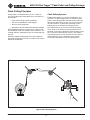
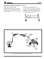
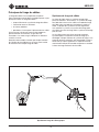
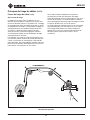
Cable Pulling Systems
Pulling cable requires a system of components. At a
minimum, a cable pulling system will include a cable
puller, a cable pulling rope, and connectors to join the
rope to the cable. Most systems will also include, but
are not limited to, a cable puller anchoring system,
pulling sheaves and sheave anchoring systems.
The cable puller has a maximum amount of pulling
force, which is the amount of pulling tension that it
develops. Every other component of the pulling system
has a maximum rated capacity, which is the amount
of pulling tension that it can withstand. The maximum
rated capacity of every component must meet or
exceed the cable puller’s maximum pulling force.
Typical Cable Pulling System

6800-22 Ultra Tugger
®
Cable Puller and Pulling Package
Greenlee / A Textron Company 4455 Boeing Dr. • Rockford, IL 61109-2988 USA • 815-397-7070
14
Cable Pulling Principles (cont’d)
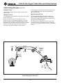
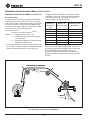
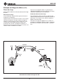
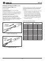
Cable Pulling Theory Illustrated
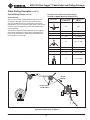
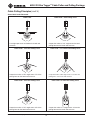
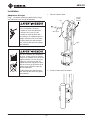
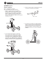
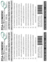
Pulling Theory
This section introduces the main ideas involved with
pulling cable.
Pulling Resistance
The cable puller must overcome two types of resistance:
gravity and friction.
Gravity constantly exerts its force on the vertical
portions of the run. When the pulling force is relaxed,
gravity attempts to pull the cable downward. Friction
develops where the cable contacts the sheaves, conduit
and tray. Friction resists any movement, forward or
backward, and tends to hold the cables in place.
To accomplish a cable pull, the cable pulling system
must develop more force than the combination of
gravity and friction.
Generating Pulling Force
To generate pulling force, the capstan works as a
force multiplier. The operator exerts a small amount
of force on the rope. The cable puller multiplies this
and generates the pulling force.
This pulling force is applied to the rope, connectors,
and cable in order to accomplish the pull. The direc-
tion of force is changed, where necessary, with pulling
sheaves.
Gravity
Weight
of Cable
Conduit
Friction
Tailing
Force
Pulling Force
35.6 kN
(8000 lb)

6800-22 Ultra Tugger
®
Cable Puller and Pulling Package
Greenlee / A Textron Company 4455 Boeing Dr. • Rockford, IL 61109-2988 USA • 815-397-7070
15
Cable Pulling Principles (cont’d)
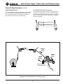
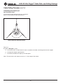
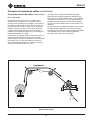
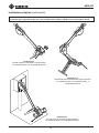
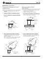
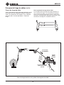
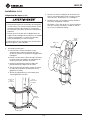
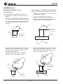
Pulling Force at the Cable Puller’s Anchoring System
Cable Pulling Forces
This section provides detailed explanations and illustra-
tions of the forces that are generated during the cable
pull. These explanations are based on the concepts
presented in the last section, Pulling Theory.
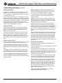
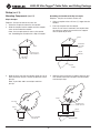
At the Cable Puller Anchoring System
The cable puller will exert its maximum pulling force on
cable puller’s anchoring system. It is extremely import-
ant the anchoring system can withstand this amount of
force. Refer to “Typical Setup: Floor Mount” for proper
setup or installation.
35.6 kN
(8000 lb)
Maximum
35.6 kN
(8000 lb)
Maximum
Pulling Force
35.6 kN
(8000 lb)
Maximum Pulling Force
at Anchoring System

6800-22 Ultra Tugger
®
Cable Puller and Pulling Package
Greenlee / A Textron Company 4455 Boeing Dr. • Rockford, IL 61109-2988 USA • 815-397-7070
16
Cable Pulling Principles (cont’d)
Cable Pulling Forces (cont’d)
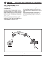
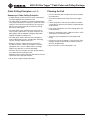
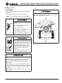
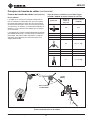
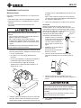
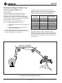
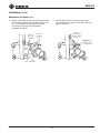
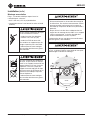
At the Capstan
The capstan acts as a force multiplier. The operator
exerts a small amount of tension, or tailing force, on the
rope; the capstan multiplies this force to pull the cable.
The resultant force depends upon the number of times
the rope is wrapped around the capstan, as shown in
the formula below.
Pulling Force = Tailing Force x e
0.0175µø
Where: e = the natural logarithm, or 2.7183
µ = the coefcient of friction between the
rope and the capstan*
ø = the number of degrees of wrap of rope
around the capstan
* The average value for the coefcient of friction when
double-braided composite rope is pulled over a clean
dry capstan is 0.125.
The following table is based on the formula above.
The input, or tailing force, is constant at 44.5 N (10 lb).
Increasing the number of wraps increases
the pulling force.
Operator’s
TailingForce
Number of
Wraps of Rope
Approximate
PullingForce
44.5 N (10 lb) 1 93.4 N (21 lb)
44.5 N (10 lb) 2 213.5 N (48 lb)
44.5 N (10 lb) 3 474.9 N (106 lb)
44.5 N (10 lb) 4 1043.8 N (233 lb)
44.5 N (10 lb) 5 2293.7 N (512 lb)
44.5 N (10 lb) 6 5048.9 N (1127 lb)
44.5 N (10 lb) 7 11.1 kN (2478 lb)
This table shows how the capstan acts as a force
multiplier. Because the coefcient of friction depends
upon the condition of the rope and capstan, this formula
cannot determine an exact amount of pulling force.
The Capstan as a Force Multiplier
Pulling Force: 35.6 kN (8000 lb)
Tailing
Force

6800-22 Ultra Tugger
®
Cable Puller and Pulling Package
Greenlee / A Textron Company 4455 Boeing Dr. • Rockford, IL 61109-2988 USA • 815-397-7070
17
Cable Pulling Principles (cont’d)
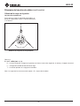
Stored Energy
Stored Energy
Cable Pulling Forces (cont’d)
At the Pulling Rope
The product of a force (f) moving through a distance
(d) is energy (f x d), and may be measured in newton-
meters or foot-pounds. Energy is stored in a rope when
the rope is stretched. This is similar to the way energy is
stored in a rubber band when it is stretched. Failure of
the rope or any other component of the pulling system
can cause a sudden uncontrolled release of the energy
stored in the rope.
For example, a 100-meter nylon rope with a 50,000
newton average breaking strength could stretch 40
meters and store 1,000,000 joules of energy. This is
enough energy to throw a 900-kilogram object, such as
a small automobile, 113 meters into the air.
A similar double-braided composite rope could store
approximately 300,000 joules of energy. This could
throw the same object only 34 meters into the air.
The double-braided composite rope stores much less
energy and has much less potential for injury if it were to
break.
Double-braided composite rope is the only type of
rope recommended for use with the Ultra Tugger cable
puller. Select a double-braided composite rope with
an average rated breaking strength of at least 143 kN
(32,000 lb).

6800-22 Ultra Tugger
®
Cable Puller and Pulling Package
Greenlee / A Textron Company 4455 Boeing Dr. • Rockford, IL 61109-2988 USA • 815-397-7070
18
Cable Pulling Principles (cont’d)
Cable Pulling Forces (cont’d)
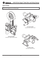
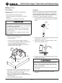
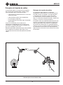
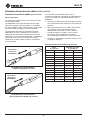
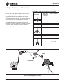
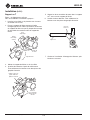
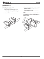
At the Connectors
The connectors will be subjected to the cable puller’s
maximum pulling force.
Several types of rope connectors—clevises, swivels,
and rope-to-swivel connectors—are available. Follow
the instructions provided with each to provide a good
connection.
Two types of wire connectors—wire grips and pulling
grips—are available. The wire grip uses a set screw
to clamp onto the conductors of the cable. The pulling
grip consists of a wire mesh basket that slides over
the cable and grips the insulation.
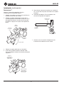
When selecting a pulling grip, it is extremely important
to select a grip of the correct (1) type, (2) size, and (3)
maximum rated capacity.
1. Select the correct type based on the descriptions
of each type in the Greenlee catalog.
2. Measure the circumference of the wire bundle.
(To do this accurately, fasten a tie strap around the
bundle. Cut off and discard the tail. Then cut the tie
strap and measure its length.). Use the table pro-
vided to nd the correct size.
3. See the maximum rated capacities in the Greenlee
catalog.
Pulling Grip Size Table
Circumference Range Required Grip Diameter
inch mm inch mm
1.57–1.95 39.9–49.5 0.50–0.61 12.7–15.5
1.95–2.36 49.5–59.9 0.62–0.74 15.8–18.8
2.36–3.14 59.9–79.8 0.75–0.99 19.1–25.1
3.14–3.93 79.8–99.8 1.00–1.24 25.4–31.5
3.93–4.71 99.8–119.6 1.25–1.49 31.8–37.8
4.71–5.50 119.6–139.7 1.50–1.74 38.1–44.2
5.50–6.28 139.7–159.5 1.75–1.99 44.5–50.5
6.28–7.85 159.5–199.4 2.00–2.49 50.8–63.2
7.85–9.42 199.4–239.3 2.50–2.99 63.5–75.9
9.42–11.00 239.3–279.4 3.00–3.49 76.2–88.6
11.00–12.57 279.4–319.3 3.50–3.99 88.9–101.3
12.57–14.14 319.3–359.2 4.00–4.49 101.6–114.0
14.14–15.71 359.2–399.0 4.50–4.99 114.3–126.7
A Typical Grip Setup—Clevis and Wire Grip
A Typical Grip Setup—Swivel and Pulling Grip
Maximum
Pulling Force
35.6 kN
(8000 lb)
Maximum
Pulling Force
35.6 kN
(8000 lb)

6800-22 Ultra Tugger
®
Cable Puller and Pulling Package
Greenlee / A Textron Company 4455 Boeing Dr. • Rockford, IL 61109-2988 USA • 815-397-7070
19
Cable Pulling Principles (cont’d)
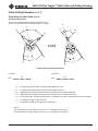
Typical Resultant Force at Sheave
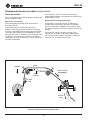
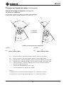
Cable Pulling Forces (cont’d)
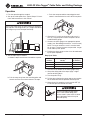
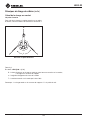
At the Sheaves
Sheaves are used to change the direction of the pull.
A change in direction creates a new resultant force
that may be greater than the cable puller’s maximum
pulling force. This new resultant force exerts itself on the
sheaves, sheave anchoring system, and support struc-
tures illustrated.
The resultant amount of force depends on the angle of
the change in direction. A brief table is provided here.
Refer to “Calculating the Hook Load” to determine the
resultant force at any angle.
Resultant Force Table for the Ultra Tugger
(35.6 kN or 8000 lb Maximum Pulling Force)
Illustration
Angle of Change
in Direction
Resultant Force
kN (lb)
180° 0 (0)
150° 18.5 (4160)
135° 27.4 (6160)
120° 35.6 (8000)
90° 50.2 (11,300)
60° 61.6 (13,800)
45° 65.8 (14,800)
30° 68.7 (15,400)
0° 71.2 (16,000)
Resultant Force =
27.4 kN (6160 lb)
35.6 kN
(8000 lb)
135

6800-22 Ultra Tugger
®
Cable Puller and Pulling Package
Greenlee / A Textron Company 4455 Boeing Dr. • Rockford, IL 61109-2988 USA • 815-397-7070
20
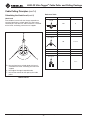
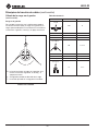
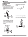
Formula 1:
R = 2 x T x SIN ((180 – θ) / 2)
R – the resultant force, or hook load; this force is exerted on the hook, anchoring and structural support
θ – the angle of change in rope direction
T – the tension exerted on the rope by the cable puller
Note: The total load on the support structure = R + the weight of the sheave.
Sheave with One Attachment Point
Cable Pulling Principles (cont’d)
Calculating the Hook Load
One Attachment Point
To calculate the hook load exerted at one attachment
point, use the Reference Table and Formula 1.
R
T
T
θ
Page is loading ...
Page is loading ...
Page is loading ...
Page is loading ...
Page is loading ...
Page is loading ...
Page is loading ...
Page is loading ...
Page is loading ...
Page is loading ...
Page is loading ...
Page is loading ...
Page is loading ...
Page is loading ...
Page is loading ...
Page is loading ...
Page is loading ...
Page is loading ...
Page is loading ...
Page is loading ...
Page is loading ...
Page is loading ...
Page is loading ...
Page is loading ...
Page is loading ...
Page is loading ...
Page is loading ...
Page is loading ...
Page is loading ...
Page is loading ...
Page is loading ...
Page is loading ...
Page is loading ...
Page is loading ...
Page is loading ...
Page is loading ...
Page is loading ...
Page is loading ...
Page is loading ...
Page is loading ...
Page is loading ...
Page is loading ...
Page is loading ...
Page is loading ...
Page is loading ...
Page is loading ...
Page is loading ...
Page is loading ...
Page is loading ...
Page is loading ...
Page is loading ...
Page is loading ...
Page is loading ...
Page is loading ...
Page is loading ...
Page is loading ...
Page is loading ...
Page is loading ...
Page is loading ...
Page is loading ...
Page is loading ...
Page is loading ...
Page is loading ...
Page is loading ...
Page is loading ...
Page is loading ...
Page is loading ...
Page is loading ...
Page is loading ...
Page is loading ...
Page is loading ...
Page is loading ...
Page is loading ...
Page is loading ...
Page is loading ...
Page is loading ...
Page is loading ...
Page is loading ...
Page is loading ...
Page is loading ...
Page is loading ...
Page is loading ...
Page is loading ...
Page is loading ...
Page is loading ...
Page is loading ...
Page is loading ...
Page is loading ...
Page is loading ...
Page is loading ...
Page is loading ...
Page is loading ...
Page is loading ...
Page is loading ...
Page is loading ...
Page is loading ...
Page is loading ...
Page is loading ...
Page is loading ...
Page is loading ...
Page is loading ...
Page is loading ...
Page is loading ...
Page is loading ...
Page is loading ...
Page is loading ...
-
 1
1
-
 2
2
-
 3
3
-
 4
4
-
 5
5
-
 6
6
-
 7
7
-
 8
8
-
 9
9
-
 10
10
-
 11
11
-
 12
12
-
 13
13
-
 14
14
-
 15
15
-
 16
16
-
 17
17
-
 18
18
-
 19
19
-
 20
20
-
 21
21
-
 22
22
-
 23
23
-
 24
24
-
 25
25
-
 26
26
-
 27
27
-
 28
28
-
 29
29
-
 30
30
-
 31
31
-
 32
32
-
 33
33
-
 34
34
-
 35
35
-
 36
36
-
 37
37
-
 38
38
-
 39
39
-
 40
40
-
 41
41
-
 42
42
-
 43
43
-
 44
44
-
 45
45
-
 46
46
-
 47
47
-
 48
48
-
 49
49
-
 50
50
-
 51
51
-
 52
52
-
 53
53
-
 54
54
-
 55
55
-
 56
56
-
 57
57
-
 58
58
-
 59
59
-
 60
60
-
 61
61
-
 62
62
-
 63
63
-
 64
64
-
 65
65
-
 66
66
-
 67
67
-
 68
68
-
 69
69
-
 70
70
-
 71
71
-
 72
72
-
 73
73
-
 74
74
-
 75
75
-
 76
76
-
 77
77
-
 78
78
-
 79
79
-
 80
80
-
 81
81
-
 82
82
-
 83
83
-
 84
84
-
 85
85
-
 86
86
-
 87
87
-
 88
88
-
 89
89
-
 90
90
-
 91
91
-
 92
92
-
 93
93
-
 94
94
-
 95
95
-
 96
96
-
 97
97
-
 98
98
-
 99
99
-
 100
100
-
 101
101
-
 102
102
-
 103
103
-
 104
104
-
 105
105
-
 106
106
-
 107
107
-
 108
108
-
 109
109
-
 110
110
-
 111
111
-
 112
112
-
 113
113
-
 114
114
-
 115
115
-
 116
116
-
 117
117
-
 118
118
-
 119
119
-
 120
120
-
 121
121
-
 122
122
-
 123
123
-
 124
124
-
 125
125
-
 126
126


Greenlee 6800-22 6802-22 6805-22 Ultra Tugger ADB User manual
- Category
- Toys
- Type
- User manual
Ask a question and I''ll find the answer in the document
Finding information in a document is now easier with AI
in other languages
Related papers
-
Greenlee Ultra Tugger User manual
-
Greenlee Ultra Tugger User manual
-
Greenlee Ultra Tugger User manual
-
-
-
-
-
-
-
Greenlee 658 Tray Type Sheave User manual
Other documents
-
 Big Red T32054 User manual
-
Toro Capstan Adaptor, Dingo Compact Utility Loader Installation guide
-
CHANCE Series 90 Capstan Hoist Owner's manual
-
Attwood 13710-4 Installation guide
-
Hubbell P308-0880 Owner's manual
-
 Condux Power Cable Pullers Owner's manual
-
 Portable Winch PCA-1213M2ESC Owner's manual
-
Delta Faucet 9158-SW-DST Installation guide
-
MB QUART Reference series User manual
-
Legrand XEVPED1 User manual


