tekmar 519 Installation guide

Category
Space heaters
Type
Installation guide

This manual is also suitable for

1. Location
Exterior
Wall
Interior
Wall
Behind
Door
5 feet
1.5 m
2. Remove Mounting Base
3. Installation to Wall
Wall
Thermostat
Front
Thermostat
Base
519
_
Q
06/16
Zoning
Replaces: 02/14
© 2016 tekmar 519
_
Q - 06/16
Radiant Thermostat 519
Quick Set-up Guide
2 of 12
© 2016 tekmar 519
_
Q - 06/16
3
1
/4
(83 mm)
Stud
Gang
Box
Thermostat
Front
Thermostat
Base
Adapter Plate 012
4. Installation to Gang Box
5. Wiring
6. User Interface
Away
L N
R
C
518
R Rh W1 S1 Com
No Power
C
518
R Rh W1 S1 Com
No Power
C
519
R Rh W1 S1 Com Away
No Power
Zone
Valve
24 V
C
Optional
Slab Sensor 079
Install field
jumper wire
R to Rh
Do not over
tighten wiring
screws. Hand
tighten only.
© 2016 tekmar 519
_
Q - 06/16
3 of 12
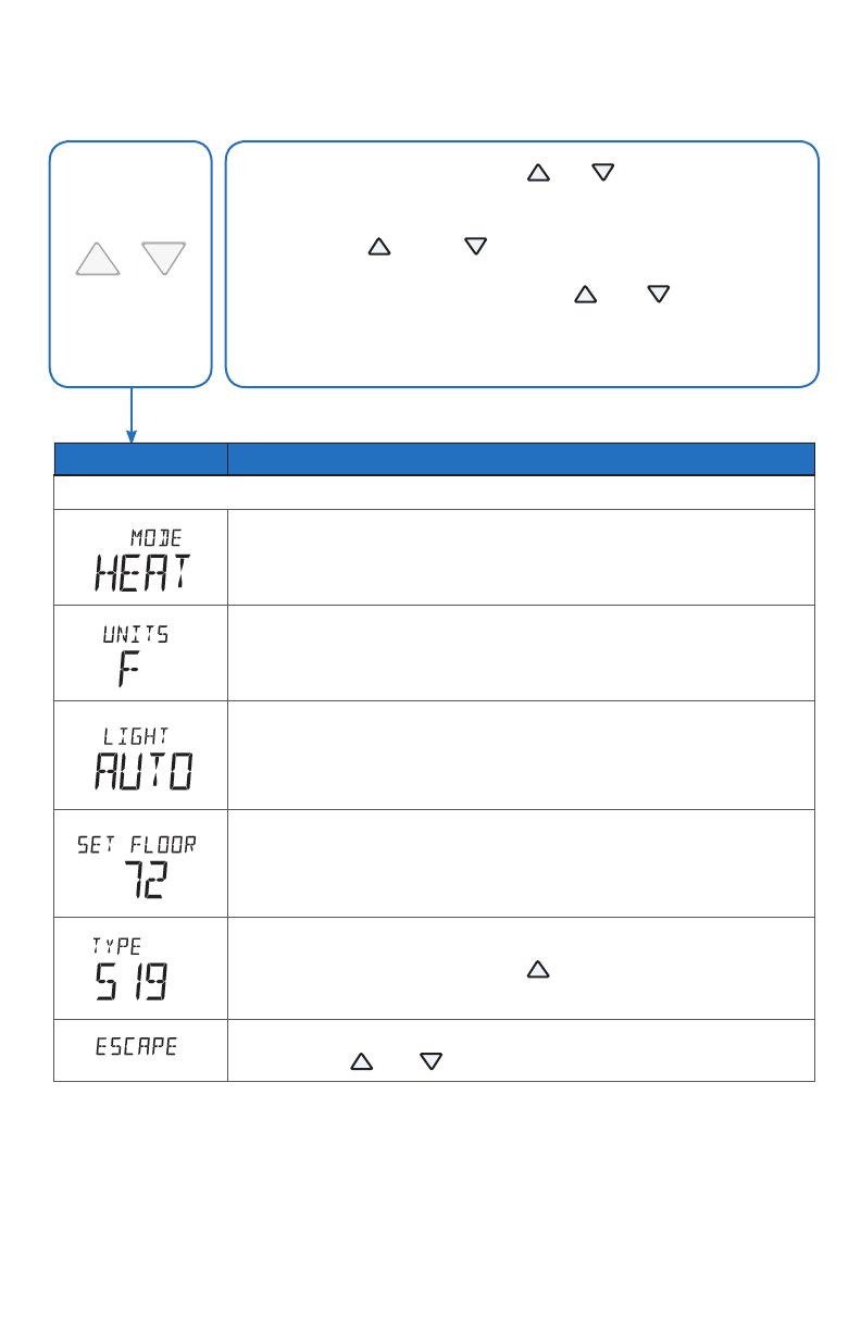
7. Critical Settings
Press and hold down both the and buttons for 3 seconds
to change from one step to the next.
Release both buttons once the step has been reached.
Press the
or the
button to change the setting, if
available.
Press and hold down both the
and
buttons for 3
seconds to go to the next step, OR
After 15 seconds of no button activity, the display goes
back to normal operation.
The following settings are essential to the successful operation of the heating system.
Press
+
Together
Display Setting
User settings.
MODE
Select heat or off.
UNITS
Select the temperature units in degree Fahrenheit or Celsius.
BACK LIGHT
Select when the display back light should operate. Options
are Off, Auto, and On. Auto operates the backlight for 30
seconds after a keystroke.
F
SET FLOOR
Set the floor minimum temperature. Available when an
auxiliary floor sensor is connected and the built-in room
temperature sensor is on.
TYPE
Device Type number. Hold the button to view the software
version.
ESCAPE
Release the
and buttons to return to the home screen.
Display Setting
Installer settings. Press the
and
buttons together for 5 more seconds.
AUXILIARY SENSOR
Select the type of auxiliary sensor. Available when an auxiliary
sensor is automatically detected. NONE = no auxiliary sensor,
ROOM = Indoor Sensor, OUT = Outdoor Sensor, FLOR = Slab
Sensor
Room
ROOM SENSOR
Select if the built-in room temperature sensor is on or off. The
built-in room sensor can only be disabled when an auxiliary room
or slab sensor is connected.
F
MAX
FLOOR MAXIMUM
Set the floor maximum temperature in order to protect the floor
covering. Suggested settings: Tile = 90°F (32°C), Wood Floor =
85°F (29°C)
F
SET AWAY
Set the away temperature.
ESCAPE
Release the
and
buttons to return to the home screen.
For a full list of settings and operational details, please refer to the
thermostat Installation and Operation Manual 519_D that is available from
tekmarControls.com
519
_
Q - 06/16 4 of 12 © 2016 tekmar
Tel: (250) 545-7749 • Fax: (250) 984-0815
tekmarControls.com
All specications are subject to change without notice.
Mur
Façade du
thermostat
Base de
thermostat
1. Emplacement
2. Retirez la base de montage
3. Installation au mur
Mur extérieur
Mur intérieur
5 pi.
1,5 m
Derrière
porte
519
_
Q
06/16
Zonage
Remplace:
02/14
Radiant Thermostat 519
Guide d’installation rapide
5 of 12
© 2016 tekmar 519
_
D - 06/16
1. Ubicación
Pared
exterior
Pared
interior
5 pies
1,5 m
2. Quite la base de montaje
3. Instalación de la
base de montaje
Wall
Thermostat
Front
Thermostat
Base
Frente del
termostato
Base del
termostato
Pared
519
_
Q
06/16
División en
zonas
Remplazado
por: 02/14
Detrás
de la puerta
Radiant Thermostat 519
Guía de instalación rápida
9 of 12
© 2016 tekmar 519
_
Q - 06/16
  • Page 1 1
  • Page 2 2
  • Page 3 3
  • Page 4 4
  • Page 5 5
  • Page 6 6
  • Page 7 7
  • Page 8 8
  • Page 9 9
  • Page 10 10
  • Page 11 11
  • Page 12 12

tekmar 519 Installation guide

Category
Space heaters
Type
Installation guide
This manual is also suitable for

Ask a question and I''ll find the answer in the document

Finding information in a document is now easier with AI

in other languages