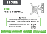
Sanus VML41 Installation guide

Category
Flat panel wall mounts
Type
Installation guide
VML
41
Instruction Manual
We’ll Make It Stress-Free
If you have any questions along the way, just give us a call.
1-800-359-5520 (UK: 0800-056-2853)
We’re ready to help!
Texto en español, página 14
Texte français page 16
Deutscher Text Seiten 18
Nederlandse tekst op pagina 20
Svensk text sida 22
本語は 24 ージ
中文文字说明请参见第 26
Русский текст: стр. 28
ES
FR
DE
NL
SV
JA
ZH
RU
2
IMPORTANT SAFETY INSTRUCTIONS
– SAVE THESE INSTRUCTIONS PLEASE READ ENTIRE MANUAL PRIOR TO USE
No
Perfect!
Yes
This mount is NOT compatible. Visit MountFinder.Sanus.com or call
1-800-359-5520 (UK: 0800-056-2853) tond a compatible mount.
Please read through these instructions completely to be sure you’re comfortable with this easy install process.
Also check your TV owner’s manual to see if there are any special requirements for mounting your TV.
If you do not understand these instructions or have doubts about the safety of the installation, assembly or use
of this product, contact Customer Service at 1-800-359-5520 (UK: 0800-056-2853).
Do you have all of
the tools needed?
Before getting started, let’s make sure this mount is perfect for you!
1
2
3
4
What is your
wall made of?
Drywall with
wood studs?
36 kg
(80 lbs)
CAUTION: Avoid potential personal injuries and property damage!
This product includes directions and hardware for use with wood studs, solid concrete and concrete block walls
DO NOT install into drywall alone.
The wall must be capable of supporting five times the weight of the TV and mount combined.
Do not use this product for any purpose not explicitly specified by manufacturer.
Manufacturer is not responsible for damage or injury caused by incorrect assembly or use.
Perfect! Perfect!
Ready to begin?
Does your TV weigh
more than 36 kg
(80 lbs) including
accessories?
CAUTION:
DO NOT install
into drywall alone
Solid concrete or
concrete block?
Unsure?
Call Customer Service:
1-800-359-5520
(UK: 0800-056-2853)
Included Wood Stud Applications Concrete Applications
3.2 mm (1/8 in.)
Wood
8 mm (5/16 in.)
Concrete
Screwdriver
Tape
Measure
Stud Finder HammerAwl
Pencil
Drill Bit Drill Bit
Electric
Drill
Square Driver Bit
3
#10 x 2 1/2 in.
2.5mm
22mm
M4/M5
M6/M8
UX8x50R
M4 x 35mm
M4 x 12mm
M5 x 12mm
M5 x 35mm
M6 x 35mm
M6 x 20mm
M6 x 12mm
M8 x 16mm
M8 x 35mm
M8 x 50mm
M8 x 20mm
M8 x 25mm
Parts and Hardware
WARNING: This product contains small items that could be a choking hazard if swallowed. Before starting assembly, verify all parts are included and
undamaged. If any parts are missing or damaged, do not return the damaged item to your dealer; contact Customer Service. Never use damaged parts!
*
WARNING: This product contains a magnet. If an implanted medical device such as a pacemaker or implantable cardioverter defibrillator (ICD) is
in use, magnetic fields may aect the operation of those devices, resulting in serious injury or death. If you have an implanted medical device, keep at least
13 cm (5 in.) between your device and the magnet. Please consult with your physician or medical professional prior to using this product.
NOTE: Not all hardware included will be used.
TV Bracket
TV Screws
TV Washers
Spacers
Wall Plate
Concrete Anchors
Washers
Stando
*
(Magnetic Leveling Feet)
Disc
(Adhesive backed)
Wood Screws (Wall Plate Screws)
Driver Bit (Square)
For concrete installations ONLY
CAUTION:
Do not use in drywall or wood
02
x2
03
x2
01 x1
18 x1
04 x2
05 x2
06 x2
07 x2
08 x2
09 x2
10 x2
11 x2
12 x2
13 x2
14 x2
15 x2
16 x2
23 x2
24 x2
19 x2
21
x2
20
x2
22
x2
17 x2
Parts and Hardware for STEP 1 Parts and Hardware for STEP 2
Parts for STEP 3 (OPTIONAL)
4
1
Attach TV Bracket to TV
1-1 Select Your TV Screws
CAUTION: Verify thread engagment of the screw
or spacer/screw combination in STEP 1-2.
Too long will damage the TV.
Too short will not hold the TV.
Too Short
Correct
Correct
Too Long
M4
M5
M6
M8
5
Attach TV Bracket to TV
1-2 Attach the TV Bracket
Flat Back TV [AND TV closer to the wall]
Rounded Back TV
Extra Space Needed
[for cables or inset holes]
A B
B
Inset Holes
Cables
A
01
01
02
04
03
05 06 07 08 09
Top of TV
Top of TV
10
11 12 13 14
0216 17
15
03
16 17
6
2A
Attach Wall Plate to Wall
CAUTION: Avoid potential personal injuries
and property damage!
Drywall covering the wall must not exceed
16 mm (5/8 in.)
Minimum wood stud size: common 51 x 102 mm
(2 x 4 in.) nominal 38 x 89 mm (1½ x 3½ in.)
Minimum horizontal space between fasteners:
406 mm (16 in.)
Stud centers must be verified – not all walls
have conventional 406 mm (16 in.)
2-1A Verify Your Wall 2-2A Find the Stud Centers
WOOD STUD OPTION
1 2 3
Max.
16 mm
(5/8 in.)
Min.
406 mm
(16 in.)
Min. 38 mm (1 1/2 in.)
Min. 89 mm (3 1/2 in.)
7
Attach Wall Plate to Wall
2-3A Attach the Wall Plate
1
2
3
CAUTION: Improper use could reduce the holding power
of screws
22
. DO NOT over-tighten the screws.
Go to STEP 3 on PAGE 10.
18
18
2219 21
IMPORTANT: 3.2 mm (1/8 in.)
pilot holes must be drilled to a
depth of 63 mm (2.5 in.).
63 mm (2.5 in.)
3.2 mm
(1/8 in.)
8
2B
Attach Wall Plate to Wall
2-1B Verify Your Wall
SOLID CONCRETE AND CONCRETE BLOCK OPTION
CAUTION: Avoid potential personal injuries and property damage!
Minimum solid concrete thickness: 203 mm (8 in.)
Minimum concrete block size: 203 x 203 x 406 mm (8 x 8 x 16 in.)
Minimum horizontal space between fasteners: 406 mm (16 in.)
Mount wall plate
18
directly onto the concrete surface
Min.
203 mm
(8 in.)
Min. 406 mm
(16 in.)
2-2B Attach the Wall Plate
Min.
203 mm
(8 in.)
18
1
Min. 406 mm
(16 in.)
9
Attach Wall Plate to Wall
IMPORTANT: 8 mm (5/16 in.) pilot
holes must be drilled to a depth of
70 mm (2.75 in.).
Never drill into the mortar between blocks.
CAUTION: Be sure the anchors
20
are seated flush with the
concrete surface.
CAUTION: Improper use could
reduce the holding power of screws
22
. DO NOT over-tighten the screws.
002862.eps
8 mm
(5/16 in.)
70 mm (2.75 in.)
18
19 22
20
2 3 4
21
10
3
Attach TV to Wall Plate
3-1 Unlock the Wall Plate 3-2 Hang Your TV
HEAVY! You may need assistance with this step.
Side View
18
1801
01
18
IMPORTANT: DO NOT lower TV straight down onto
wall plate
18
-- this will engage the lock. Safety latch must
be released for proper installation (See STEP 3-1).
11
Attach TV to Wall Plate
Side View
3-3 Lock the Wall Plate
CAUTION: Avoid potential personal injury or property
damage! The locking mechanism must be locked, so the TV
is securely fastened to the wall plate
18
.
18
01
18
Side View Side View
Button
12
3-4 No Tilt Feature (OPTIONAL)
For non-metal back TVs, use adhesive disc
24
. For non-metal back TVs, use adhesive disc
24
.
2324
17
2324
A B
Attach TV to Wall Plate (continued)
13
Adjustments
LevelLateral Shift Remove the TV
Slide the TV side to side.
Make sure your TV is locked to wall
plate
18
(STEP 3-3).
Remove the TV.
Loosen both screws
22
, adjust the
level, then retighten the screws
(STEP 2-3A or 2-2B).
Disconnect your cables.
Unlock wall plate
18
(STEP 1-3).
Lift the TV up and away.
Loosen
Loosen
Tighten
Tighten
Dimensions
( in. [mm] )
0.20
5.1
1.12
28.6
1.10
27.9
0.98
25.0
OPTIONAL
TILT
1.5°
LEVELING
1.5°
0.34
8.8
2.77
70.3
17.75
450.9
2.95
75.0
15.91
404.0
16.00
406.4
3.40
86.4
LATERAL SHIFT
22
22
18
18
30
English
Legrand AV and its aliated corporations and subsidiaries (collectively, “Legrand”), intend to make this manual accurate and complete. However, Legrand makes
no claim that the information contained herein covers all details, conditions, or variations. Nor does it provide for every possible contingency in connection with
the installation or use of this product. The information contained in this document is subject to change without notice or obligation of any kind. Legrand makes
no representation of warranty, expressed or implied, regarding the information contained herein. Legrand assumes no responsibility for accuracy, completeness or
suciency of the information contained in this document.
Español
Legrand AV y sus empresas asociadas y liales (colectivamente “Legrand”) tienen la intención de que este manual sea preciso y completo. Sin embargo, Legrand
no garantiza que la información que contiene incluya todos los detalles condiciones y variaciones, ni que contemple toda posible contingencia en conexión con la
instalación y uso de este producto. La información contenida en este documento es susceptible de ser modicada sin aviso ni obligación de ningún tipo. Legrand
no hace ninguna manifestación de garantía, explícita o implícita, respecto a la información contenida este documento. Legrand no asume ninguna responsabilidad
por la exactitud, integridad o suciencia de la información contenida en este documento.
Français
Legrand AV et ses sociétés aliées et ses liales (collectivement dénommées « Legrand »), se sont eorcées de rendre ce manuel précis et complet. Cependant, Legrand
ne garantit pas que les informations qu’il contient couvrent tous les détails et toutes les conditions ou variations. Il ne pare pas non plus à toute éventualité relative à
l’installation ou à l’utilisation de ce produit. Les informations contenues dans ce document peuvent faire l’objet de modications sans avertissement ou obligation préalable
quelconque. Legrand ne donne aucune garantie explicite ou implicite quant aux informations contenues dans le manuel. Legrand n’assume aucune responsabilité quant à
l’exactitude, l’exhaustivité ou la susance des informations contenues dans ce document.
Deutsch
Die Legrand AV und ihre angegliederten Unternehmen und Tochtergesellschaften (Sammelbegriff: “Legrand”) sind um genaue und vollständige Abfassung dieser
Anleitung bemüht. Legrand beansprucht jedoch nicht, dass die hierin enthaltenen Informationen alle Details, Bedingungen oder Varianten umfassen. Auch sind darin nicht
alle Eventualitäten in Verbindung mit Montage oder Gebrauch dieses Produkts abgedeckt. Die in diesem Dokument enthaltenen Informationen können ohne Ankündigung
oder Verpflichtung jeder Art geändert werden. Legrand haftet weder ausdrücklich noch stillschweigend für die in diesem Dokument enthaltenen Informationen. Legrand
übernimmt keine Haftung für Genauigkeit, Vollständigkeit oder Hinlänglichkeit der in diesem Dokument enthaltenen Informationen.
©2020 Legrand AV. All rights reserved. Sanus is a division of Legrand.
All other brand names or marks are used for identification purposes and are trademarks of their respective owners.
SANUS • 6436 City West Parkway • Eden Prairie, MN 55344 USA 6901-602606 00
Thank you for choosing Sanus! Please take a moment to let us know how we did:
Americas: 1-800-359-5520 info@sanus.com Leave a review: sanus.com
UK: 0800-056-2853
Europe, Middle East, and Africa: +31 (0) 495 580 852 europe.sanus@ legrand.com
Asia Pacific: +86 755 8996 9226 sanus.ap@legrand.com
Find us on Facebook: SANUS
Follow us on Twitter: @sanussystems
  • Page 1 1
  • Page 2 2
  • Page 3 3
  • Page 4 4
  • Page 5 5
  • Page 6 6
  • Page 7 7
  • Page 8 8
  • Page 9 9
  • Page 10 10
  • Page 11 11
  • Page 12 12
  • Page 13 13
  • Page 14 14
  • Page 15 15
  • Page 16 16
  • Page 17 17
  • Page 18 18
  • Page 19 19
  • Page 20 20
  • Page 21 21
  • Page 22 22
  • Page 23 23
  • Page 24 24
  • Page 25 25
  • Page 26 26
  • Page 27 27
  • Page 28 28
  • Page 29 29
  • Page 30 30
  • Page 31 31
  • Page 32 32

Sanus VML41 Installation guide

Category
Flat panel wall mounts
Type
Installation guide

Ask a question and I''ll find the answer in the document

Finding information in a document is now easier with AI