Page is loading ...

OM-20000016 Rev 3
GPSCard™ Products NovAtel Inc.
MiLLennium
â
ââ
â
GPSCard
and Enclosures
(PowerPak
II & ProPak
II)
Guide to Installation & Operation

2 MiLLennium GPSCard and Enclosures Guide to Installation & Operation
MiLLennium GPSCard
TM
and
Enclosures
Guide to Installation & Operation
Publication Number: OM-20000016
Revision Level: 3
Date: 07/06/99
This manual is a companion to the MiLLennium Command Descriptions manual (NovAtel part number OM-20000041).
Proprietary Notice
Information in this document is subject to change without notice and does not represent a commitment on the part of
NovAtel Inc. The software described in this document is furnished under a license agreement or non-disclosure
agreement. The software may be used or copied only in accordance with the terms of the agreement. It is against the law
to copy the software on any medium except as specifically allowed in the license or non-disclosure agreement.
No part of this manual may be reproduced or transmitted in any form or by any means, electronic or mechanical,
including photocopying and recording, for any purpose without the express written permission of a duly authorized
representative of NovAtel Inc.
The information contained within this manual is believed to be true and accurate at the time of publication.
NovAtel, MiLLenium, ProPak, PowerPak, GPSolution, RT-2, RT-20, and Narrow Correlator are registered trademarks of
NovAtel Inc.
GPSCard and GPSAntenna are trademarks of NovAtel Inc.
All other brand or product names are either trademarks or registered trademarks of their respective holders.
© 1999 NovAtel Inc. All rights reserved
Unpublished rights reserved under International copyright laws.
Printed in Canada on recycled paper. Recyclable.

Table Of Contents
MiLLennium GPSCard and Enclosures Guide to Installation & Operation 3
TABLE OF CONTENTS
TABLE OF CONTENTS
FOREWORD 8
1 INTRODUCTION 9
2 HARDWARE CONFIGURATION 13
Antenna........................................................................................................................................14
Antenna Considerations...............................................................................................................14
Antenna Cable Considerations.....................................................................................................15
Principal Power Supply ...............................................................................................................15
Optional LNA Power Supply.......................................................................................................15
RF Section...................................................................................................................................15
Digital Electronics Section..........................................................................................................16
Communication Ports ..................................................................................................................16
Optional User-Supplied External Oscillator ................................................................................17
3 INSTALLATION 18
Mounting the Printed Circuit Board.............................................................................................19
Preparing the Data, Signal & Power Harness..............................................................................20
4 OPERATION 23
Serial Port Default Settings..........................................................................................................24
Communicating Using a Remote Terminal..................................................................................24
Communicating Using a Personal Computer...............................................................................24
Power On.....................................................................................................................................25
DOS.............................................................................................................................................26
Microsoft Windows 3.1 or higher................................................................................................27
5 FIRMWARE UPGRADES & UPDATES 28
Transferring Firmware Files........................................................................................................29
Using the LOADER Utility .........................................................................................................30
MiLLennium GPSCard.........................................................................................................................9
PowerPak II ........................................................................................................................................11
ProPak II.............................................................................................................................................12
MiLLennium GPSCard.......................................................................................................................13
Minimum Configuration.....................................................................................................................19
Anti-Static Precautions.......................................................................................................................19
Installation Procedure .........................................................................................................................19
Communications with the Receiver....................................................................................................23
Getting Started....................................................................................................................................24
Upgrading Using the $AUTH Command............................................................................................28
Updating Using the LOADER Utility.................................................................................................29

Contents
4 MiLLennium GPSCard and Enclosures Guide to Installation & Operation
APPENDICES
A Anti-Static Practices..........................................................................................................31
B Millennium Technical Specifications................................................................................33
C Powerpak II.......................................................................................................................42
D Propak II............................................................................................................................52
E Edge-View Of Connector P1.............................................................................................65
F Some Common Unit Conversions.....................................................................................66
G Replacement Parts.............................................................................................................67
H Index ................................................................................................................................68
TABLES
1 Common Feature Summary - MiLLennium Models.........................................................10
2 Disabled OEM2 Connector Pins........................................................................................20
3 Antenna LNA Power Configuration..................................................................................21
4 Prime Static Accumulators................................................................................................32
5 64 Pin I/O Connector Description.....................................................................................40
6 Serial Port Pin-Out Description.........................................................................................50
7 I/O Port Pin-Out Description.............................................................................................50
8 Straight Cable Pin Configurations.....................................................................................60
9 Null Modem Cable Pin Configurations.............................................................................61
10 I/O Port Pin-Out Description.............................................................................................62
FIGURES
1 MiLLennium GPSCard.......................................................................................................9
2 MiLLennium System Functional Diagram........................................................................13
3 Typical System Configuration...........................................................................................18
4 LNAPowerJumperP301–3Cases.................................................................................21
5 Typical Operational Configuration....................................................................................23
6 Sample GPSolution Screen ...............................................................................................25
7 Main screen of LOADER program ...................................................................................30
8 MiLLennium Board Dimensions.......................................................................................33
9 L1/L2 Series Side & End Views .......................................................................................34
10 PowerPak II Front Panel ...................................................................................................42
11 Cigarette-Lighter Power Adapter......................................................................................43
12 Y-Type Null-Modem Cable ..............................................................................................43
13 Opening the PowerPak II Enclosure..................................................................................45
14 Typical PowerPak II Installation Configuration................................................................46
15 Connections on the MiLLennium......................................................................................48
16 Installing the Ground Connector on the MiLLennium ......................................................48
17 ProPak II Front End-Cap...................................................................................................52
18 ProPak II Rear End-Cap....................................................................................................52
19 Power Cables ....................................................................................................................53
20 ProPak II Installation Configuration Possibilities..............................................................55
21 Typical Operational Configuration....................................................................................56
22 Removal of Connectors.....................................................................................................56
23 Mounting Bracket..............................................................................................................58
24 Mounting Bracket Drill Holes – Dimensions....................................................................59

Warranty Policy
MiLLennium GPSCard and Enclosures Guide to Installation & Operation 5
WARRANTY POLICY
NovAtel Inc. warrants that its Global Positioning System (GPS) products are free from defects in materials and
workmanship, subject to the conditions set forth below, for the following periods of time:
GPSCard Series One (1) Year
PowerPak Enclosure One (1) Year
ProPak Enclosure One (1) Year
GPSAntenna Series One (1) Year
Cables and Accessories Ninety (90) Days
Software Support One (1) Year
Date of sale shall mean the date of the invoice to the original customer for the product. NovAtel’s responsibility
respecting this warranty is limited solely to product repair at an authorized NovAtel location only. Determination of
repair will be made by NovAtel personnel or by technical personnel expressly authorized by NovAtel for this purpose.
THE FOREGOING WARRANTIES DO NOT EXTEND TO (I) NONCONFORMITIES, DEFECTS OR ERRORS IN
THE PRODUCTS DUE TO ACCIDENT, ABUSE, MISUSE OR NEGLIGENT USE OF THE PRODUCTS OR USE IN
OTHER THAN A NORMAL AND CUSTOMARY MANNER, ENVIRONMENTAL CONDITIONS NOT
CONFORMING TO NOVATEL’S SPECIFICATIONS, OR FAILURE TO FOLLOW PRESCRIBED
INSTALLATION, OPERATING AND MAINTENANCE PROCEDURES, (II) DEFECTS, ERRORS OR
NONCONFORMITIES IN THE PRODUCTS DUE TO MODIFICATIONS, ALTERATIONS, ADDITIONS OR
CHANGES NOT MADE IN ACCORDANCE WITH NOVATEL’S SPECIFICATIONS OR AUTHORIZED BY
NovAtel, (III) NORMAL WEAR AND TEAR, (IV) DAMAGE CAUSED BY FORCE OF NATURE OR ACT OF ANY
THIRD PERSON, (V) SHIPPING DAMAGE; OR (VI) SERVICE OR REPAIR OF PRODUCT BY THE DEALER
WITHOUT PRIOR WRITTEN CONSENT FROM NovAtel.
IN ADDITION, THE FOREGOING WARRANTIES SHALL NOT APPLY TO PRODUCTS DESIGNATED BY
NovAtel AS BETA SITE TEST SAMPLES, EXPERIMENTAL, DEVELOPMENTAL, PREPRODUCTION, SAMPLE,
INCOMPLETE OR OUT OF SPECIFICATION PRODUCTS OR TO RETURNED PRODUCTS IF THE ORIGINAL
IDENTIFICATION MARKS HAVE BEEN REMOVED OR ALTERED.
THE WARRANTIES AND REMEDIES ARE EXCLUSIVE AND ALL OTHER WARRANTIES, EXPRESS OR
IMPLIED, WRITTEN OR ORAL, INCLUDING THE IMPLIED WARRANTIES OF MERCHANTABILITY OR
FITNESS FOR ANY PARTICULAR PURPOSE ARE EXCLUDED.
NovAtel SHALL NOT BE LIABLE FOR ANY LOSS, DAMAGE OR EXPENSE ARISING DIRECTLY OR
INDIRECTLY OUT OF THE PURCHASE, INSTALLATION, OPERATION, USE OR LICENSING OR PRODUCTS
OR SERVICES. IN NO EVENT SHALL NovAtel BE LIABLE FOR SPECIAL, INDIRECT, INCIDENTAL OR
CONSEQUENTIAL DAMAGES OF ANY KIND OR NATURE DUE TO ANY CAUSE.
There are no user serviceable parts in the MiLLennium and no maintenance is required. When the status code indicates
that a unit is faulty, replace with another unit and return the faulty unit to NovAtel Inc.
You must obtain a RETURN MATERIAL AUTHORIZATION (RMA) number by calling NovAtel Customer
Service at 1-800-NOVATEL (Canada and the U.S. only or 403-295-4900 before shipping any product to NovAtel or
Dealer.
Once you have obtained an RMA number, you will be advised of proper shipping procedures to return any defective
product. When returning any product to NovAtel, please return all original diskettes along with the defective product in
the original packaging to avoid ESD and shipping damage.

Customer Service
6 MiLLennium GPSCard and Enclosures Guide to Installation & Operation
CUSTOMER SERVICE
If you require customer service, please provide the following information along with a detailed description of the problem
when you call or write:
Serial No. ______________________________________ Model No. _________________________________________
Software Release No. _____________________________
Date Purchased: _________________________________
Purchased from: ____________________________________________________________________________________
User name: _____________________________________ Title:______________________________________________
Company: _________________________________________________________________________________________
Address: __________________________________________________________________________________________
City:___________________________________________ Prov/State: _________________________________________
Zip/Postal Code: _________________________________ Country:___________________________________________
Phone #: _______________________________________ Fax #: _____________________________________________
E-mail: ________________________________________
MiLLennium interface: Computer type: ___________________________Operating Shell: ______________________
Other interface used:_________________________________________________________________________________
Please provide a complete description of any problems you may be experiencing, or the nature of your inquiry (attach
additional sheets if needed):
__________________________________________________________________________________________________
__________________________________________________________________________________________________
__________________________________________________________________________________________________
__________________________________________________________________________________________________
__________________________________________________________________________________________________
You may photocopy and fax this page, call, or mail the above information to the address listed below.
For customer support, contact the NovAtel GPS Hotline at 1-800-NOVATEL or 403-295-4900;sendafaxto
403-295-4901; send e-mail to support@novatel.ca, or write to:
NovAtel Inc.
GPS Customer Service
1120 68 Avenue NE
Calgary, Alberta, Canada
T2E 8S5

Notice
MiLLennium GPSCard and Enclosures Guide to Installation & Operation 7
FCC NOTICE
The following statements refer only to a MiLLennium GPSCard in a ProPak II or PowerPak II enclosure, not the card on
its own:
The United States Federal Communications Commission (in 47 CFR 15) has specified that the following notices be
brought to the attention of users of the PowerPak II and the ProPak II.
“This equipment has been tested and found to comply with the limits for a class A digital device, pursuant to Part 15 of
the FCC rules. These limits are designed to provide reasonable protection against harmful interference when the
equipment is operated in a commercial environment. This equipment generates, uses, and can radiate radio frequency
energy and, if not installed and used in accordance with the instruction manual, may cause harmful interference to radio
communications. Operation of this equipment in a residential area is likely to cause harmful interference in which case
the user will be required to correct the interference at his own risk.”
“Changes or modifications not expressly approved by the party responsible for compliance could void the user’s authority
to operate the equipment.”
Important: In order to maintain compliance with the limits of a Class A digital device, it is required to use properly
shielded interface cables (such as Belden #9539 or equivalent) when using the serial data ports, and
double-shielded cables (such as Belden #9945 or equivalent) when using the I/O strobe port.
CAUTION !
Handle with Care
Use Anti-Static Precautions
This warning is especially true for the MiLLennium GPSCard on its own. Please see Appendix A, Page 31 for handling
electrostatic discharge-sensitive (ESD) devices.
Important:ProPak II and PowerPak II incorporate circuitry to absorb most static discharges. However, severe static
shock may cause inaccurate operation of the unit.

Foreword
8 MiLLennium GPSCard and Enclosures Guide to Installation & Operation
FOREWORD
Congratulations!
Congratulations on purchasing your MiLLennium GPSCard. The MiLLennium
,
NovAtel’s third-generation GPSCard, is
a dual-frequency capable GPS receiver designed for original equipment manufacturer (OEM) applications. This Guide is
written for the OEM system integrator.
Scope
This Guide contains sufficient information on the installation and operation of the MiLLennium to allow you to
effectively integrate and fully operate it. As such, it is beyond the scope of this Guide to provide details on service or
repair. Please contact your local NovAtel dealer for any customer-service related inquiries.
The MiLLennium utilizes a comprehensive user-interface command structure, which requires communications through its
serial communications ports. Accompanying this Guide is a MiLLennium Command Descriptions Manual, which lists
and describes the GPSCard commands and logs. Please remember that since each MiLLennium is shipped from the
distributor with a customer-specific list of features, some commands or logs may not be applicable to your model. Other
supplementary manuals may be included to accommodate special models and software features with unique functionality.
It is recommended that these documents be kept together for easy reference.
Prerequisites
The MiLLennium is an OEM product requiring the addition of an enclosure and peripheral equipment before it can
become a fully functional GPS receiver. The Installation section of this document provides information concerning
installation requirements and considerations for the MiLLennium GPSCard, the PowerPak II and the ProPak II.
What’s New in This Edition
This is the third edition of the MiLLennium GPSCard Guide to Installation and Operation. This document will be
updated periodically to reflect product improvements and enhancements. The changes made since the last edition are:
1. Passive antennas are no longer supported – only active antennas are supported.
2. The MiLLennium GPSCard no longer automatically detects and locks onto an external oscillator signal. This
function is now controlled by the EXTERNALCLOCK command, see Optional User-Supplied External
Oscillator, Page 17.
3. The MiLLennium GPSCard itself is now reverse-polarity protected, i.e. it will not blow up if plugged into the
wrong power source but will not function. The GPSCard in a PowerPak II or ProPak II enclosure has always had
this feature.
4. The PowerPak II and ProPak II enclosures for the MiLLennium GPSCard are now described in this manual as
opposed to having three separate manuals.

1 Introduction
MiLLennium GPSCard and Enclosures Guide to Installation & Operation 9
1 INTRODUCTION
1 INTRODUCTION
MILLENNIUM GPSCARD
The MiLLennium GPSCard (see Figure 1) consists of a single stand-alone printed circuit board with integrated radio-
frequency (RF) and digital sections. It is a high-performance GPS receiver capable of receiving and tracking the L1 C/A-
code, L1 and L2 carrier phase, and L2 P-code (or encrypted Y-code) of up to 12 GPS satellites. An active GPSAntenna
is required to function. A dual-frequency antenna is needed for dual-frequency operation, which is possible with some
MiLLennium models. The MiLLennium can be used for both single-point and differential applications.
Figure 1 MiLLennium GPSCard
MiLLennium models with dual-frequency capabilities make the following possible:
•
longer baselines in differential positioning mode, due to the reduction of atmospheric errors
•
faster resolution of carrier-phase ambiguities when performing RTK positioning
•
enhanced positioning precision due to the additional measurements
Patented Narrow Correlator tracking technology circuits combined with a high-performance 32-bit CPU make possible
multipath-resistant processing at high data update rates. Excellent acquisition and re-acquisition times allow this receiver
to operate in environments where very high dynamics and frequent interruption of signals can be expected.
The MiLLennium is fabricated in a "Eurocard" printed circuit board format, utilizing surface-mount manufacturing
technology. After integration with a user-supplied 5V DC power source, a mounting structure, an external antenna, and
I/O data communications equipment, the MiLLennium is ready for the most demanding surveying, positioning, or
navigation applications. It is engineered to provide years of reliable operation.
The MiLLennium offers the OEM developer unparalleled flexibility in areas such as configuration and in the
specification of output data and control signals. The available selection of OEM models is based on a common building
block, allowing you to fit the receivers more exactly to the application while maintaining the option for a compatible
upgrade path.
The following accessories are available from NovAtel Inc. They are designed to make system integration a faster, less
expensive and more reliable task:
• Single or dual-frequency GPSAntenna models (survey, aviation, or DGPS reference station with choke-ring ground
plane)
• Coaxial and power cables
• PowerPak II (enclosure, power supply and I/O connectors)

1 Introduction
10 MiLLennium GPSCard and Enclosures Guide to Installation & Operation
•
ProPak II (enclosure, power supply and I/O connectors)
The MiLLennium hardware platform supports several different firmware models and configurations. Some possible
configurations are:
•
L1-only
•
L1/L2
•
L1 plus WAAS
•
L1/L2 plus WAAS
•
L1 plus RT-20
•
L1/L2 plus RT-2
The features common to all MiLLenniums are summarized in Table 1. The functionality of the software is described in
the MiLLennium Command Description Manual. There you will also find listings of all data formats and positioning
modes supported by the MiLLenium receiver.
Table 1 Common Feature Summary - MiLLennium Models
General
2.5-bit sampling
Narrow Correlator tracking technology
Dual serial ports
“EuroCard” printed circuit board format
Fast re-acquisition
Field-programmable for software upgrades
Port for an optional external clock
Five I/O and timing strobes

1 Introduction
MiLLennium GPSCard and Enclosures Guide to Installation & Operation 11
For some applications, the MiLLennium PowerPak II and ProPak II are ideal. These are enclosure kits that come
complete with mounting and wiring interfaces, and allow immediate operation of the MiLLennium. The ProPak II is
designed for rugged operating environments, while the PowerPak II is designed for use under normal conditions.
POWERPAK II
The NovAtel PowerPak II provides a hardware interface between your equipment and the NovAtel MiLLennium
GPSCard. When connected to an antenna and a power source, the PowerPak II and MiLLennium together form a fully
functioning GPS receiver. This is only one possible application of the PowerPak II; it can also be used by a system
integrator to test and evaluate MiLLennium GPSCards.
The PowerPak II is intended for stationary operation in benign surroundings such as those found in a laboratory or on a
test bench; it is not designed for environments which feature vibration, dust, moisture or extremes of temperature.
The PowerPak II has these features:
•
a mounting enclosure complete with a power converter and PCB interconnect back plane
•
GPSolution, NovAtel’s graphical user-interface program, and on-line help
•
an external automotive cigarette-lighter power adapter
•
two serial-data communication ports
•
an input/output port for strobe signals
•
an input port to which an external power source (+10 to +36 V DC) can be connected
•
an input port to which an external, GPSAntenna can be connected
•
an input port to which an external oscillator (5 MHz or 10 MHz) can be connected
•
a RS232C Y-type null-modem cable to facilitate communications with a PC
• an electrostatic discharge (ESD) wrist grounding strap
Card guides located inside the mounting enclosure hold the MiLLennium in place; it fits into the second slot from the top
of the enclosure. It couples to the back plane by means of a 64-pin connector.
The PowerPak II is intended to be used with the following NovAtel accessories and options:
• Model 502, 503, or 512 GPSAntenna - dual-frequency, active antennas designed for high-accuracy applications
• Model C005, C015, or C030 (5, 15 or 30 m length) coaxial cable - to connect the GPSAntenna to the PowerPak II
• GPS-APWR - an AC to DC power converter
For those who have purchased a MiLLennium and PowerPak II enclosure separately, a minor procedure is required to
install the MiLLennium and connect a ground wire and two coaxial interconnect cables. This is described in Appendix C,
Page 47.

1 Introduction
12 MiLLennium GPSCard and Enclosures Guide to Installation & Operation
PROPAK II
The NovAtel ProPak II is a rugged, reliable enclosure for adverse environments.
The ProPak II has these features:
•
rugged shock, water, and dust-resistant enclosure constructed of extruded aluminum sealed by two end-caps.
•
two serial communication ports and a strobe port
•
optional mounting plate
•
one straight and one null-modem serial data cable
•
one I/O strobe cable
•
one 4-pin LEMO plug connector to cigarette-lighter plug with built-in 3-amp fuse
•
NovAtel’s GPSolution graphical user interface software
The ProPak II is intended to be used with the following NovAtel accessories and options:
•
Model 502, 503, or 512 GPSAntenna - dual-frequency, active antennas designed for high-accuracy applications
•
Model C005, C015, or C030 (5, 15 or 30 m length) coaxial cable - to connect the GPSAntenna to the ProPak II
•
4-pin LEMO plug connector to 4-pin LEMO plug connector (NovAtel part number: 01016724 [33.5 cm] or
01016725 [0.75 cm])
•
Model GPS-APRO Auto-ranging AC/DC converter and power cables
Note: The unit is sealed to provide protection against adverse environmental conditions; therefore, any attempt to
open the case will impair the water-resistant qualities of the enclosure, and void the warranty.

2 Hardware Configuration
MiLLennium GPSCard and Enclosures Guide to Installation & Operation 13
2 HARDWARE CONFIGURATION
2 HARDWARE CONFIGURATION
MILLENNIUM GPSCARD
The MiLLennium consists of a radio-frequency (RF) and a digital electronics section. Prior to operation, an antenna,
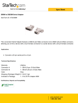
power supply, and data and signal interfaces must be connected. The overall system is represented in Figure 2.Abrief
description of each section follows.
Figure 2 MiLLennium System Functional Diagram
1
2
3
5
6
7
8
9
10
11
12
13
14 15
16
18
17
19
19
20
21
22
23
4
Reference Description Reference Description
1 MiLLennium L1/L2 GPSCard 13 VCTCXO
2 RF section 14 RF-IF sections
3 Digital section 15 Signal processor
4 NovAtel GPSAntenna or user-supplied 16 32-bit CPU
5 Optional user-supplied LNA power (0-30 VDC) 17 System I/O
6 User-supplied power (5 VDC) 18 LNA
7 Optional external oscillator (5 or 10 MHz) 19 Clock signals
8 User-supplied data & signal processing equipment 20 AGC signals
9 COM1 21 Control signals
10 COM2 22 RF and power connectors
11 Input timing strobe 23 Antenna feed
12 Output timing strobe

2 Hardware Configuration
14 MiLLennium GPSCard and Enclosures Guide to Installation & Operation
ANTENNA
The purpose of the antenna is to convert the electromagnetic waves transmitted by the GPS satellites into RF signals. An
active GPS antenna is required; a hardware provision is provided to select an internal or external DC power supply for the
active GPS antenna.
An active antenna is required because its low-noise amplifier (LNA) boosts the power of the incoming signals to
compensate for the line loss between the antenna and MiLLennium. The allowable cable loss for an active antenna
system is 13.0 dB. Excessive signal degradation will occur if this limit is exceeded and the MiLLennium may not be able
to meet its performance specifications.
NovAtel offers a variety of GPSAntenna models. All use low-profile microstrip technology and include band-pass
filtering and an LNA. The GPSAntenna you choose will depend on your particular application and hardware
configuration:
L1-Only Antenna Models
•
501 - for surveying applications providing enhanced multipath rejection
•
511 - compact, light and environmentally sealed against rain, ice and lightning strikes
•
521 - delivers optimal performance for airborne, marine and mobile applications
•
531 - for surveying and other kinematic positioning applications
L1/L2 Antenna Models
•
502 - for use in surveying and other kinematic positioning applications (an optional choke-ring ground plane,
NovAtel part number A032, is also available for use with this model)
•
503 - for use with high-performance position-reference stations (features a built-in choke-ring ground plane to
minimize the effects of multipath interference)
•
512 - for installation on aircraft (features aerodynamic styling)
Each of these models offers exceptional phase-center stability as well as a significant measure of immunity against
multipath interference. Each one has an environmentally sealed radome.
NovAtel also offers high-quality coaxial cable in standard 5, 15 and 30 m lengths. High quality coaxial cable should be
used because a mismatch in impedance, possible with lower quality cable, produces reflections in the cable that increases
signal loss.
While there may be other coaxial cables and antennas on the market that may also serve the purpose, please note that the
performance specifications of the MiLLennium are guaranteed only when it is used with NovAtel-supplied accessories.
ANTENNA CONSIDERATIONS
Selecting and installing an appropriate antenna system are important steps to make before operating your GPS receiver.
The antenna you choose for your GPS system will depend on the specific positioning application.
The choke-ring ground plane on the GPSAntenna Model 503 will further reduce multipath errors while maintaining a
stable phase center (e.g. during geodetic survey-quality positioning). An optional choke-ring (Model A032) is also
available for GPSAntenna Model 502.
The MiLLennium has been designed to operate with any of the NovAtel GPSAntenna models. Though it is possible to
operate with other GPS antennas, no guarantee is made that the MiLLennium will meet its performance specifications if a
non-NovAtel antenna is used.
When installing the antenna system,
• choose an antenna location that has a clear view of the sky to the horizon so that each satellite above the horizon can
be tracked without obstruction
• the location should also be one that minimizes the effect of multipath. For a discussion on multipath, please refer to
the chapter on “Multipath Elimination Technology” in the MiLLennium Command Descriptions Manual

2 Hardware Configuration
MiLLennium GPSCard and Enclosures Guide to Installation & Operation 15
•
mount the antenna on a secure, stable structure capable of safe operation in the specific environment
ANTENNA CABLE CONSIDERATIONS
An appropriate coaxial cable is one that is matched to the impedance of antenna being used, and whose line loss does not
exceed the recommendation of 13 dB. High quality coaxial cable should be used because a mismatch in impedance,
possible with lower quality cable, produces reflections in the cable that increases signal loss. NovAtel offers a variety of
coaxial cables to meet your GPSAntenna interconnection requirements. Your local NovAtel dealer can advise you about
your specific configuration.
NovAtel provides optional coaxial cables in the following lengths:
•
22 cm interconnect adapter cable (SMB female/TNC bulkhead - female)
•
5 m (Model C005), 15 m (Model C015), or 30 m (Model C030) antenna cable (TNC male/TNC male)
Should your application require the use of cable longer than 30 m, contact the NovAtel Customer Service department and
request Application Note APN-003, “Extended-Length Antenna Cable Runs” before you proceed. Application notes may
also be found on the NovAtel website at http://www.novatel.ca.
Any of the GPSAntennas can compensate for up to 13 dB of cable loss; if this limit is exceeded, excessive signal
degradation will occur and the MiLLennium may not be able to meet its performance specifications.
Though it is possible to use other high-quality antenna cables, no guarantee is made that the MiLLennium will meet its
performance specifications if non-NovAtel-supplied coaxial cable is used.
Note: The coaxial cable should be connected to the antenna and MiLLennium before system power is turned on. If
for any reason the cable is disconnected from the antenna or MiLLennium, you must turn off power before
reconnecting the cable. This is to prevent the MiLLennium’s antenna current-limiting circuit from
unnecessarily activating and shutting off power to the GPSAntenna. If this occurs, remove power from the
MiLLennium, wait a few moments, and then apply it again.
PRINCIPAL POWER SUPPLY
A single external 5 V DC power supply is all that is necessary to meet the MiLLennium’s 7.5 W (typical) power
consumption. The power input is reverse-polarity protected.
Note: The MiLLennium will suspend operation if the voltage supplied to it falls outside the input range of 4.875 to 5.25 V DC.
OPTIONAL LNA POWER SUPPLY
The MiLLennium provides power to its GPSAntenna out of the primary 5 V DC input. However, if a different type of
antenna is required that is incompatible with this supply, then you could connect an additional power source (
≤
30 V DC)
to the MiLLennium. In either case, the power is fed to the antenna through the same coaxial cable used for the RF
signals. See jumper P301 in Chapter 3, I, Figure 3 (Page 18) and Figure 4 (Page 21).
RF SECTION
The MiLLennium receives the partially filtered and amplified GPS signals from the antenna via the coaxial cable. The
RF section does the following:
• filters the RF signals to reduce noise and interference
• down-converts (with further band-limiting) the RF signals to intermediate frequencies (IFs) that are suitable for the
analog-to-digital (A/D) converter in the digital electronics section
• amplifies the signals to a level suitable for the A/D converter in the digital electronics section
• receives an automatic gain control (AGC) input from the digital signal processor (DSP) to maintain the IF signals at
a constant level

2 Hardware Configuration
16 MiLLennium GPSCard and Enclosures Guide to Installation & Operation
•
supplies power to an active antenna through the coaxial cable while maintaining isolation between the DC and RF
paths. A hardware jumper configuration is provided to select an internal or external DC power supply for an active
GPS antenna. See jumper P301 in the Chapter 3, I, Figure 3 (on page 18) and Figure 4 (on page 21).
The RF section can reject a high level of potential interference (e.g., MSAT, Inmarsat, cellular phone, and TV sub-
harmonic signals).
DIGITAL ELECTRONICS SECTION
The digital section of the MiLLennium receives down-converted, amplified GPS signals that it digitizes and processes to
obtain a GPS solution (position, speed, direction and time). The digital section consists of an analog-to-digital converter,
a 32-bit 25 MHz system processor, memory, control and configuration logic, signal processing circuitry, serial peripheral
devices, and supporting circuitry. I/O data and timing strobe signals are routed to and from the board via a 64-pin DIN
41612 Type B male connector. Two EIA RS-232C serial communications ports support user-selectable bit rates of 300 -
115,200 bps, with a default of 9600 bps. The digital section does the following:
•
converts the IF analog signals to a digital format
•
tracks the codes (C/A & P) and carrier phases of the L1 signals (and L2 signals with the appropriate MiLLennium
model) of the satellites in use
•
performs channel and loop control
•
performs position computation
•
executes navigation software
•
performs database management
•
monitors self-test system status
•
controls diagnostic LEDs: a red one which only lights up to indicate an error condition, and a green one (the
“heartbeat”) which blinks on and off at approximately 1 Hz to indicate normal operation.
•
controls I/O functions
The strobe signals are described as follows:
•
Mark input: this signal provides a time tag to the signal processors, which respond to a falling edge of the signal
provided from an external device. It can be enabled by you to provide a precise time and data output event.
•
Measure output: an output measurement rate which generates an active-periodic signal. This output is also routed to
the signal processors, where it provides a trigger for the measurement collection.
•
Variable-frequency (VARF) output: a user-programmable, variable-frequency pulse train
•
PPS output: a 1 ms pulse repeating at a 1 Hz rate that is used to synchronize the board with external devices.
•
Status output: an output that changes logic states when a valid GPS position is obtained
You configure the MiLLennium using special commands. In turn, the MiLLennium presents information to you in the
form of pre-defined logs in a number of formats. In addition, when two MiLLenniums are linked for differential
positioning, the reference and the remote stations can communicate directly through their serial ports.
COMMUNICATION PORTS
The default communications protocol for each port is as follows:
• RS232C
• 9600 bits per second
• no parity
• 8 bits
• 1 stop bit
• no hand shaking
• echo off

2 Hardware Configuration
MiLLennium GPSCard and Enclosures Guide to Installation & Operation 17
Note: The GPSCard COMn command can be used to change any of these default settings.
Pin-outs are the same for both serial ports. Both ports utilize standard DE9P connectors. Table 6 Serial Port Pin-Out
Description, Page 50 lists the pin-outs for each serial port configuration.
OPTIONAL USER-SUPPLIED EXTERNAL OSCILLATOR
For certain applications requiring greater precision than what is possible using the on-board 20 MHz, voltage-controlled,
temperature-compensated crystal oscillator (VCTCXO), you may wish to connect the MiLLennium to an external, high-
stability oscillator. This is only possible with a MiLLennium GPSCard on its own or in a PowerPak II enclosure, not if
the MiLLennium GPSCard is in a ProPak II enclosure. The external oscillator can be either 5 MHz or 10 MHz.
MiLLennium has built in clock models for OCXO, rubidium and cesium oscillators. You can also set custom clock model
parameters for other types of oscillators.
The two commands EXTERNALCLOCK and EXTERNALCLOCK FREQUENCY relate to external oscillator
operation, see the Using the EXTERNALCLOCK Commands section below. When a MiLLennium is powered on, the
external oscillator input is disabled. Therefore, if an external oscillator is never used, these commands are not needed.
Installation consists of simply connecting the cable from the external oscillator to connector P301, see Figure 3 (Page 18)
and Figure 4 (Page 21), on the MiLLennium. The MiLLennium does not have to be powered down during this
procedure. If handling the MiLLennium directly, anti-static practices must be observed; please see Appendix A (Page 31)
for details.
On the PowerPak II, connect the coaxial cable from the external oscillator output port to the Ext. Osc. input port (SMB
male jack) on the front panel of the PowerPak II.
Using the EXTERNALCLOCK Commands
The EXTERNALCLOCK command determines whether the MiLLennium uses its own internal temperature-
compensated crystal oscillator, or that of an external oscillator, as a frequency reference. It also sets which clock model is
used for an external oscillator:
Command Reference Oscillator Clock Model
EXTERNALCLOCK DISABLE Internal
EXTERNALCLOCK OCXO External OCXO
EXTERNALCLOCK CESIUM External Cesium
EXTERNALCLOCK RUBIDIUM External Rubidium
EXTERNALCLOCK CUSTOM External User-defined parameters
The EXTERNALCLOCK DISABLE command forces the MiLLennium to use the internal oscillator, whether or not
there is an external oscillator connected to it. Do not use the EXTERNALCLOCK OCXO, CESIUM, RUBIDIUM or
CUSTOM if there is no external oscillator connected to the MiLLennium.
The EXTERNALCLOCK FREQUENCY command sets the MiLLennium to accept either a 5 MHz or 10 MHz external
oscillator frequency.
Example: externalclock frequency 5
externalclock frequency 10

3 Installation
18 MiLLennium GPSCard and Enclosures Guide to Installation & Operation
3 INSTALLATI ON
3 INSTALLATION
Note: This chapter deals specifically with a bare MiLLennium receiver card. For MiLLenium cards in PowerPak II
and ProPak II enclosures, see Appendices C and D respectively.
The MiLLennium receiver is an OEM product designed for flexibility of integration and configuration. You are free to
select an appropriate data and signal interface, power supply system, and mounting structure. This concept allows OEM
purchasers to custom-design their own GPS-based positioning system around the MiLLennium.
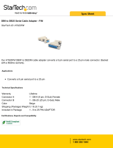
This section provides the necessary information for you to install and begin to use the MiLLennium. A typical system
configuration is shown in Figure 3.
Figure 3 Typical System Configuration
Reference Description Reference Description
1 User-supplied enclosure 9 COM1 (8 pins)
2 RF signal and LNA power; SMB 10 COM2 (8 pins)
connector P201 (male, right-angle)* 11 Input and output timing strobes (12 pins)x
3 External reference clock input; SMB 12 User-supplied interface; matches item #4
connector P301 (male, straight) 13 Model 502 GPSAntenna (L1/L2)
4 Power, data & signals connector P1 (male, 14 Model 503 GPSAntenna (L1/L2)
64-pin, 0.1”, DIN 41612, Type B, right-angle) 15 Model 512 GPSAntenna (L1/L2)
5 Status LEDs (green and red) 16 Model 501 GPSAntenna (L1 Only)
6 LNA power jumper P301 (see
Figure 4, Page 21
) 17 Model 511 GPSAntenna (L1 Only)
7 +5 V DC primary power (2 pins) 18 Model 521 GPSAntenna (L1 Only)
8 Optional LNA; DC power (1 pin) 19 Model 531 GPSAntenna (L1 Only)
* To antenna via interconnecting coaxial cable. High quality coaxial cable should be used because a mismatch in
impedance, possible with lower quality cable, produces reflections in the cable that increases signal loss.
7
8
9
10
11
12
5
1
2
6
3
4
13
14
15
16
17
18
19

3 Installation
MiLLennium GPSCard and Enclosures Guide to Installation & Operation 19
MINIMUM CONFIGURATION
In order for the MiLLennium to perform optimally, the following additional equipment is required:
•
NovAtel GPSAntenna (model will depend on application)
•
NovAtel coaxial cable (note that a conversion is required between the male SMB connector on the MiLLennium and
the female TNC connector on a GPSAntenna)
•
A regulated power supply providing +5 V DC (see Appendix B, Page 33) for power regulation specifications)
•
A 64-pin 0.1" DIN 41612 Type B female connector as an interface for power, communications and signals
•
Data communications equipment capable of RS-232C serial communications
ANTI-STATIC PRECAUTIONS
Electrostatic discharge (ESD) is a leading cause of failure of electronic equipment components and printed circuit boards
containing ESD-sensitive devices and components. It is imperative that ESD precautions be followed when handling or
installing the MiLLennium printed circuit board. See Appendix A, Page 31 for more information on ESD precautions.
Leave the MiLLennium in its anti-static packaging when not connected in its normal operating environment. When
removing the MiLLennium from the ESD-protective plastic clamshell, follow accepted standard anti-static practices.
Failure to do so may cause damage to the MiLLennium.
When you remove the MiLLennium from the original packing box, it is recommended that you save the box and ESD
protective plastic clamshell for future storage or shipment purposes.
REMEMBER !
•
Always wear a properly grounded anti-static wrist strap when handling the MiLLennium.
•
Always hold the MiLLennium by its corners or the RF backplane, and avoid direct contact with any of the
components.
•
Do not let the MiLLennium come in contact with clothing at any time because the grounding strap cannot dissipate
static charges from fabrics.
•
Failure to follow accepted ESD handling practices could cause damage to the MiLLennium.
•
Warranty may be voided if equipment is damaged by ESD.
INSTALLATION PROCEDURE
Installing the MiLLennium typically consists of the following:
1. mounting the MiLLennium in a secure enclosure to reduce environmental exposure, RF interference, and vibration
effects
2. pre-wiring the I/O harness and the 64-pin DIN female connector for power and communications, then connecting
them to the MiLLennium
3. installing the GPSAntenna, then connecting it to the MiLLennium (see Page 14)
4. installing an optional external oscillator (see Page 17)
MOUNTING THE PRINTED CIRCUIT BOARD
Because the MiLLennium is an OEM product, the printed circuit board is not enclosed in a housing structure. This
allows flexibility in creating a mounting environment to suit particular product and marketing requirements. The
mounting and enclosure must provide the following:
• mounting of external connectors

3 Installation
20 MiLLennium GPSCard and Enclosures Guide to Installation & Operation
•
protection from hostile physical environments (e.g. rain, snow, sand, salt, water, extreme temperatures)
•
protection from vibration conditions
•
electromagnetic shielding to protect from hostile RF environments (e.g. nearby transmitters)
•
electromagnetic shielding so that the final product itself conforms to RF emissions guidelines
•
protection from ESD
The MiLLennium card can be held in place by screws, card rails, or both. Please see Appendix B, Page 33 for
mechanical drawings.
PREPARING THE DATA, SIGNAL & POWER HARNESS
The wiring harness provides the following interconnect functions:
•
access to COM1 and COM2 serial communications ports
•
access to input and output timing strobes
•
power input(s)
•
access to control signals
A 64-pin / 0.1" / DIN 41612 / Type B / female connector (e.g. Harting #0902 164 6825, #0902 264 6828, or equivalent)
is required to interface with connector P1 on the MiLLennium (see Figure 3 Typical System Configuration, Page 18).
The connectors you choose for interfacing to the power source(s), COM ports, and strobes will depend on your external
equipment requirements. Appendix E, EDGE-VIEW OF CONNECTOR P1, Page 65 shows the pin names and locations
on connector P1.
Note: See Appendix B, MILLENNIUM TECHNICAL , Page 33 for descriptions of the function of each connector
pin.
A MiLLennium GPSCard can function with the same 64-pin connector built for an OEM2 GPSCard (NovAtel’s second
generation receiver), which makes the upgrade simple. However, an OEM2 GPSCard will not function with a connector
built for a MiLLennium; this is because several pins on the OEM2 GPSCard are no longer used on the MiLLennium, as
shown in Table 2:
Table 2 Disabled OEM2 Connector Pins
OEM2 Signal Name Connector Pin
-12VDC 3A
+12VDC 3B
SELA1 5 B
SELB1 6 B
NMEA Opto 1 7 B
TXD1(-)/NULL 8 B
SELA2 13 B
SELB2 14 B
NMEA Opto 2 15 B
TXD2(-)/NULL 16 B
External Power
See Appendix B, Page 33 for external power input connections:
• Digital ground
pins 1A/B (internally connected)
• Vcc, main power (+5 V DC)
pins 2A/B (internally connected)
• Optional external LNA power
pin 4B (≤ 30 V DC) and 4A (GND)
/