Microsemi SmartFusion2 MSS is a powerful and versatile system-on-a-chip (SoC) FPGA that combines the processing power of an ARM Cortex-M3 microcontroller with the flexibility of a programmable FPGA fabric. With its high-performance architecture, SmartFusion2 MSS enables the implementation of complex designs that require both processing and logic capabilities.
This device is ideal for a wide range of applications, including industrial automation, automotive systems, medical devices, and consumer electronics. Its features include:
- High-performance ARM Cortex-M3 microcontroller with DSP instructions


-
 1
1
-
 2
2
-
 3
3
-
 4
4
-
 5
5
-
 6
6
-
 7
7
-
 8
8
-
 9
9
-
 10
10
-
 11
11
-
 12
12
-
 13
13
-
 14
14
-
 15
15
-
 16
16
-
 17
17
-
 18
18
-
 19
19
-
 20
20
-
 21
21
-
 22
22
-
 23
23
-
 24
24
-
 25
25
-
 26
26
-
 27
27
-
 28
28
-
 29
29
-
 30
30
-
 31
31
-
 32
32


Microsemi SmartFusion2 MSS User guide
- Type
- User guide
- This manual is also suitable for
Microsemi SmartFusion2 MSS is a powerful and versatile system-on-a-chip (SoC) FPGA that combines the processing power of an ARM Cortex-M3 microcontroller with the flexibility of a programmable FPGA fabric. With its high-performance architecture, SmartFusion2 MSS enables the implementation of complex designs that require both processing and logic capabilities.
This device is ideal for a wide range of applications, including industrial automation, automotive systems, medical devices, and consumer electronics. Its features include:
- High-performance ARM Cortex-M3 microcontroller with DSP instructions
Ask a question and I''ll find the answer in the document
Finding information in a document is now easier with AI
Related papers
-
Microsemi FlashPro Lite Quick Start Card
-
-
-
Microsemi SmartFusion2 MSS Reset Controller User manual
-
Microsemi SmartFusion2 MSS Demo Manual
-
-
-
-
-
Microsemi SmartDesign MSS Canvas User guide
Other documents
-
Microchip Technology Microsemi Hello FPGA Libero Design User manual
-
 Wolverine 8000 User manual
-
RAM LMS266 DSP User manual
-
-
Electrolux VARIOL1 Datasheet
-
 Actel FlashPro4 Quick Start Card
-
-
Adaptec RAID 81605ZQ with maxCache Installation guide
-
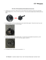 Newport FP4-COL-1550 Operating instructions
-


