Tripp Lite IBAR12/20ULTRA Owner's manual
- Category
- Power distribution units (PDUs)
- Type
- Owner's manual
This manual is also suitable for

Owner’s Manual
Rackmount Power Strips and Isobar
®
Rackmount Surge Suppressors/
Line-Noise Filters
Designed to Occupy One Standard 19 in. Rack Space
IMPORTANT SAFETY INSTRUCTIONS. This manual contains information concerning the proper installation
and use of Tripp Lite’s Rackmount Power Strips and Isobar Surge Suppressors. SAVE THESE INSTRUCTIONS.
(IBAR12, ISOBAR12ULTRA, RS-1215, RS-1215-RA, RS-1215-HG, DRS-1215):
DO NOT exceed the MAXIMUM LOAD of 15 amps that can be drawn from
each AC outlet. DO NOT exceed the MAXIMUM LOAD of 15 amps that can be
drawn from all the outlets combined.
(IBAR12/20ULTRA, IBAR12-20T, RS-1215-20): DO NOT exceed the MAXIMUM LOAD of 15
amps that can be drawn from each AC outlet located on the front of the IBAR12/20ULTRA
and IBAR12-20T. DO NOT exceed the MAXIMUM LOAD of 20 amps that can be drawn from
each AC outlet on the RS-1215-20, or each AC outlet located on the rear of the
IBAR12/20ULTRA and IBAR12-20T. DO NOT exceed the MAXIMUM LOAD of 20 amps that
can be drawn from all the outlets combined.
Español: p. 5 • Français: p. 9
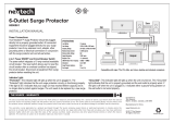
Rackmount Installation
To Mount Unit in Rack: Put four user-supplied rackmount
screws (A) through the unit’s mounting ears (B) and into
the rack rails as shown. The user must determine the fitness
of the rackmount screws to hold the unit in the rack before
installation.
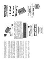
Wallmount/Under Counter Installation
1. Detach Mounting Ears: Unscrew the screws (A) holding
the unit’s mounting ears (B) to the sides of the unit.
2. Reorient Mounting Ears: Use the screws from Step 1 (A)
to reattach the mounting ears (B) to the unit as shown.
Use only the manufacturer-supplied screws or their
equivalent (#6-32, ¼" flat head) to reattach the mounting
ears. The screws should be put through diagonally
opposite holes on the ear.
3. Mount Unit on Surface: Put four user-supplied screws
(C) or similar mounting hardware through the unit’s
mounting ears (B) and into the mounting surface as
shown. The user must determine the fitness of the user-
supplied mounting hardware to support the unit before
mounting.
Devices with surge protection feature an internal protection that will disconnect the surge protective
component at the end of its useful life but will maintain power to the load—now unprotected.
Step 1
Steps 2 & 3
200307176 Isobar RM Metal Owner’s Manual 93-2134.qxd 8/4/2003 11:10 AM Page 1

32
Features
Circuit Breaker (All Models)
If the current draw of the equipment connected to your model exceeds your model’s circuit breaker rating
(15 or 20 amps; see Specifications) for longer than a few seconds, the circuit breaker will trip to prevent
any possible damage. When the circuit breaker trips, its plunger will be extended. Remove excess equipment
and allow the breaker to cool one minute before depressing its plunger to reset the breaker.
Illuminated “On/Off” Switch (All Models)
When your model is plugged into an AC outlet providing power of appropriate voltage and frequency (see
specifications), this switch will illuminate RED when moved to the “ON” position. This indicates 120V AC
power is present at the model’s AC receptacles.
Diagnostic Indicator Lights (ISOBAR Models Only)
When your surge suppressor is plugged into an AC outlet providing power of appropriate voltage and frequency
(see Specifications), the three LEDs on the front panel show current power conditions as follows, from left
to right across the front of the unit:
Line “OK” (Green LED): Indicates that nominal AC power is present with no wiring faults detected.
When this LED is illuminated, AC power is safe for connected equipment.
Line Fault (Red LED): Indicates a wiring fault has been detected. If this LED illuminates at any time
the unit is plugged in, the fault should be repaired by a qualified electrician as soon as possible. This
LED indicates that phases are reversed, ground is missing or some other sort of wiring error exists in the
circuit the ISOBAR is plugged into. The Line Fault detector circuitry will identify most common wiring
faults, but will not necessarily detect every possible type of fault.
If the Line Fault indicator light illuminates, carefully check the AC receptacle the ISOBAR
is plugged into. The receptacle must be tight and securely grounded. A loose AC
receptacle may cause the Line Fault LED to illuminate. It must be understood that
this Red LED indicates the presence of a wiring fault, but does not indicate the
exact nature of the fault.Therefore, a qualified electrician should make necessary repairs.
If the Line Fault indicator light illuminates and power is not present at the outlets,
the ISOBAR’s surge-suppression components have been compromised as a result
of surge damage. For service, call Tripp Lite Customer Support at (773) 869-1234.
Fully explain the perceived problem to the customer support person. They will
either remedy the problem over the phone or give you instructions about return,
repair or exchange.
Protection Present (Green LED): Indicates the surge-suppression components are intact and providing
full protection against spikes and surges. This LED should be lit anytime the ISOBAR “ON/OFF”
switch is turned ON and power is present, as indicated by the lighted power switch. If the Protection
Present LED does not light, then some of the surge suppression components are not functioning and the
unit should be returned for repair as soon as possible. You may still use the unit; however, connected
equipment will be protected from spikes and surges at a lesser level than normal.
ISOLATED FILTER BANKS & CASCADE CIRCUITRY
(IBAR12 and ISOBAR12ULTRA Models Only)
Isolated Filter Banks prevent equipment plugged into each filter bank from interacting with equipment
plugged into the other filter bank. Cascade Circuitry provides different levels of protection between the
Isolated Filter Banks.
There are two Isolated Filter Banks on IBAR12 and ISOBAR12ULTRA models. Isolated Filter Bank #2,
the white outlets on these models’ rear panel, provides the highest level of protection for your most sensitive
equipment. Isolated Filter Bank #1, the black outlets on these models’ front and rear panels, provides
standard protection for your less-sensitive or noise-producing equipment.
Specifications
Model: IBAR12 ISOBAR12ULTRA IBAR12/20ULTRA
Series: AGIB120V12SSRM AGIB120V12SSRM AGIB120V20SSRM
AC Energy Absorption (joules): 1280 1280 1280
Surge Suppression (amp spikes)*: 60,000 96,000 96,000
UL 1449 Let-Through Rating: 400V 330V 330V
HF Noise Suppression (@ 1 MHz)
Filter Bank #1: 40 dB 40 dB 80 dB
Filter Bank #2: 80 dB 80 dB —
AC Receptacles: 2 NEMA 5-15R (front) 2 NEMA 5-15R (front) 2 NEMA 5-15R (front)
10 NEMA 5-15R (back) 10 NEMA 5-15R (back) 10 NEMA 5-15/20R (back)
AC Line Cord: 15', w/NEMA 5-15P plug 15', w/NEMA 5-15P plug 15', w/NEMA 5-20P plug
Circuit Breaker (Resettable): 15 amp 15 amp 20 amp
Dimensions (HxWxD, inches): 1.7 × 17.3 × 3.4 1.7 × 17.3 × 3.4 1.7 × 17.3 × 3.4
Weight (lbs.): 4.6 5.0 5.4
Model: IBAR12-20T RS-1215 RS-1215-20
Series: AGIB120V20SSRM AGIP120V6IPRM AGIP120V20RM
AC Energy Absorption (joules): 1280 NONE NONE
Surge Suppression (amp spikes): 96,000 NONE NONE
UL 1449 Let-Through Rating: 330V — —
HF Noise Suppression (@ 1 MHz)
Filter Bank #1: 80 dB NONE NONE
Filter Bank #2: — NONE NONE
AC Receptacles: 2 NEMA 5-15R (front) 6 NEMA 5-15R (front) 6 NEMA 5-20R (front)
10 NEMA 5-15/20R (back) 6 NEMA 5-15R (back) 6 NEMA 5-20R (back)
AC Line Cord: 15', w/L5-20P plug 15', w/NEMA 5-15P plug 15', w/NEMA 5-20P plug
Circuit Breaker (Resettable): 20 amp 15 amp 20 amp
Dimensions (HxWxD, inches): 1.7 × 17.3 × 3.4 1.7 × 17.3 × 3.4 1.7 × 17.3 × 3.4
Weight (lbs.): 5.4 4.6 4.6
Model: RS-1215-RA RS-1215-HG DRS-1215
Series: AGIP120V6IPRM AGIP120V6IPRM AGIB120V12LCRM
AC Energy Absorption (joules): NONE NONE 1050
Surge Suppression (amp spikes): NONE NONE 36,000
UL 1449 Let-Through Rating: — — 330V
HF Noise Suppression (@ 1 MHz)
Filter Bank #1: NONE NONE NONE
Filter Bank #2: NONE NONE NONE
AC Receptacles:
6 NEMA 5-15R (front) 6 15A hospital grade (front) 6 NEMA 5-15R (front)
6 NEMA 5-15R (back) 6 15A hospital grade (back) 6 NEMA 5-15R (back)
AC Line Cord: 15', w/NEMA 5-15P plug 15', w/15A hospital grade plug 15', w/NEMA 5-15P plug
Circuit Breaker (Resettable): 15 amp 15 amp 15 amp
Dimensions (HxWxD, inches): 1.7 × 17.3 × 3.4 1.7 × 17.3 × 3.4 1.7 × 17.3 × 4
Weight (lbs.): 4.6 4.6 4.6
* Spike protection is provided in all three modes: hot to neutral, hot to ground and neutral to ground.
All Models: Nominal Input Voltage: 120VAC; Input Frequency: 50/60 Hz
All ISOBAR Models: Transient Response Time: Instantaneous (0 ns). Transient amplitude reduction occurs faster than
the clamp response of the varistors because of the high rejection rate of the ISOBAR filter networks.
UL 1449 (1999 rev.): ISOBAR12ULTRA, IBAR12/20ULTRA, IBAR12-20T and DRS-1215:
330V let-through (UL’s best rating for surge suppression); IBAR12: 400V let-through
UL 1283: All ISOBAR models, for line-noise filtering
CUL: meets Canadian National Standards as certified by UL
200307176 Isobar RM Metal Owner’s Manual 93-2134.qxd 8/4/2003 11:10 AM Page 2

54
Seller warrants this product, if used in accordance with all applicable instructions, to be free from original defects in material and
workmanship for its lifetime. If the product should prove defective in material or workmanship within that period, Seller will repair
or replace the product, in its sole discretion. Service under this warranty can only be obtained by your delivering or shipping the
product (with all shipping or delivery charges prepaid) to: Tripp Lite, 1111 W. 35th Street, Chicago, IL 60609. Seller will pay return
shipping charges. Call Tripp Lite at (773) 869-1234 before sending any equipment back for repair.
The warranties of all TRIPP LITE surge suppressors are null and void if they have been connected to the output of any UPS system.
The warranties of all TRIPP LITE UPS Systems are null and void if a surge suppressor has been connected to its output receptacles.
THIS WARRANTY DOES NOT APPLY TO NORMAL WEAR OR TO DAMAGE RESULTING FROM ACCIDENT, MISUSE, ABUSE
OR NEGLECT. SELLER MAKES NO EXPRESS WARRANTIES OTHER THAN THE WARRANTY EXPRESSLY SET FORTH
HEREIN. EXCEPT TO THE EXTEND PROHIBITED BY APPLICABLE LAW, ALL IMPLIED WARRANTIES, INCLUDING ALL
WARRANTIES OF MERCHANTABILITY OR FITNESS, ARE LIMITED IN DURATION TO THE WARRANTY PERIOD SET FORTH
ABOVE; AND THIS WARRANTY EXPRESSLY EXCLUDES ALL INCIDENTAL AND CONSEQUENTIAL DAMAGES. (Some
states do not allow limitations on how long an implied warranty lasts, and some states do not allow the exclusion or limitation of
incidental or consequential damages, so the above limitations or exclusions may not apply to you. This Warranty gives you specific
legal rights, and you may have other rights which vary from jurisdiction to jurisdiction).
WARNING: The individual user should take care to determine prior to use whether this device is suitable, adequate
or safe for the use intended. Since individual applications are subject to great variation, the manufacturer makes no
representation or warranty as to the suitability or fitness of these devices for any specific application.
Policy of Tripp Lite is one of continuous improvement. Specifications are subject to change without notice.
(Applicable Only to ISOBAR Models. Valid in U.S. and Canada Only)
TRIPP LITE warrants, for the lifetime of the product, (at TRIPP LITE’S option) to repair or replace (on a pro rata basis) directly
connected equipment, that is damaged due to power transients while properly connected to TRIPP LITE products offering the
ULTIMATE Lifetime Insurance Policy. Reimbursement or restoration for data loss is not included. Power transients include spikes
and surges on the AC power, data, or telephone lines that the TRIPP LITE products have been designed to protect against (as
recognized by industry standards).
AC Power Line Transients: To claim damages the TRIPP LITE product must be plugged into a properly wired and grounded outlet.
No extension cords, or other electrical connections may be used. The installation must comply with all applicable electrical and
safety codes set forth by the National Electrical Code (NEC). Except as provided above, this warranty does not cover any damage to
properly connected electronic equipment resulting from a cause other than an “AC power transient”. If user meets all of the above
requirements, TRIPP LITE will repair or replace (at TRIPP LITE’S option) equipment up to the specified value (See ULTIMATE
Lifetime Insurance Policy Limits). No coverage is allowed for damage entering from telephone or data lines, unless they are
separately protected as described below.
Reimbursement dollar limits will be equal to that of the Tripp Lite power protection protector. Coverage is excluded where a suitable
environment for the protection device is not provided, including, but not limited to, lack of a proper safety ground. Telephone service
equipment must also include a properly installed and operating “primary protection” device at the telephone service entrance
(such devices are normally added during telephone-line installation).
All above warranties are null and void if the TRIPP LITE product has been improperly installed, tampered with or altered in any
way, or if the connected equipment was not used under normal operating conditions or in accordance with any labels or instructions.
All claims under this warranty must be submitted in writing to Tripp Lite within 30 days of the occurrence or the claim will not be
considered. This warranty does not include damage resulting from accident or misuse, and applies to the domestic (USA &
Canada) use of these products only.
Tripp Lite reserves the right to determine whether the damage to the connected equipment is due to malfunction of the Tripp Lite
product by requesting the equipment in question be sent to Tripp Lite for examination. This policy is above and beyond, only to
the extent needed, of that provided by any coverage of connected equipment provided by other sources, including, but not limitedto,
any manufacturer’s warranty and/or any extended warranties.
EXCEPT AS PROVIDED ABOVE, TRIPP LITE MAKES NO WARRANTIES, EXPRESS OR IMPLIED, INCLUDING WARRANTIES
OF MERCHANTABILITY AND FITNESS FOR A PARTICULAR PURPOSE. Some states do not permit limitation or exclusion of
implied warranties; therefore, the aforesaid limitation(s) or exclusion(s) may not apply to purchaser.
EXCEPT AS PROVIDED ABOVE, IN NO EVENT WILL TRIPP LITE BE LIABLE FOR DIRECT, INDIRECT, SPECIAL, INCIDENTAL,
OR CONSEQUENTIAL DAMAGES ARISING OUT OF THE USE OF THIS PRODUCT, EVEN IF ADVISED OF THE POSSIBILITY
OF SUCH DAMAGE. Specifically, TRIPP LITE is not liable for any costs, such as lost profits or revenue, loss of equipment, loss
of use of equipment, loss of software, loss of data, costs of substitutes, claims by third parties, or otherwise.
To receive service under this warranty, you must be the original purchaser/user of the product in question. You must obtain a
Returned Material Authorization (RMA) number from TRIPP LITE. Products must be returned to TRIPP LITE with transportation
charges prepaid and must be accompanied by a brief description of the problem encountered and proof of date and place of purchase.
Limited Lifetime Warranty
Ultimate Lifetime Insurance Policy
Manual de
Operación
Barras de Contacto para Montaje en Bastidor y
Supresores de Sobretensiones de Isobaras para
Montaje en Bastidor Isobar
®
/Filtros de Ruido en Línea
Diseñados para ocupar un espacio estándar de bastidor de 19 pulgadas
INSTRUCCIONES DE SEGURIDAD IMPORTANTES. Este manual contiene información concerniente
a la instalación y uso apropiado de la barra de contactos para montaje en bastidor o rack y los supresores
de sobretensiones de isobaras de Tripp Lite. GUARDE ESTAS INSTRUCCIONES.
(IBAR12, ISOBAR12ULTRA, RS-1215, RS-1215-RA, R-S1215-HG, DRS-1215):
NUNCA exceda la CARGA MÁXIMA de 15 amperios que puede
obtenerse de cada contacto de CA. NUNCA exceda la CARGA MÁXIMA
de 15 amperios que puede obtenerse de los contactos combinados.
(IBAR12/20ULTRA, IBAR12-20T, RS-1215-20): NUNCA exceda la CARGA MÁXIMA de
15 amperios que puede obtenerse de cada contacto de CA localizado al frente de
la IBAR12/20ULTRA y IBAR12-20T. NUNCA exceda la CARGA MÁXIMA de 20 ampe-
rios que puede obtenerse de cada contacto de CA localizado en la RS-1215-20 o en
la parte posterior de la IBAR12/20ULTRA y IBAR12-20T. NUNCA exceda la CARGA
MÁXIMA de 20 amperios que puede obtenerse de los contactos combinados.
Instalacion en Bastidor o Rack
Para montar la unidad en un bastidor: Introduzca cuatro
tornillos para montaje en bastidor (A), proporcionados
por el usuario, a través de las lengüetas de montaje (B)
y dentro de los rieles del bastidor tal como se muestra.
El usuario debe determinar si los tornillos para montaje
en bastidor son adecuados para sostener a la unidad
antes de realizar la instalación.
Montaje Sobre la Pared / Instalacion
Bajo el Mostrador
1. Separe las lengüetas de montaje: Retire los tornillos
(A) que sostienen a las lengüetas de la unidad (B) a
ambos lados de ésta.
2 Reoriente las lengüetas de montaje: Utilice los
tornillos (A) del Paso 1 para volver a unir las lengüetas
de montaje (B) a la unidad tal como se muestra.
Utilice únicamente los tornillos suministrador por el
fabricante, u otros equivalentes (#6-32, cabeza plana
de ¼"), para volver a unir las lengüetas de montaje.
Los tornillos deben colocarse a través de los orificios
diagonalmente opuestos a la lengüeta.
3. Montaje de la unidad sobre la superficie: Ponga cuatro tornillos (C), proporcionados por el usuario,
u otro equipo de montaje similar, a través de las lengüetas de montaje (B) y dentro de la superficie de
montaje tal como se muestra. El usuario debe determinar si el equipo de montaje utilizado es adecuado para
soportar la unidad antes de realizar el montaje.
Los dispositivos con proteccion de sobretensiones cuentan con proteccion interna la cual
desconectara el componente de proteccion de sobretensiones cuando este llegue al final de su vida
util sin embargo mantendran un flujo de energia hacia la carga—sin proteccion ahora.
Paso 1
Pasos 2 & 3
200307176 Isobar RM Metal Owner’s Manual 93-2134.qxd 8/4/2003 11:10 AM Page 4
-
 1
1
-
 2
2
-
 3
3


Tripp Lite IBAR12/20ULTRA Owner's manual
- Category
- Power distribution units (PDUs)
- Type
- Owner's manual
- This manual is also suitable for
Ask a question and I''ll find the answer in the document
Finding information in a document is now easier with AI
Related papers
-
Tripp Lite Rackmount Power Strips and Isobar Rackmount Surge Suppressors/ Line-Noise Filters User manual
-
Tripp Lite RS1215-RA User manual
-
-
Tripp Lite RS-1215 User manual
-
-
-
-
-
Tripp Lite TRAVELER3USB Owner's manual
-
Other documents
-
CableWholesale 50W1-905304 Datasheet
-
 VITAL 6-Outlet Power Bar User manual
-
 Minuteman UPS MMS760RCT User manual
-
Klark Teknik DW 20R Quick start guide
-
Manhattan 161138 Datasheet
-
-
 SharkRack PWS-70115 User manual
-
Black Box SP472A-R3 Datasheet
-
-


