Smeg A1-6 User manual

Category
Cookers
Type
User manual

This manual is also suitable for

Contents
1. INSTRUCTIONS FOR SAFE AND PROPER USE_______________ 36
2. INSTALLATION OF THE APPLIANCE________________________ 38
3. ADAPTATION TO DIFFERENT TYPES OF GAS _______________ 40
4. FINAL OPERATIONS_____________________________________ 42
5. DESCRIPTION OF CONTROLS ____________________________ 44
6. USE OF THE COOKING HOB ______________________________ 51
7. USE OF THE OVEN______________________________________ 52
8. AVAILABLE ACCESSORIES _______________________________ 54
9. COOKING HINTS________________________________________ 55
10. CLEANING AND MAINTENANCE ___________________________ 61
11. EXTRAORDINARY MAINTENANCE _________________________ 64
THESE INSTRUCTIONS ARE VALID ONLY FOR END USER COUNTRIES WHOSE
IDENTIFICATION SYMBOLS APPEAR ON THE COVER OF THIS MANUAL.
INSTRUCTIONS FOR THE INSTALLER: these are for the qualified
technician who must carry out a suitable check of the gas system,
install the appliance, set it functioning and carry out an inspection test.
INSTRUCTIONS FOR THE USER: these contain user advice,
description of the commands and the correct procedures for cleaning
and maintenance of the appliance.
35
Introduction
1. INSTRUCTIONS FOR SAFE AND PROPER USE
THIS MANUAL IS AN INTEGRAL PART OF THE APPLIANCE AND
THEREFORE MUST BE KEPT IN ITS ENTIRETY AND IN AN ACCESSIBLE
PLACE FOR THE WHOLE WORKING LIFE OF THE COOKER. WE ADVISE
READING THIS MANUAL AND ALL THE INSTRUCTIONS THEREIN BEFORE
USING THE COOKER. ALSO KEEP THE SERIES OF NOZZLES SUPPLIED.
INSTALLATION MUST BE CARRIED OUT BY QUALIFIED PERSONNEL IN
ACCORDANCE WITH THE REGULATIONS IN FORCE. THIS APPLIANCE IS
INTENDED FOR DOMESTIC USES AND CONFORMS TO CURRENT
REGULATIONS IN FORCE. THE APPLIANCE HAS BEEN BUILT TO CARRY
OUT THE FOLLOWING FUNCTIONS: COOKING AND HEATING-UP OF FOOD.
ALL OTHER USES ARE CONSIDERED IMPROPER.
THE MANUFACTURER DECLINES ALL RESPONSIBILITY FOR IMPROPER
USE.
DO NOT LEAVE THE PACKING IN THE HOME ENVIRONMENT. SEPARATE
THE VARIOUS WASTE MATERIALS AND TAKE THEM TO THE NEAREST
SPECIAL GARBAGE COLLECTION CENTRE.
IT IS OBLIGATORY FOR THE ELECTRICAL SYSTEM TO BE GROUNDED
ACCORDING TO THE METHODS REQUIRED BY SAFETY RULES.
THE PLUG TO BE CONNECTED TO THE POWER CABLE AND THE SOCKET
MUST BE THE SAME TYPE AND MUST CONFORM TO CURRENT
REGULATIONS.
THE SOCKET MUST BE ACCESSIBLE AFTER THE APPLIANCE HAS BEEN
BUILT IN.
NEVER UNPLUG BY PULLING ON THE CABLE.
IMMEDIATELY AFTER INSTALLATION CARRY OUT A BRIEF INSPECTION
TEST OF THE APPLIANCE, FOLLOWING THE INSTRUCTIONS BELOW.
SHOULD THE APPLIANCE NOT FUNCTION, DISCONNECT IT FROM THE
SUPPLY AND CALL THE NEAREST TECHNICAL ASSISTANCE CENTRE.
NEVER ATTEMPT TO REPAIR THE APPLIANCE.
ALWAYS CHECK THAT THE CONTROL KNOBS ARE IN THE POSITION
"ZERO" (OFF) WHEN YOU FINISH USING THE HOB.
NEVER PUT INFLAMMABLE OBJECTS IN THE OVEN: THEY COULD BE
ACCIDENTALLY LIGHTED AND CAUSE FIRES.
36
Introduction
DURING USE THE APPLIANCE BECOMES VERY HOT. TAKE CARE NOT TO
TOUCH THE HEATING ELEMENTS INSIDE THE OVEN.
DO NOT INSTALL THIS APPLIANCE ON A RAISED PLATFORM.
THE I.D. PLATE WITH TECHNICAL DATA, REGISTRATION NUMBER AND
BRAND NAME IS POSITIONED VISIBLY IN THE STORAGE COMPARTMENT.
THE PLATE MUST NOT BE REMOVED.
DO NOT PUT PANS WITHOUT PERFECTLY SMOOTH AND FLAT BOTTOMS
ON THE COOKING HOB GRIDS.
NEVER USE THE COOKING HOB AS A WORK SURFACE.
DO NOT USE CONTAINERS OR BROILERS THAT EXTEND BEYOND THE
OUTER PERIMETER OF THE HOB.
THE USE OF THIS APPLIANCE IS NOT PERMITTED TO PEOPLE (INCLUDING
CHILDREN) OF REDUCED PHYSICAL AND MENTAL ABILITY, OR LACKING IN
EXPERIENCE IN THE USE OF ELECTRICAL APPLIANCES, UNLESS THEY
ARE SUPERVISED OR INSTRUCTED BY ADULTS OR PEOPLE
RESPONSIBLE FOR THEIR SAFETY.
THIS APPLIANCE IS MARKED ACCORDING TO THE EUROPEAN DIRECTIVE
2002/96/EC ON WASTE ELECTRICAL AND ELECTRONIC EQUIPMENT
(WEEE).
THIS GUIDELINE IS THE FRAME OF A EUROPEAN-WIDE VALIDITY OF
RETURN AND RECYCLING ON WASTE ELECTRICAL AND ELECTRONIC
EQUIPMENT.
BEFORE THE APPLIANCE IS PUT INTO OPERATION, ALL THE LABELS AND
PROTECTIVE FILMS APPLIED INSIDE OR OUTSIDE MUST BE REMOVED.
The manufacturer declines all responsibility for damage to persons
or things caused by non-observance of the above prescriptions or by
interference with any part of the appliance or by the use of non-original
spares.
37
Instructions for the installer
38
2. INSTALLATION OF THE APPLIANCE
It is the law that all gas appliances are installed by competent persons.
Corgi gas installers are approved to work to safe and satisfactory
standards. All gas installation, servicing and repair work must be in
accordance with the gas safety regulations 1984 (installation and use) as
amended 1990.
It may be installed against walls one of which is higher than the worktop
surface, at least 50 mm from the side of the appliance, as shown in the
installation class drawings A and B. Wall units or extractor hoods installed
above the appliance's work-top must be at least 750 mm above it.
A B
SLOT IN FREE STANDING
2.1 Electrical connection
Make sure that the power line voltage matches the specifications
indicated on the rating plate located inside the storage compartment.
This rating plate must never be removed.
The plug at the end of the power cable and the wall socket must be the
same type (conforming to regulations in force). Check that the power line
is adequately grounded. Do not use reducers, adapters or shunts.
On the power line, install an omnipolar cut-off device with contact cut-off
distance greater than or equal to 3 mm, located in an easily accessible
position near the unit.
If the power cable is replaced, the wire
section on the new cable must not be
less than 1.5 mm
2
(3 x 1.5 cable),
keeping in mind that the end to be
connected to the hob must have the
ground wire (yellow-green) longer by
at least 20 mm. Use only the special
cables available at our Service
Centres.
Instructions for the installer
The manufacturer declines all responsibility for damage to persons
or things caused by non-observance of the above prescriptions or by
interference with any part of the appliance.
2.2
2.3 Ventilation requirements
The room containing the appliance should have an air supply in
accordance with B.S. 5440 part 2 1989.
1. All rooms require an opening window or equivalent, and some
rooms will require a permanent vent as well.
2. For room volumes up to 5 m
3
an air vent of 100 cm
2
is required.
3. If the room has a door that opens directly to the outside, and the
room exceeds 1 m
3
no air vent is required.
4. For room volumes between 5 m
3
and 10 m
3
an air vent of 50 cm
2
is
required.
5. If there are other fuel burning appliances in the same room B.S.
5440 part 2 1989 should be consulted to determine the air vent
requirements.
6. This appliance must not be installed in a bed sitting room of less
than 20 m
3
or in a bathroom or shower room.
Windows and permanent vents should therefore not be blocked or
removed without first consulting a Corgi gas installer.
Failure to install appliances correctly is dangerous and could lead
to prosecution.
2.4
2.5 Connecting to natural and LPG gas (Please see
connection diagram)
This type of connection is possible on both built-in and
free-standing appliances. Make the connection to the
appliance using flexible bayonet style hose in
accordance to B.S. 669. The hose connection at the
rear of the appliance has a ½” BSP internal thread.
Please use seal C between the flexible connection L
and the appliance supply tube B.
After completing the installation, check for any
leaks with a soapy solution, never with a naked
flame. Make sure that the hose complies with the
regulations in force.
When connecting to an LPG cylinder use a pipe with
adapter for connection to the pressure regulator.
If connecting to LPG the bayonet hose must have
red bands on it.
Take care that the hose is not crushed or damaged.
39
Instructions for the installer
40
3. ADAPTATION TO DIFFERENT TYPES OF GAS
Before performing any cleaning or maintenance work, detach the
appliance from the electrical socket.
The cooker hob is set for natural gas G20 (2H) at a pressure of 20 mbar.
In the case of functioning with other types of gas the burner nozzles must
be changed and the minimum flame adjusted on the gas taps. To change
the nozzles, proceed as described below.
3.1 Replacement of nozzles on the hob
This operation requires no primary air regulation.
1. Extract the grids and remove all the caps and flame-spreader
crowns;
2. Unscrew the burner nozzles with a 7 mm socket wrench;
3. Replace the nozzles according to the type of gas to be used and the
description in paragraph “3.2 Burner and nozzle characteristics
table”.
Replace the burners in the correct position.
Instructions for the installer
3.2 Burner and nozzle characteristics table
Burner
Rated
heating
capacity
(kW)
LPG G30/G31 28/37 mbar
Nozzle
diameter
1/100 mm
By-pass
mm
1/100
Reduced
flowrate
(W)
Flowrate
g/h G30
Flowrate
g/h G31
Auxiliary 1.05 50 30 400 76 75
Semi-rapid 1.8 65 33 500 131 129
Rapid 3 85 45 800 218 215
Triple crown 4.0 100 65 1600 290 286
Fish pan 1.9 68 45 800 138 136
Burner
Rated heating
capacity
(kW)
NATURAL GAS – G20 20 mbar
Nozzle diameter
1/100 mm
Reduced Flowrate
(W)
Auxiliary 1.05 72 400
Semi-rapid 1.8 97 500
Rapid 3 115 800
Triple crown 4.0 135 1600
Fish pan 1.9 94 800
3.3 Arrangement of burners on cooking hob
BURNERS
1 Auxiliary
2 Semi rapid
3 Rapid
4 Ultra rapid
5 Fish pan
41
Instructions for the installer
42
4. FINAL OPERATIONS
After replacing the nozzles, reposition the flame-spreader crowns, the
burner caps and the grids.
After adjustment to a different kind of gas from the one for which the
cooker has been tested, replace the plate inside the storage
compartment with one corresponding to the new kind of gas. This plate
can be obtained from your nearest Authorised Assistance Centre.
4.1 Adjustment of minimum for natural gas
Light the burner and take it to the minimum.
Remove the gas tap knob and turn the
adjustment screw inside or at the side of the tap
shaft (depending on the model) until there is a
regular minimum flame. Replace the knob and
check burner flame stability: (rapidly turning the
knob from maximum to minimum position, the
flame should not go out). Repeat the operation on
all the gas taps.
4.2 Regulation of minimum for LPG
For regulating the minimum with LPG, the screw at the side of the tap rod
must be turned clockwise all the way.
The bypass diameters for each individual burner are shown in paragraph
“3.2 Burner and nozzle characteristics table”. Once the regulation has
been completed, replace the seal on the by-passes using paint or similar
materials.
Instructions for the installer
4.3 Positioning and levelling of the appliance
Having carried out the electricity and gas hook-up, level the appliance
using the four adjustable legs.
4.4 Mounting the rear top upstand
Position the upstand above the top, taking care to align holes A with
holes B.
Secure the upstand to the top by tightening screws C.
43
Instructions for the user
44
5. DESCRIPTION OF CONTROLS
5.1 Front control panel
All the cooker controls and commands are on the front panel.
DESCRIPTION OF SYMBOLS
OVEN THERMOSTAT
REAR RIGHT-HAND
COOKING ZONE
OVEN FUNCTIONS
FRONT RIGHT-HAND
COOKING ZONE
FRONT LEFT-HAND
COOKING ZONE
FISH COOKING ZONE
REAR LEFT-HAND
COOKING ZONE
FRONT CENTRAL
COOKING ZONE
THERMOSTAT KNOB
Selection of cooking temperature is carried
out by turning the knob clockwise to the
required temperature, between 50° and
250°C.
The tell-tale light comes on to indicate that
the oven is warming up.
When it goes out it means that the required temperature has been
reached. Regular flashing means that oven temperature is being
constantly maintained at the programmed level.
FUNCTION SWITCH KNOB
Turn the knob to select from the following
functions:
Instructions for the user
NO FUNCTION SET
LOWER HEATING
ELEMENT +
VENTILATION
UPPER AND LOWER
HEATING ELEMENT
LOWER HEATING
ELEMENT +
VENTILATED
HEATING ELEM.
UPPER AND LOWER
HEATING ELEMENT +
VENTILATION
VENTILATED
HEATING ELEMENT +
VENTILATION
DEFROSTING
GRILL ELEMENT
GRILL ELEMENT +
VENTILATION
COOKING HOB BURNER
COMMAND KNOB
To light the flame, press and turn the knob
anticlockwise to the large flame symbol.
Adjust the flame by turning the knob to the
area comprised between maximum and
minimum marks. To turn off, set the knob to
either "zero".
45
Instructions for the user
46
5.2 Analog Programmer
5.2.1 Regolazione dell'ora
To set the correct time, pull out the knob A and turn it clockwise.
Before setting programmer, select desired cooking mode and
temperature.
5.2.2 Timed cooking
Select the function and temperature required before setting the cooking
duration. Now pull the knob A out and turn it clockwise to locate the
minute minder hand C aligned with the hour hand. Now turn the knob A
clockwise to set the cooking duration in the window B.
5.2.3 Delayed start cooking
Turn the knob A clockwise until a 0 appears in the window B. Now pull
the knob A out and turn it clockwise to locate the minute minder hand C
on the chosen cooking start time (the cooking star time cannot be more
than 12 hours ahead of the current time). Now turn the knob A either to
the
symbol for cooking in manual mode, or to the required cooking
duration (all oven elements will be disconnected at the end of the time
set).
5.2.4 Manual mode cooking
Turn the knob A clockwise until a 0 appears in the window B. Now pull
the knob A out and turn it clockwise to locate the minute minder hand C
aligned with the hour hand.
Now turn the knob A clockwise again until the
symbol appears in the
window B.
Instructions for the user
5.3 Electronic Analogue Clock (on some models only)
LIST OF FUNCTIONS
MINUTE-MINDER BUTTON
AUTOMATIC SWITCH-OFF TIMING BUTTON
TIME SETTING AND RESET
VALUE DECREASE BUTTON
VALUE INCREASE BUTTON
5.3.1 Setting the time
When the oven is used for the first time, or after a power blackout, the
display flashes on and off at regular intervals. Press the
key for 1/2
seconds to stop the display flashing and start setting of the current time.
Press the value modification keys or to increase or decrease by
one minute for each time a key is pressed.
Press one of the two value modification keys until the current time
appears. The clock will start from the time set 6/7 seconds after the last
key is pressed.
At the end of each programmed cooking operation, the clock gives 8
beeps, repeated 3/4 times at intervals of about 1 and a half minutes.
The beeps can be stopped at any moment by pressing any key.
47
Instructions for the user
48
5.3.2 Minute-minder
This function does not stop cooking but just triggers the beeps.
- When the
key is pressed the display
illuminates, appearing as shown in figure 1;
- Press the or keys within 6/7 seconds to
set the minute-minder. Whenever a key is
pressed, 1 outside segment, representing 1
cooking minute will light up (figure 2 shows 10
cooking minutes).
- The countdown will start 6/7 seconds after the
last key is pressed; at the end of it, you will hear
the beeps.
- During cooking with countdown, the current
time can be displayed by pressing the
key
once; press again to return to the minute-
minder display.
- At the end of the countdown, the oven has to be
switched off by hand, by turning the thermostat
and the function selector to 0.
1
2
Instructions for the user
5.3.3 Programming
Cooking duration time: the 2
nd
button can be used to set the cooking
time. Before setting it, turn the thermostat to the cooking temperature of
choice and the function selector knob to any setting. To set the cooking
time, proceed as follows:
- Press the
key for 1/2 seconds; the pointer
will move to position 12 (Fig. 1).
- Use the and keys to set the cooking time;
whenever the
key is pressed, 1 minute will
be added to the cooking time, and every 12
minutes a new inside segment will light up
(figure 2 shows a cooking time of 1 hour).
- Once the required time has been set, cooking
will start about 6 seconds after the last time the
or . key is pressed.
- Once cooking has started, the display will show
the current time, represented by the constantly
on segments, and the minutes left until cooking
finishes, represented by the flashing segments
(every flashing segments indicates 12 minutes of
cooking time left).
1
2
- When the end of the cooking time is reached, the timer will switch
off the oven heating elements, the beeps will start and the numbers
on the dial will flash.
- The cooking time can also be reset by deleting the program set;
pressing the central key for 1 or 2 seconds will delete the time
set and the oven will have to be switched off by hand.
Caution: cooking times of more than 6 hours cannot be set.
49
Instructions for the user
50
Cooking start: as well as setting a cooking duration time, the user can
also set the cooking start time (up to 12 hours after the current time). To
set the cooking start/end time, proceed as follows.
- Set the cooking duration time as described in the previous point.
- Within 6/7 seconds after the last time the or keys are
pressed, press the key to set the cooking start time. The display
will show the current time with the inside segments indicating the
cooking end time illuminated. Use the
and keys to set the
cooking start time.
- 6/7 seconds after the last time a key is pressed, the display will
show the current time and the cooking start and end times, indicated
by the illuminated inside segments. The segments on the display
will be constantly on until the current time is the same as the
cooking start time; as soon as the current time reaches the cooking
start time set, all the inside segments will start to flash, indicating
that the oven has started cooking.
- When the end of the cooking time is reached, the timer will switch
off the oven heating elements, the beeps will start and the numbers
on the dial will flash.
- To reset the entire program set, keep the central key
pressed for
1 or 2 seconds: if cooking has already started the oven will have to
be switched off by hand.
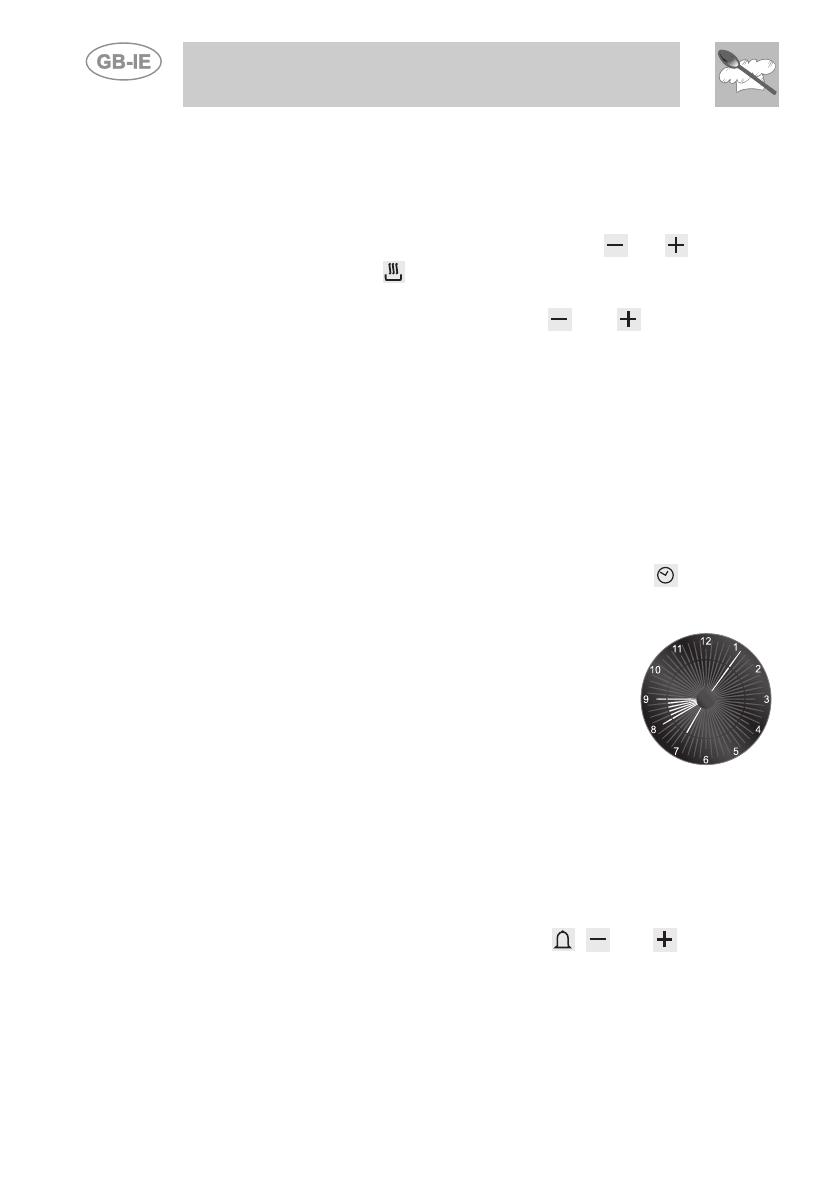
- The image on the right shows an example of
programming: the current time is 7.06 and
cooking is programmed to start at 8 o'clock
and finish at 9.
- At 8 o'clock, the inside segments between 8
and 9 will start to flash and the hour pointer will
remain still.
Caution: for the oven to start cooking after the programming
procedure just described, the thermostat and function selector must
be properly set on the temperature and function required.
5.3.4 "DEMO" Function
Models with analogue/digital programmer feature a "DEMO" function
which deactivates the heating elements while leaving the other functions
unchanged. To activate it, simply press the
, and keys for 3/4
seconds. A confirmation beep will inform the user that the function is
active. To deactivate it, simply repeat the same procedure.
Instructions for the user
6. USE OF THE COOKING HOB
6.1 Lighting of the cooking hob burners
Before lighting the hob burners check that the flame caps are in the
correct position and that their burner caps are in place, making sure that
the holes A in the flame caps correspond to the spark plugs and
thermocouples.
Grid B should be used with Chinese woks.
Each knob corresponds to the burner
indicated. The appliance is equipped with
an electric lighting device. To light the
burners, press and turn the knob
anticlockwise to the large flame symbol
/ .
Keep the knob pressed for about 2 seconds to let the thermocouple
heat up.
If the burner turns off when the knob is released, it means that the
thermocouple isn’t hot enough. Repeat ignition and keep the knob
pressed longer.
Once the burner has been ignited, the flame can be regulated as
required.
Always check that the control knobs are in the position (off) when
you finish using the hob.
If the burners turn off accidentally, a safety device will trip after about 20
seconds to cut off gas flow (even with the gas tap open).
51
Instructions for the user
52
6.2 Practical advice for using the cooking hob burners
For better use of the burners and lower gas consumption, use covered
containers that are proportional in size to the burner to prevent the flame
from licking the sides (see paragraph “6.3 Diameter of containers").
When water reaches the boiling point, lower the flame so that it doesn’t
overflow. To avoid burns or damage to the hob, all recipients or griddle
plates must be placed within the perimeter of the cooking hob. All
containers have to have a flat and smooth bottom. When using fats or
oils, be extremely careful that they don’t overheat and catch fire.
If the flame accidentally goes out, turn off the control knob and wait at
least 1 minute before trying to re-light the burner.
6.3 Diameter of containers
BURNERS
1 Auxiliary
2 Semi rapid
3 Rapid
4 Ultra rapid
5 Fish pan
Ø min. and max.
(in cm)
12-14
16-20
18-26
20-26
use special
oval-shaped pan
7. USE OF THE OVEN
Before using the oven make sure that the the analog programmer shows
the symbol (see paragraph "5.2.4 Manual mode cooking ").
In models equipped with analogue digital timer, the user has only to
press the central key for 1/2 seconds to enable use of the oven on first
use or after a power blackout.
7.1 Warnings and general advice
Before using the oven for the first time, pre-heat it to maximum
temperature (250°C) long enough to burn any manufacturing oily
residues which could give the food a bad taste.
Instructions for the user
To prevent any steam in the oven creating
problems, open the door in two stages: half open
(5 cm approx.) for 4-5 seconds and then fully
open. To access food, always leave the door
open as short a time as possible to prevent the
temperature in the oven from falling and ruining
the food.
5 cm
During cooking, do not cover the bottom of the oven with aluminium or
tin foil, and do not place pans or trays on it; this may damage the enamel
coating. If you wish to use greaseproof paper, position it so that it does
not interfere with the hot air circulation inside the oven.
7.2 Oven Light
It comes on when the function switch knob is turned to any position.
7.3 Cooling fan system
The appliance is equipped with a cooling system, which comes into
operation as soon as a cooking function is selected. This is also the case
for cooking with the minute minder.
Fans cause a steady outflow of air from the rear top skirt board on the
rear of the cooking hob, which may continue for a brief period of time
even after the oven has been turned off.
This ventilation system ensures that the temperatures on the outside of
the appliance meet the standards required by the current regulations.
7.4 Storage drawer
The storage drawer is at the bottom of the
cooker, underneath the oven. For access,
pull the bottom of the door.
Never store inflammable materials such as
rags, paper or the like. The compartment is
intended only for holding the metal
accessories of the range.
Never open the storage compartment when the oven is on and still hot.
The temperature inside may be very high.
53
Instructions for the user
54
8. AVAILABLE ACCESSORIES
The oven features 4 support positions for
plates and racks of different height.
Oven grill: for cooking food on plates, small
cakes, roasts or food requiring light grilling.
Plate grill: for placing above plate for
cooking foods that might drip.
Oven plate: useful for catching fat from
foods on the grill above.
Pastry plate: for baking cakes, pizza and
oven desserts.
Roasting spit: useful for cooking chicken,
sausages and anything else requiring
uniform cooking over the whole surface.
Spit supports: to be inserted in the holes of
the oven plate before mounting the roasting
spit.
Accessories on Request
You can order the lower base through Authorised Assistance Centres.
  • Page 1 1
  • Page 2 2
  • Page 3 3
  • Page 4 4
  • Page 5 5
  • Page 6 6
  • Page 7 7
  • Page 8 8
  • Page 9 9
  • Page 10 10
  • Page 11 11
  • Page 12 12
  • Page 13 13
  • Page 14 14
  • Page 15 15
  • Page 16 16
  • Page 17 17
  • Page 18 18
  • Page 19 19
  • Page 20 20
  • Page 21 21
  • Page 22 22
  • Page 23 23
  • Page 24 24
  • Page 25 25
  • Page 26 26
  • Page 27 27
  • Page 28 28
  • Page 29 29
  • Page 30 30
  • Page 31 31

Smeg A1-6 User manual

Category
Cookers
Type
User manual
This manual is also suitable for

Ask a question and I''ll find the answer in the document

Finding information in a document is now easier with AI