SMC SMC8126PL2-F User manual
- Category
- Network switches
- Type
- User manual
This manual is also suitable for

INSTALLATION GUIDE
ta
TigerSwitch
TM
10/100/1000
L2-Lite SMB PoE Gigabit Switch
SMC8126PL2-F

20 Mason
Irvine, CA 92618
Phone: (949) 679-8000
TigerSwitch 10/100/1000
Installation Guide
From SMC's Tiger line of feature-rich workgroup LAN solutions
September 2009
Pub. # 150200000032A
E092009-MW-R01

Information furnished by SMC Networks, Inc. (SMC) is believed to be accurate and
reliable. However, no responsibility is assumed by SMC for its use, nor for any
infringements of patents or other rights of third parties which may result from its use. No
license is granted by implication or otherwise under any patent or patent rights of SMC.
SMC reserves the right to change specifications at any time without notice.
Copyright © 2009 by
SMC Networks, Inc.
20 Mason
Irvine, CA 92618
All rights reserved. Printed in China
Trademarks:
SMC is a registered trademark; and EZ Switch, TigerStack and TigerSwitch are
trademarks of SMC Networks, Inc. Other product and company names are trademarks or
registered trademarks of their respective holders.

Warranty and Product Registration
To register SMC products and to review the detailed warranty statement, please refer to
the Support Section of the SMC Website at http://www.smc.com.

i
Compliances and Safety Warnings
FCC - Class A
This equipment has been tested and found to comply with the limits for a Class A digital
device, pursuant to part 15 of the FCC Rules. These limits are designed to provide
reasonable protection against harmful interference when the equipment is operated in a
commercial environment. This equipment generates, uses, and can radiate radio
frequency energy and, if not installed and used in accordance with the instruction manual,
may cause harmful interference to radio communications. Operation of this equipment in
a residential area is likely to cause harmful interference in which case the user will be
required to correct the interference at his own expense.
You are cautioned that changes or modifications not expressly approved by the party
responsible for compliance could void your authority to operate the equipment.
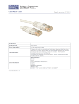
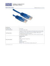
You may use unshielded twisted-pair (UTP) for RJ-45 connections - Category 3 or better
for 10 Mbps connections, Category 5 or better for 100 Mbps connections, Category 5, 5e,
or 6 for 1000 Mbps connections. For fiber optic connections, you may use 50/125 or 62.5/
125 micron multimode fiber or 9/125 micron single-mode fiber.
Industry Canada - Class A
This digital apparatus does not exceed the Class A limits for radio noise emissions from
digital apparatus as set out in the interference-causing equipment standard entitled
“Digital Apparatus,” ICES-003 of the Department of Communications.
Cet appareil numérique respecte les limites de bruits radioélectriques applicables aux
appareils numériques de Classe A prescrites dans la norme sur le matériel brouilleur:
“Appareils Numériques,” NMB-003 édictée par le ministère des Communications.

ii
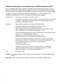
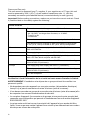
CE Mark Declaration of Conformance for EMI and Safety (EEC)
This information technology equipment complies with the requirements of the Council
Directive 89/336/EEC on the Approximation of the laws of the Member States relating to
Electromagnetic Compatibility and 73/23/EEC for electrical equipment used within certain
voltage limits and the Amendment Directive 93/68/EEC. For the evaluation of the
compliance with these Directives, the following standards were applied:
Caution: Do not plug a phone jack connector in the RJ-45 port. This may damage this
device.
Attention: Les raccordeurs ne sont pas utilisés pour le système téléphonique!
RFI Emission: • Limit class A according to EN 55022:1998
• Limit class A for harmonic current emission according to EN 61000-3-2/1995
• Limitation of voltage fluctuation and flicker in low-voltage supply system
according to EN 61000-3-3/1995
Immunity: • Product family standard according to EN 55024:1998
• Electrostatic Discharge according to EN 61000-4-2:1995
(Contact Discharge: ±4 kV, Air Discharge: ±8 kV)
• Radio-frequency electromagnetic field according to EN 61000-4-3:1996
(80 - 1000 MHz with 1 kHz AM 80% Modulation: 3 V/m)
• Electrical fast transient/burst according to EN 61000-4-4:1995 (AC/DC power
supply: ±1 kV, Data/Signal lines: ±0.5 kV)
• Surge immunity test according to EN 61000-4-5:1995
(AC/DC Line to Line: ±1 kV, AC/DC Line to Earth: ±2 kV)
• Immunity to conducted disturbances, Induced by radio-frequency fields:
EN 61000-4-6:1996 (0.15 - 80 MHz with 1 kHz AM 80% Modulation: 3 V/m)
• Power frequency magnetic field immunity test according to
EN 61000-4-8:1993
(1 A/m at frequency 50 Hz)
• Voltage dips, short interruptions and voltage variations immunity test
according to EN 61000-4-11:1994 (>95% Reduction @10 ms, 30%
Reduction @500 ms, >95% Reduction @5000 ms)
LVD: • EN 60950-1:2001

iii
Safety Compliance
Warning: Fiber Optic Port Safety
Avertissment: Ports pour fibres optiques - sécurité sur le plan optique
Warnhinweis: Faseroptikanschlüsse - Optische Sicherheit
Advertencia: Seguridad del puerto de fibra óptica
PSE Alarm
本製品に同梱いたしております電源コードセットは、本製品専用です。本電源コード
セットは、本製品以外の製品並びに他の用途でご使用いただくことは出来ません。
製品本体に同梱された電源コードセットを利用し、他製品の電源コードセットを使用し
ないで下さい。
Power Cord Safety
Please read the following safety information carefully before installing the switch:
WARNING: Installation and removal of the unit must be carried out by qualified personnel
only.
• The unit must be connected to an earthed (grounded) outlet to comply with
international safety standards.
• Do not connect the unit to an A.C. outlet (power supply) without an earth (ground)
connection.
• The appliance coupler (the connector to the unit and not the wall plug) must have
a configuration for mating with an EN 60320/IEC 320 appliance inlet.
• The socket outlet must be near to the unit and easily accessible. You can only
remove power from the unit by disconnecting the power cord from the outlet.
• This unit operates under SELV (Safety Extra Low Voltage) conditions according to
IEC 60950. The conditions are only maintained if the equipment to which it is
connected also operates under SELV conditions.
When using a fiber optic port, never look at the transmit laser while it is
powered on. Also, never look directly at the fiber TX port and fiber cable
ends when they are powered on.
Ne regardez jamais le laser tant qu'il est sous tension. Ne regardez
jamais directement le port TX (Transmission) à fibres optiques et les
embouts de câbles à fibres optiques tant qu'ils sont sous tension.
Niemals ein Übertragungslaser betrachten, während dieses
eingeschaltet ist. Niemals direkt auf den Faser-TX-Anschluß und auf
die Faserkabelenden schauen, während diese eingeschaltet sind.
Cuando utilice un puerto de fibra óptica, nunca mire hacia el láser
de transmisión mientras el mismo esté energizado. Asimismo,
nunca mire directamente hacia el puerto de fibra óptica de
transmisión ni a los extremos del cable de fibra óptica cuando
estén energizados.
CLASS I
LASER DEVICE
DISPOSITIF LASER
DE CLASSE I
LASERGER
DER KLASSE I
ÄT
LASERGER
DER KLASSE I
ÄT

iv
France and Peru only
This unit cannot be powered from IT
†
supplies. If your supplies are of IT type, this unit
must be powered by 230 V (2P+T) via an isolation transformer ratio 1:1, with the
secondary connection point labelled Neutral, connected directly to earth (ground).
Important! Before making connections, make sure you have the correct cord set. Check
it (read the label on the cable) against the following:
Veuillez lire à fond l'information de la sécurité suivante avant d'installer le Switch:
AVERTISSEMENT: L’installation et la dépose de ce groupe doivent être confiés à un
personnel qualifié.
• Ne branchez pas votre appareil sur une prise secteur (alimentation électrique)
lorsqu'il n'y a pas de connexion de mise à la terre (mise à la masse).
• Vous devez raccorder ce groupe à une sortie mise à la terre (mise à la masse) afin
de respecter les normes internationales de sécurité.
• Le coupleur d’appareil (le connecteur du groupe et non pas la prise murale) doit
respecter une configuration qui permet un branchement sur une entrée d’appareil
EN 60320/IEC 320.
• La prise secteur doit se trouver à proximité de l’appareil et son accès doit être
facile. Vous ne pouvez mettre l’appareil hors circuit qu’en débranchant son cordon
électrique au niveau de cette prise.
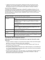
Power Cord Set
U.S.A. and Canada The cord set must be UL-approved and CSA certified.
The minimum specifications for the flexible cord are:
- No. 18 AWG - not longer than 2 meters, or 16 AWG.
- Type SV or SJ
- 3-conductor
The cord set must have a rated current capacity of at least 10 A
The attachment plug must be an earth-grounding type with NEMA
5-15P (15 A, 125 V) or NEMA 6-15P (15 A, 250 V) configuration.
Denmark The supply plug must comply with Section 107-2-D1, Standard
DK2-1a or DK2-5a.
Switzerland The supply plug must comply with SEV/ASE 1011.
U.K. The supply plug must comply with BS1363 (3-pin 13 A) and be fitted
with a 5 A fuse which complies with BS1362.
The mains cord must be <HAR> or <BASEC> marked and be of type
HO3VVF3GO.75 (minimum).
Europe The supply plug must comply with CEE7/7 (“SCHUKO”).
The mains cord must be <HAR> or <BASEC> marked and be of type
HO3VVF3GO.75 (minimum).
IEC-320 receptacle.

v
• L’appareil fonctionne à une tension extrêmement basse de sécurité qui est
conforme à la norme IEC 60950. Ces conditions ne sont maintenues que si
l’équipement auquel il est raccordé fonctionne dans les mêmes conditions.
France et Pérou uniquement:
Ce groupe ne peut pas être alimenté par un dispositif à impédance à la terre. Si vos
alimentations sont du type impédance à la terre, ce groupe doit être alimenté par une
tension de 230 V (2 P+T) par le biais d’un transformateur d’isolement à rapport 1:1, avec
un point secondaire de connexion portant l’appellation Neutre et avec raccordement
direct à la terre (masse).
Seguridad del cable de alimentación eléctrica
Antes de instalar el conmutador lea atentamente la siguiente información sobre
seguridad:
• Se debe conectar el equipo a un tomacorriente puesto a tierra (tierra física) para
satisfacer las normas internacionales sobre seguridad.
• No conecte el equipo a un tomacorriente (suministro eléctrico) de CA sin una
conexión de tierra (tierra física).
• El acoplador del dispositivo (el conector que va hacia el equipo y no el enchufe que
va a la pared) deberá tener una configuración que coincida con la de la entrada de
un dispositivo EN 60320/IEC 320.
• El tomacorriente debe estar cerca del equipo y ser fácilmente accesible. Sólo se
puede quitar la alimentación eléctrica al equipo desenchufando el cable de
alimentación eléctrica del tomacorriente.
Cordon électrique - Il doit être agréé dans le pays d’utilisation
Etats-Unis et
Canada:
Le cordon doit avoir reçu l’homologation des UL et un certificat de la
CSA.
Les spécifications minimales pour un cable flexible sont AWG No. 18,
ouAWG No. 16 pour un cable de longueur inférieure à 2 mètres.
- type SV ou SJ
- 3 conducteurs
Le cordon doit être en mesure d’acheminer un courant nominal d’au
moins 10 A.
La prise femelle de branchement doit être du type à mise à la terre
(mise à la masse) et respecter la configuration NEMA 5-15P (15 A,
125 V) ou NEMA 6-15P (15 A, 250 V).
Danemark: La prise mâle d’alimentation doit respecter la section 107-2 D1 de la
norme DK2 1a ou DK2 5a.
Suisse: La prise mâle d’alimentation doit respecter la norme SEV/ASE 1011.
Europe La prise secteur doit être conforme aux normes CEE 7/7 (“SCHUKO”)
LE cordon secteur doit porter la mention <HAR> ou <BASEC> et doit
être de type HO3VVF3GO.75 (minimum).

vi
• Este equipo opera bajo las condiciones SELV (Safety Extra Low Voltage o Voltaje
extra bajo de seguridad) de acuerdo con la norma IEC 60950. Las condiciones
sólo se mantienen si la equipo al cual está conectado también opera bajo
condiciones SELV.
Francia y Perú únicamente
Este equipo no puede ser energizado desde suministros IT†. Si su servicio eléctrico es
del tipo IT, este equipo deberá ser alimentado con 230 V (2P+T) a través de un
transformador de aislamiento de relación 1:1, con el punto de conexión del secundario
rotulado Neutro conectado directamente a tierra (tierra física).
¡Importante! Antes de efectuar conexiones, asegúrese de que disponga del conjunto
correcto de cables. Verifíquelo (lea la etiqueta del cable) contra lo siguiente:
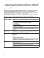
Conjunto de cables de alimentación eléctrica
EE.UU. y Canadá El conjunto de cables deberá estar aprobado por UL y certificado por
CSA.
Las especificaciones mínimas del cable flexible son:
- Nº 18 AWG, no mayor de 2 metros, o 16 AWG.
- Tipo SV o SJ
- tres conductores
El conjunto de cables deberá tener una capacidad de corriente
nominal de al menos 10 A.
El enchufe de conexión deberá ser del tipo con puesta a tierra y tener
una configuración NEMA 5-15P (15 A, 125 V) o NEMA 6-15P (15 A,
250 V).
Dinamarca El enchufe de alimentación eléctrica deberá satisfacer la Sección
107-2-D1 de las normas DK2-1a o DK2-5a.
Suiza El enchufe de alimentación eléctrica deberá satisfacer la norma SEV/
ASE 1011.
Reino Unido El enchufe de alimentación eléctrica deberá satisfacer la norma
BS1363 (tres clavijas 13 A) y estar provisto de un fusible de 5 A que
satisfaga la norma BS1362.
El cable de alimentación eléctrica debe estar marcado como <HAR>
o <BASEC> y ser del tipo HO3VVF3GO.75 (mínimo).
Europa El enchufe de alimentación eléctrica deberá satisfacer la norma
CEE7/7 (“SCHUKO”).
El cable de alimentación eléctrica debe estar marcado como <HAR>
o <BASEC> y ser del tipo HO3VVF3GO.75 (mínimo).
Receptáculo IEC-320.

vii
Bitte unbedingt vor dem Einbauen des Switches die folgenden
Sicherheitsanweisungen durchlesen:
WARNUNG: Die Installation und der Ausbau des Geräts darf nur durch Fachpersonal
erfolgen.
• Das Gerät sollte nicht an eine ungeerdete Wechselstromsteckdose angeschlossen
werden.
• Das Gerät muß an eine geerdete Steckdose angeschlossen werden, welche die
internationalen Sicherheitsnormen erfüllt.
• Der Gerätestecker (der Anschluß an das Gerät, nicht der Wandsteckdosenstecker)
muß einen gemäß EN 60320/IEC 320 konfigurierten Geräteeingang haben.
• Die Netzsteckdose muß in der Nähe des Geräts und leicht zugänglich sein. Die
Stromversorgung des Geräts kann nur durch Herausziehen des Gerätenetzkabels
aus der Netzsteckdose unterbrochen werden.
• Der Betrieb dieses Geräts erfolgt unter den SELV-Bedingungen
(Sicherheitskleinstspannung) gemäß IEC 60950. Diese Bedingungen sind nur
gegeben, wenn auch die an das Gerät angeschlossenen Geräte unter
SELV-Bedingungen betrieben werden.
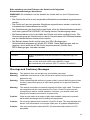
Warnings and Cautionary Messages
Stromkabel. Dies muss von dem Land, in dem es benutzt wird geprüft werden:
Schweiz Dieser Stromstecker muß die SEV/ASE 1011Bestimmungen ein-
halten.
Europe Das Netzkabel muß vom Typ HO3VVF3GO.75 (Mindestanforderung)
sein und die Aufschrift <HAR> oder <BASEC> tragen.
Der Netzstecker muß die Norm CEE 7/7 erfüllen (”SCHUKO”).
Warning: This product does not contain any serviceable user parts.
Warning: Installation and removal of the unit must be carried out by qualified
personnel only.
Warning: When connecting this device to a power outlet, connect the field ground lead
on the tri-pole power plug to a valid earth ground line to prevent electrical
hazards.
Warning: This switch uses lasers to transmit signals over fiber optic cable. The lasers
are compliant with the requirements of a Class 1 Laser Product and are
inherently eye safe in normal operation. However, you should never look
directly at a transmit port when it is powered on.
Caution: Wear an anti-static wrist strap or take other suitable measures to prevent
electrostatic discharge when handling this equipment.
Caution: Do not plug a phone jack connector in the RJ-45 port. This may damage this
device. Les raccordeurs ne sont pas utilisé pour le système téléphonique!
Caution: Use only twisted-pair cables with RJ-45 connectors that conform to FCC
standards.

viii
Advertencias y mensajes de precaución
Environmental Statement
The manufacturer of this product endeavours to sustain an environmentally-friendly policy
throughout the entire production process. This is achieved though the following means:
• Adherence to national legislation and regulations on environmental production
standards.
• Conservation of operational resources.
• Waste reduction and safe disposal of all harmful un-recyclable by-products.
• Recycling of all reusable waste content.
• Design of products to maximize recyclables at the end of the product’s life span.
• Continual monitoring of safety standards.
End of Product Life Span
This product is manufactured in such a way as to allow for the recovery and disposal of all
included electrical components once the product has reached the end of its life.
Manufacturing Materials
There are no hazardous nor ozone-depleting materials in this product.
Documentation
All printed documentation for this product uses biodegradable paper that originates from
sustained and managed forests. The inks used in the printing process are non-toxic.
Advertencia: Este producto no contiene ninguna pieza reparable por el usuario.
Advertencia: La instalación y remoción del equipo sólo debe ser llevada a cabo por
personal calificado.
Advertencia: Cuando enchufe este aparato a un tomacorriente, conecte el cable de tierra
del enchufe tripolar a una línea válida de tierra física para prevenir riesgos
de tipo eléctrico.
Advertencia: Este conmutador utiliza láseres para transmitir señales a través de un cable
de fibra óptica. Los láseres satisfacen los requisitos de un producto láser
Clase 1 y son intrínsecamente seguros para los ojos en operación normal.
Sin embargo, nunca deberá mirar directamente a un puerto de transmisión
cuando esté energizado..
Precaución Cuando manipule este equipo utilice una correa para la muñeca que
proteja contra la electricidad estática o adopte otras medidas adecuadas
tendientes a impedir las descargas electrostáticas.
Precaución No inserte en el puerto RJ-45 un conector telefónico. Esto podría dañar el
dispositivo. Les raccordeurs ne sont pas utilisé pour le système
téléphonique!
Precaución Sólo utilice cables de par retorcido con conectores RJ-45 que satisfagan
las normas FCC.

ix
Purpose
This guide details the hardware features of the switches, including their physical and
performance-related characteristics, and how to install each switch.
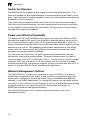
Audience
This guide is for system administrators with a working knowledge of network
management. You should be familiar with switching and networking concepts.
Esta guía es para los administradores de sistemas que cuenten con conocimientos
básicos de gestión de redes. Usted deberá estar familiarizado con los conceptos de
conmutación y operación en red.
Related Publications
The following publication gives specific information on how to operate and use the
management functions of the switches:
The Management Guide
Also, as part of both switches’ firmware, there is an online web-based help that describes
all management related features.

x

xi
Contents
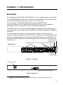
Chapter 1: Introduction 1-1
Overview 1-1
Switch Architecture 1-2
Power-over-Ethernet Capability 1-2
Network Management Options 1-2
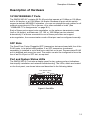
Description of Hardware 1-3
10/100/1000BASE-T Ports 1-3
SFP Slots 1-3
Port and System Status LEDs 1-3
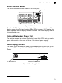
Mode PoE/Link Button 1-5
Optional Redundant Power Unit 1-5
Power Supply Socket 1-5
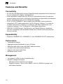
Features and Benefits 1-5
Connectivity 1-5
Expandability 1-6
Performance 1-6
Management 1-6
Chapter 2: Network Planning 2-1
Introduction to Switching 2-1
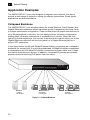
Application Examples 2-2
Collapsed Backbone 2-2
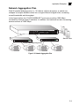
Network Aggregation Plan 2-3
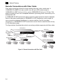
Remote Connections with Fiber Cable 2-4
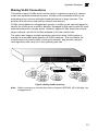
Making VLAN Connections 2-5
Application Notes 2-6
Chapter 3: Installing the Switch 3-1
Selecting a Site 3-1
Ethernet Cabling 3-1
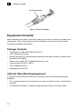
Equipment Checklist 3-2
Package Contents 3-2
Optional Rack-Mounting Equipment 3-2
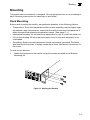
Mounting 3-3
Rack Mounting 3-3
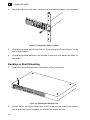
Desktop or Shelf Mounting 3-4
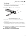
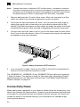
Installing an Optional SFP Transceiver 3-5
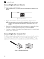
Connecting to a Power Source 3-6

xii
Contents
Connecting to the Console Port 3-6
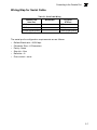
Wiring Map for Serial Cable 3-7
Chapter 4: Making Network Connections 4-1
Connecting Network Devices 4-1
Twisted-Pair Devices 4-1
Cabling Guidelines 4-1
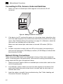
Connecting to PCs, Servers, Hubs and Switches 4-2
Network Wiring Connections 4-2
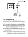
Fiber Optic SFP Devices 4-3
Connectivity Rules 4-4
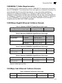
1000BASE-T Cable Requirements 4-5
1000 Mbps Gigabit Ethernet Collision Domain 4-5
100 Mbps Fast Ethernet Collision Domain 4-5
10 Mbps Ethernet Collision Domain 4-6
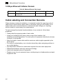
Cable Labeling and Connection Records 4-6
Appendix A: Troubleshooting A-1
Diagnosing Switch Indicators A-1
Power and Cooling Problems A-1
Installation A-1
In-Band Access A-2
Appendix B: Cables B-1
Twisted-Pair Cable and Pin Assignments B-1
10BASE-T/100BASE-TX Pin Assignments B-1
Straight-Through Wiring B-2
Crossover Wiring B-2
1000BASE-T Pin Assignments B-3
Cable Testing for Existing Category 5 Cable B-4
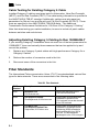
Adjusting Existing Category 5 Cabling to Run 1000BASE-T B-4
Fiber Standards B-4
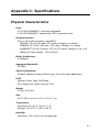
Appendix C: Specifications C-1
Physical Characteristics C-1
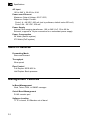
Switch Features C-2
Management Features C-2
Standards C-3
Compliances C-3


xiv
Tables
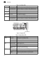
Table 1-1 Port Status LEDs 1-4
Table 1-2 System Status LEDs 1-4
Table 3-1 Serial Cable Wiring 3-7
Table 4-1 Maximum 1000BASE-T Gigabit Ethernet Cable Length 4-5
Table 4-2 Maximum 1000BASE-SX Gigabit Ethernet Cable Length 4-5
Table 4-3 Maximum 1000BASE-LX Gigabit Ethernet Cable Length 4-5
Table 4-4 Maximum 1000BASE-ZX Gigabit Ethernet Cable Length 4-5
Table 4-5 Maximum Fast Ethernet Cable Length 4-5
Table 4-6 Maximum Ethernet Cable Length 4-6
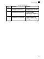
Table A-1 Troubleshooting Chart A-1
Table B-1 10/100BASE-TX MDI and MDI-X Port Pinouts B-2
Table B-2 1000BASE-T MDI and MDI-X Port Pinouts B-3
Table B-3 Fiber Standards B-4
Table D-1 TIgerSwitch 10/100/1000 Products and Accessories D-1

xv
Figures
Figure 1-1 Front Panel 1-1
Figure 1-2 Rear Panel 1-1
Figure 1-3 Port LEDs 1-3
Figure 1-4 System LEDs 1-4
Figure 1-5 Mode Selection 1-5
Figure 1-6 Power Supply Socket 1-5
Figure 2-1 Collapsed Backbone 2-2
Figure 2-2 Network Aggregation Plan 2-3
Figure 2-3 Remote Connections with Fiber Cable 2-4
Figure 2-4 Making VLAN Connections 2-5
Figure 3-1 RJ-45 Connections 3-2
Figure 3-2 Attaching the Brackets 3-3
Figure 3-3 Installing the Switch in a Rack 3-4
Figure 3-4 Attaching the Adhesive Feet 3-4
Figure 3-5 Inserting an SFP Transceiver into a Slot 3-5
Figure 3-6 Power Socket 3-6
Figure 3-7 Serial Port (RJ-45) Pin-Out 3-6
Figure 4-1 Making Twisted-Pair Connections 4-2
Figure 4-2 Network Wiring Connections 4-3
Figure 4-3 Making Connections to SFP Transceivers 4-4
Figure B-1 RJ-45 Connector Pin Numbers B-1
Figure B-2 Straight-through Wiring B-2
Figure B-3 Crossover Wiring B-3
Figure E-1 Fijación de los soportes E-2
Figure E-2 Instalación del conmutador en un bastidor E-2

xvi
Page is loading ...
Page is loading ...
Page is loading ...
Page is loading ...
Page is loading ...
Page is loading ...
Page is loading ...
Page is loading ...
Page is loading ...
Page is loading ...
Page is loading ...
Page is loading ...
Page is loading ...
Page is loading ...
Page is loading ...
Page is loading ...
Page is loading ...
Page is loading ...
Page is loading ...
Page is loading ...
Page is loading ...
Page is loading ...
Page is loading ...
Page is loading ...
Page is loading ...
Page is loading ...
Page is loading ...
Page is loading ...
Page is loading ...
Page is loading ...
Page is loading ...
Page is loading ...
Page is loading ...
Page is loading ...
Page is loading ...
Page is loading ...
Page is loading ...
Page is loading ...
Page is loading ...
Page is loading ...
Page is loading ...
Page is loading ...
Page is loading ...
Page is loading ...
Page is loading ...
Page is loading ...
Page is loading ...
Page is loading ...
-
 1
1
-
 2
2
-
 3
3
-
 4
4
-
 5
5
-
 6
6
-
 7
7
-
 8
8
-
 9
9
-
 10
10
-
 11
11
-
 12
12
-
 13
13
-
 14
14
-
 15
15
-
 16
16
-
 17
17
-
 18
18
-
 19
19
-
 20
20
-
 21
21
-
 22
22
-
 23
23
-
 24
24
-
 25
25
-
 26
26
-
 27
27
-
 28
28
-
 29
29
-
 30
30
-
 31
31
-
 32
32
-
 33
33
-
 34
34
-
 35
35
-
 36
36
-
 37
37
-
 38
38
-
 39
39
-
 40
40
-
 41
41
-
 42
42
-
 43
43
-
 44
44
-
 45
45
-
 46
46
-
 47
47
-
 48
48
-
 49
49
-
 50
50
-
 51
51
-
 52
52
-
 53
53
-
 54
54
-
 55
55
-
 56
56
-
 57
57
-
 58
58
-
 59
59
-
 60
60
-
 61
61
-
 62
62
-
 63
63
-
 64
64
-
 65
65
-
 66
66
-
 67
67
-
 68
68


SMC SMC8126PL2-F User manual
- Category
- Network switches
- Type
- User manual
- This manual is also suitable for
Ask a question and I''ll find the answer in the document
Finding information in a document is now easier with AI
Related papers
Other documents
-
Accton Technology ES4524MV-PoE-FLF-38 User manual
-
Sweex SW118 Datasheet
-
SMC Networks 10g User manual
-
-
 Cables Direct URT-600W Datasheet
-
 Cables Direct URT-600B Datasheet
-
-
Cables Direct URT-600R Datasheet
-
Edge-Core ES3528M V1 Installation guide
-

