
Contents
Page
IMPORTANT!
Please Read Before Starting.................................. 1
1. GENERAL.......................................................... 2
1-1. Tools Required for Installation (not supplied)
1-2. Accessories Supplied with Indoor Unit
1-3. Optional Copper Tubing Kit
1-4. Type of Copper Tube and Insulation Material
1-5. Field Wiring
1-6. Additional Materials Required for Installation
2. INSTALLATION SITE SELECTION................... 3
2-1. Indoor Unit
2-2. Outdoor Unit
3. HOW TO INSTALL THE INDOOR UNIT ........... 5
3-1. Remove the Rear Panel from the Unit
3-2. Make a Hole
3-3. Install the Rear Panel on the Wall
3-4. Remove the Grille to Install the Indoor Unit
3-5. Shape the Indoor Side Tubing
3-6. Wiring Instructions
3-7. Recommended Wire Length and Diameter
3-8. Wiring Instructions for Inter-unit Connections
3-9. Mounting
3-10. Drain Hose
Model Combinations
Combine indoor and outdoor units only as listed
below.
Indoor Unit Outdoor Units
KS2432A C2432
CL2432
Power supply: 60Hz, single-phase, 208/230V
INSTALLATION INSTRUCTIONS
– Split System Air Conditioner – COOL/DRY Model
Use this manual when installing combined
models of indoor unit KS2432A and outdoor
unit C2432 or CL2432 only.
On items not included in this manual, see the
Installation Instructions (No. 85464179694003)
packed in the outdoor unit model C2432 or
CL2432.
Units should be installed by a licensed contractor
according to local code requirements.
ATTENTION
4. REFRIGERANT TUBING.................................. 13
4-1. Indoor Unit Tubing
4-2. Outdoor Unit Tubing
4-3. Connecting Tubing between Indoor and
Outdoor Units
4-4. Insulation of Refrigerant Tubing
4-5. Taping the Tubes
4-6. Finishing the Installation
5. REMOTE CONTROL UNIT INSTALLATION
POSITION ......................................................... 16
5-1. Mounting on a Wall
In Canada
SANYO FISHER COMPANY SANYO Canada Inc.
A DIVISION OF SANYO NORTH AMERICA CORPORATION 300 Applewood Crescent
21605 Plummer Street Concord, Ontario
85264189704003 © SANYO 2003 Chatsworth, CA 91311 U.S.A. L4K 5C7, Canada
W
01-386 AirCon 12/11/01 4:48 PM Page a

1
IMPORTANT!
Please Read Before Starting
This air conditioning system meets strict safety and operat-
ing standards. As the installer or service person, it is an
important part of your job to install or service the system so
it operates safely and efficiently.
For safe installation and trouble-free operation, you must:
●
Carefully read this instruction booklet before beginning.
●
Follow each installation or repair step exactly as
shown.
●
Observe all local, state, and national electrical codes.
●
Pay close attention to all warning and caution notices
given in this manual.
This symbol refers to a hazard or
unsafe practice which can result
in severe personal injury or
death.
This symbol refers to a hazard
or unsafe practice which can
result in personal injury or prod-
uct or property damage.
If Necessary, Get Help
These instructions are all you need for most installation
sites and maintenance conditions. If you require help for a
special problem, contact our sales/service outlet or your
certified dealer for additional instructions.
In Case of Improper Installation
The manufacturer shall in no way be responsible for
improper installation or maintenance service, including
failure to follow the instructions in this document.
SPECIAL PRECAUTIONS
When Wiring
ELECTRICAL SHOCK CAN CAUSE SEVERE PER-
SONAL INJURY OR DEATH. ONLY A QUALIFIED,
EXPERIENCED ELECTRICIAN SHOULD ATTEMPT
TO WIRE THIS SYSTEM.
• Do not supply power to the unit until all
wiring and tubing are completed or reconnected and
checked.
• Highly dangerous electrical voltages are used in this
system. Carefully refer to the wiring diagram and these
instructions when wiring. Improper connections and
inadequate grounding can cause accidental injury or
death.
• Ground the unit following local electrical codes.
• Connect all wiring tightly. Loose wiring may cause over-
heating at connection points and a possible fire hazard.
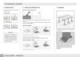
When Transporting
Be careful when picking up and moving the indoor and out-
door units. Get a partner to help, and bend your knees when
lifting to reduce strain on your back. Sharp edges or thin alu-
minum fins on the air conditioner can cut your fingers.
When Installing…
…In a Ceiling, Wall or Floor
Make sure the ceiling/wall/floor is strong enough to hold
the unit’s weight. It may be necessary to construct a
strong wood or metal frame to provide added support.
…In a Room
Properly insulate any tubing run inside a room to prevent
“sweating” that can cause dripping and water damage to
walls and floors.
…In Moist or Uneven Locations
Use a raised concrete pad or concrete blocks to provide a
solid, level foundation for the outdoor unit. This prevents
water damage and abnormal vibration.
…In an Area with High Winds
Securely anchor the outdoor unit down with bolts and a
metal frame. Provide a suitable air baffle.
…In a Snowy Area (for Heat Pump-type Systems)
Install the outdoor unit on a raised platform that is higher
than drifting snow. Provide snow vents.
When Connecting Refrigerant Tubing
• Use the flare method for connecting tubing.
• Apply refrigerant lubricant to the matching surfaces of
the flare and union tubes before connecting them, then
tighten the nut with a torque wrench for a leak-free con-
nection.
• Check carefully for leaks before starting the test run.
When Servicing
• Turn the power OFF at the main power box (mains)
before opening the unit to check or repair electrical
parts and wiring.
• Keep your fingers and clothing away from any moving
parts.
• Clean up the site after you finish, remembering to check
that no metal scraps or bits of wiring have been left
inside the unit being serviced.
Others
• Ventilate any enclosed areas when installing or testing
the refrigeration system. Escaped refrigerant gas, on
contact with fire or heat, can produce dangerously toxic
gas.
• Confirm upon completing installation that no refrigerant
gas is leaking. If escaped gas comes in contact with a
stove, gas water heater, electric room heater or other
heat source, it can produce dangerously toxic gas.
WARNING
WARNING
CAUTION
CAUTION
01-386 AirCon 12/11/01 4:48 PM Page 1

2
1. General
This booklet briefly outlines where and how to install the
air conditioning system. Please read over the entire set
of instructions for the indoor and outdoor units and make
sure all accessory parts listed are with the system before
beginning.
1-1. Tools Required for Installation (not supplied)
1. Standard screwdriver
2. Phillips head screwdriver
3. Knife or wire stripper
4. Tape measure
5. Carpenter’s level
6. Sabre saw or key hole saw
7. Hacksaw
8. Core bits
9. Hammer
10. Drill
11. Tube cutter
12. Tube flaring tool
13. Torque wrench
14. Adjustable wrench
15. Reamer (for deburring)
16. Pipe bending tool (spring bender)
1-2. Accessories Supplied with Indoor Unit
Table 1
1-3. Optional Copper Tubing Kit
Copper tubing for connecting the outdoor unit to the
indoor unit is available in kits which contain the narrow
and wide tubing, fittings and insulation. Consult your
nearest sales outlet or A/C workshop.
For rear-left tubing, optional tube connection (C) (APR-
EN46U1B) is necessary. See page 13.
Also consult your nearest sales outlet or A/C workshop.
1-4. Type of Copper Tube and Insulation Material
If you wish to purchase these materials separately from a
local source, you will need:
1. Deoxidized annealed copper tube for refrigerant tub-
ing as detailed in Table 2.
When cutting tubing, add approximately 1' to 1'4" to
each tube length to reduce vibration between the air
conditioning units.
Table 2
2. Foamed polyethylene insulation for the specified
copper tubes as required to precise length of tubing.
Wall thickness of the insulation should be not less
than 5/16".
1-5. Field Wiring
Use insulated copper wire for field wiring. Wire size
varies with the total length of wiring. Refer to 3-6. Wiring
Instructions for details.
CAUTION
Check local electrical codes
and regulations before obtain-
ing wire. Also, check any spec-
ified instructions or limitations.
Parts Figure Q’ty Parts Figure Q’ty Parts Figure Q’ty
× ×
× ×
× ×
Outer Diameter
Model
KS2432A
Narrow Tube
3/8"
Wide Tube
3/4"
NOTE
01-386 AirCon 12/11/01 4:48 PM Page 2

3
1-6. Additional Materials Required for Installation
1. Refrigeration (armored) tape
2. Insulated staples or clamps for connecting wire
(See local codes)
3. Putty
4. Refrigeration lubricant
5. Clamps or saddles to secure refrigerant tubing
2. Installation Site Selection
2-1. Indoor Unit
AVOID:
● direct sunlight.
● nearby heat sources that may affect performance of
the unit.
● areas where leakage of flammable gas may be
expected.
● places where large amount of oil mist exist.
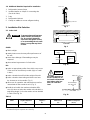
DO:
● select an appropriate position from which every corner
of the room can be uniformly cooled. (High on a wall
is best.)
● select a location that will hold the weight of the unit.
● select a location where tubing and drain hose have
the shortest run to the outside. (Fig. 1)
● allow room for operation and maintenance as well as
unrestricted air flow around the unit. (Fig. 2)
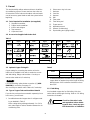
● install the unit within the maximum elevation differ-
ence (H) above or below the outdoor unit and within a
total tubing length (L) from the outdoor unit as detailed
in Table 3 and Fig. 3a.
Table 3
6 inches
min.
6 inches
min.
6 inches min.
Front View
Fig. 2
INDOOR
UNIT
Tubing length (L)
OUTDOOR
UNIT
Elevation
difference (H)
Fig. 3a
Max. Allowable Tubing Limit of Tubing Limit of Elevation Required Amount of
Model Length at Shipment Length (L) Difference (H) Additional Refrigerant
(ft.) (ft.) (ft.) (oz./ft.)*
C2432, CL2432 25 132 50 0.27
WARNING
To prevent abnormal heat gen-
eration and the possibility of
fire, do not place obstacles,
enclosures and grilles in front
of or surrounding the air condi-
tioner in a way that may block
air flow.
* If total tubing length becomes 25 to 132 ft. (max.), additional refrigerant (R22) charge of 0.27 oz./ft. is required.
No additional charge of compressor oil is necessary.
Indoor unit
Floor level
Wall
Minimum height
from floor level
5 ft.
Fig. 3b
For stable operation of
the air conditioner, do
not install wall-mounted
type indoor units less
than 5 ft. from floor
level.
CAUTION
Drain hose
Indoor unit
Outside drainage
Fig. 1
01-386 AirCon 12/11/01 4:48 PM Page 3

4
2-2. Outdoor Unit
AVOID:
● heat sources, exhaust fans, etc. (Fig. 4a)
● damp, humid or uneven locations.
DO:
● choose a place as cool as possible.
● choose a place that is well ventilated.
● allow enough room around the unit for air intake/
exhaust and possible maintenance. (Fig. 4b)
● provide a solid base a minimum of 6 inches above
ground level to reduce humidity and protect the unit
against possible water damage and decreased service
life. (Fig. 5)
● use lug bolts or equal to bolt down unit, to reduce
vibration and noise.
Outdoor unit
Hot air
Heat source
Exhaust fan
Fig. 4a
Min.
1 inch
Min.
1 inch
Min. 2 ft.
Min. 4 inches
Min.
7 ft.
Obstacle above
Ground
Air
dis-
charge
Fig. 4b
Air in
Air in
Air
discharge
Concrete block
4 inch × 1 ft. 4 inch
beams or equal
Anchor bolts
(4 pieces)
Min. 6 inch
Fig. 5
01-386 AirCon 12/11/01 4:48 PM Page 4

5
Indoor
side
Outdoor
side
Set screws for transportation only
Right-rear
tubing
(recommended)
Right tubing
Left-rear tubling
Fig. 6
Fig. 7a
Center of
left-rear
tubing hole
Center of
right-rear
tubing hole
Fig. 7b
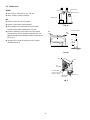
NOTE
Hole should be made at a slight downward slant to the
outdoor side.
In case of left-rear or right-rear tubing
Fig. 8
3. How to Install the Indoor Unit
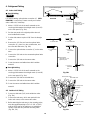
3-1. Remove the Rear Panel from the Unit
Remove and discard the set screws and take off the rear
panel. (Fig. 6)
Tubing can be extended in 3 directions as shown in
Fig. 7a. Select the direction you need providing the
shortest run to the outside unit.
3-2. Make a Hole
(1) Remove the rear panel from the indoor unit and
place it on the wall at the location selected. Make
sure the unit is horizontal, using a carpenter’s level
or tape measure to measure down from the ceiling.
(2) Determine which side of the unit you should make
the hole. (Fig. 7b)
(3) Before making a hole, check carefully that no studs
or pipes are directly run behind the spot to be cut.
The above precautions are also applicable if tubing
goes through the wall in any other location.
(4) Using a sabre saw, key hole saw or hole-cutting drill
attachment, cut a hole in the wall. See Table 4 and
Fig. 8.
Table 4
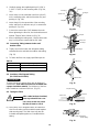
(5) Measure the thickness of the wall from the inside
edge to the outside edge and cut PVC pipe at a
slight angle 1/4" shorter than the thickness of the
wall. (Fig. 9)
(6) Place the plastic cover over the end of the pipe (for
indoor side only) and insert in the wall. (Fig. 10)
NOTE
CAUTION
Also avoid areas where electri-
cal wiring or conduits are
located.
Hole Dia. (inch)
3-3/16"
Plastic cover
(Field Supply)
OUTSIDE
INSIDE
Wall
Slight
angle
PVC pipe
Fig. 10
PVC pipe (locally purchased)
Cut at slight angle
Fig. 9
01-386 AirCon 12/11/01 4:48 PM Page 5

6
3-3. Install the Rear Panel on the Wall
Be sure to confirm that the wall is strong enough to sus-
pend the unit.
See either Item a) or b) below depending on the wall
type.
a) If Wooden Wall
(1) Attach the rear panel to the wall with the 10 screws
provided. (Fig. 11)
If you are not able to line up the holes in the rear
panel with the beam locations marked on the wall,
use toggle bolts to go through the holes on the panel
or drill 3/16 inch dia. holes in the panel over the stud
locations and then mount the rear panel.
(2) Double check with a ruler or carpenter’s level that
the panel is level. This is important to install the unit
properly. (Fig. 12)
(3) Make sure the panel is flush against the wall. Any
space between the wall and unit will cause noise and
vibration.
b) If Block, Brick, Concrete or Similar Type Wall
Make 3/16 inch dia. holes in the wall. Insert rawl plugs
for appropriate mounting screws. (Fig. 13)
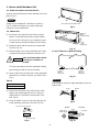
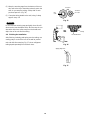
3-4. Remove the Grille to Install the Indoor Unit
Basically, these models can be installed and wired with-
out removing the grille. If access to any internal part is
needed, follow the steps as given below:
How to remove the grille
(1) Set the 2 flaps in the horizontal position.
(2) Unscrew the 3 screws. (Fig. 14a)
(3) Remove the grille.
(a) Hold both corners of the air intake grille, then pull
out and up to open. (Fig. 14b)
(b) Use a standard screwdriver to push up the 3 tabs
to remove the grille. (Fig. 14b)
(c) Pull the lower part of the grille toward you to
remove. (Fig. 14a)
Fig. 11
Fig. 12
3/16 inch
dia. hole
1-3/16 inches or more
Rawl plug
(Field supply)
Fig. 13
Air intake grille
Grille
Fig. 14a
Air intake grille
Fig. 14b
01-386 AirCon 12/11/01 4:48 PM Page 6

7
How to replace the grille
(1) Close the flaps.
(2) Reinstall the grille into the lower part while aligning
its tabs on the upper part. (Fig. 15a) Insert the tabs
in the slots and push the lower part of the grille back
into position.
(3) Press at each of the 5 tabs to completely close the
grille. Make sure that the grille and frame are firmly
fitted together. (Fig. 15b)
3-5. Shape the Indoor Side Tubing
1) Arrangement of tubing by directions
a) Right tubing
The corner of right frame needs to be cut by a
hacksaw or the like. (Fig. 16)
b) Right-rear or left-rear tubing
In this case, the corner of the frame need not be
cut.
2) To mount the indoor unit on the rear panel:
Hang the 3 mounting slots of the unit on the
upper tabs of the rear panel. (Fig. 17)
3-6. Wiring Instructions
General precautions on wiring
1) Before wiring, confirm the rated voltage of the unit as
shown on its nameplate, then carry out the wiring
closely following the wiring diagram.
2) Provide a power outlet to be used exclusively for
each unit, with a power supply disconnect and circuit
breaker for overcurrent protection provided in the
exclusive line.
3) To prevent possible hazard due to insulation failure,
the unit must be grounded.
4) Each wiring connection must be done tightly and in
accordance with the wiring system diagram. Wrong
wiring may cause the unit to misoperate or become
damaged.
5) Do not allow wiring to touch the refrigerant tubing,
compressor, or any moving parts of the fan.
6) Unauthorized changes in the internal wiring can be
very dangerous. The manufacturer will accept no
responsibility for any damage or misoperation that
occurs as a result of such unauthorized changes.
Frame
Right tubing
outlet
Fig. 16
Tab
Mounting slot
Fig. 17
Fig. 15a
Fig. 15b
01-386 AirCon 12/11/01 4:48 PM Page 7

8
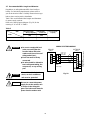
3-7. Recommended Wire Length and Diameter
Regulations on wiring diameter differ from locality to
locality. For field wiring requirements, please refer to
your local electrical codes. Carefully observe these regu-
lations when carrying out the installation.
Table 5 lists recommended wire lengths and diameters
for power supply systems.
Refer to the wiring system diagram (Fig. 18) for the
meaning of “A” and “B” in Table 5.
Table 5
2
4
2
4
11
INDOOR
UNIT
Terminal
OUTDOOR
UNIT
(B)
Terminal
(A)
L2
L1
G
G
G
230V/208V
230V/208V
230V/208V
(Inter-unit)
power line
Grounding line
Grounding
line
Power supply
Single phase 230V/208V 60HZ
Disconnect
switch
Field supply
Fig. 18
WARNING
● Be sure to comply with local
codes on running the wire
from the indoor unit to the
outdoor unit (size of wire and
wiring method, etc.).
● Each wire must be firmly
connected.
● No wire should be allowed to
touch refrigerant tubing, the
compressor, or any moving
part.
CAUTION
Be sure to connect the power
supply line to the outdoor unit
as shown in the wiring dia-
gram. The indoor unit draws its
power from the outdoor unit.
To avoid the risk of electric
shock, each air conditioner
unit must be grounded.
WARNING
#
…
AWG (American Wire Gauge)
WIRING SYSTEM DIAGRAM
AWG
Model
C2432, CL2432 69 (Max.) 164 (Max.) 25A
(A) Power Supply
Wiring Length (ft.)
(B) Inter-Unit
Power Line
Fuse or Circuit
Capacity
(#12)
(#14)
01-386 AirCon 12/11/01 4:49 PM Page 8

9
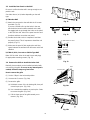
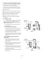
3-8. Wiring Instructions for Inter-unit Connections
(1) Insert the inter-unit wiring (according to local codes)
into the through-the-wall PVC pipe. Run the wiring
toward the indoor side allowing approx. 10 inch to
extend from the wall face. (Fig. 19)
(2) Route the inter-unit wiring from the back of the
indoor unit and pull it toward the front for connection.
(Fig. 20a, 20b)
(3) Connect the inter-unit wiring to the corresponding
terminals on the terminal plate (Fig. 20a, 20b) while
referring to the wiring diagram.
(4) Be sure to secure the wiring with the provided
clamp.
How to remove the cover plate
To access the terminal plate inside the indoor unit, follow
these steps.
(1) Using a Phillips screwdriver, take out the screw on
the cover plate. (Fig. 20a, 20b)
(2) Remove the cover plate.
Rear
panel
Wiring
Wall
10 in.
Plastic
cover
Fig. 19
Terminal
plate
Cover plate
Fig. 20a
Fig. 20b
Lock nut
Top of conduit
connector
Inter-unit
control line
wiring
Earth
plate
01-386 AirCon 12/11/01 4:49 PM Page 9

10
When connecting each power wire to the corresponding
terminal, follow the instructions “How to connect wiring to
the terminal” and fasten the wire securely tight with the
fixing screw of the terminal plate.
How to connect wiring to the terminal
■ For solid core wiring (or F-cable)
(1) Cut the wire end with a cutting pliers, then strip the
insulation to expose the solid wire about 1 inch.
(Fig. 21a)
(2) Using a screwdriver, remove the terminal screw(s)
on the terminal plate.
(3) Using the pliers, bend the solid wire to form a loop
suitable for the terminal screw.
(4) Shape the loop wire properly, place it on the termi-
nal plate and fix it securely with the removed termi-
nal screw using a screwdriver.
■ For stranded wiring
(1) Cut the wire end with a cutting pliers, then strip the
insulation to expose the stranded wiring about 3/8
inch and tightly twist the wire ends. (Figs. 21b and
21c)
(2) Using a screwdriver, remove the terminal screw(s)
on the terminal plate.
(3) Using a ring connector fastener or pliers, securely
clamp each stripped wire end with a ring connector.
(Fig. 21b)
(4) Place the ring connector wire, and replace and tight-
en the removed terminal screw using a screwdriver.
(Fig. 22)
Being careful not to cut the wire, strip off the plastic insu-
lation using a wire cutter or pliers. (Fig. 23)
NOTE
Solid wire
Loop
Insulation
Strip 1 inch
Fig. 21a
Stranded wire
Ring
connector
Strip 3/8 inch
Fig. 21b
Screw with
special washer
Ring connector
Terminal plate
Wire
Fig. 22
Screw with
special washer
Ring
connector
Wire
WARNING
Loose wiring may cause the
terminal to overheat or result
in unit malfunction. A fire haz-
ard may also exist. Therefore,
be sure all wiring is tightly
connected.
Twist wire ends
Fig. 21c
Fig. 23
01-386 AirCon 12/11/01 4:49 PM Page 10

11
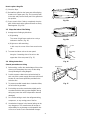
3-9. Mounting
■ Right-side tubing
(1) Shape the refrigerant tubing so that it can easily go
into the wall hole. (Fig. 24)
(2) Push the wiring, refrigerant tubing, and drain hose
through the hole in the wall. Adjust the indoor unit so
it is securely seated on the rear panel.
(3) Carefully bend the tubing (if necessary) to run along
the wall in the direction of the outdoor unit and then
tape as far as the fittings.
(4) Connect the refrigerant tubing to the outdoor unit.
(After performing a leak test on the connecting part,
insulate it with tubing insulation. (Fig. 26)) Also, refer
to Section 4-3. Connecting Tubing between Indoor
and Outdoor Units.
(5) Assemble the refrigerant tubing, drain hose, and
inter-unit wiring as shown in Fig. 27.
Cover
Refrigerant
tubing
Drain hose
Inter-unit
wiring
Fig. 24
Pipe bending tool
a
b
b / a = 0.7 or more
Fig. 25
Insulation
(Field supply)
Fig. 26
Refrigerant tubing
Drain hose
Conduit
Inter-unit wiring
Fig. 27
CAUTION
If using a stepladder, be careful
to keep your balance and not
fall off. To prevent the unit
from damage and avoid per-
sonal injury, ask for someone’s
help when feeding the tubing
through the hole because the
unit is heavy and difficult to
hold in place.
CAUTION
The air conditioner’s perfor-
mance will be deteriorated if a
tube is crushed. To prevent
crushing of the tube, avoid
sharp bends. Use a pipe bend-
ing tool to bend the tube.
(Fig. 25)
01-386 AirCon 12/11/01 4:49 PM Page 11

12
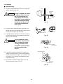
3-10. Drain Hose
a) The drain hose should be slanted downward to the
outdoors. (Fig. 28)
b) Never form a trap in the course of the hose.
c) If the drain hose will run in the room, insulate the
hose with insulation* so that chilled condensation
will not damage furniture or floors. (Fig. 29)
* Foamed polyethylene or its equivalent is recom-
mended.
Slant
Drain
hose
Indoor
unit
Fig. 28
WARNING
Risk of Electric Shock
Do not supply power to the
unit or operate it until all tub-
ing and wiring to the outside
unit are completed.
Condensation
Insulation material
(locally purchased)
must be used.
Fig. 29
01-386 AirCon 12/11/01 4:49 PM Page 12

13
4. Refrigerant Tubing
4-1. Indoor Unit Tubing
■ Rear-left tubing
For rear-left tubing, optional tube connection (C) (APR-
EN46U1B) is necessary. Please consult your nearest
sales outlet or A/C workshop.
1. Make a 3-3/16" hole in the wall, centered on the
crossing point between the triangle marks (A and B)
on the rear panel. (Fig. 30a)
2. Set the rear panel at its original position where it
was installed with screws.
3. Cut the wide tube at a point 4-1/8" from the triangle
mark.
4. Remove the 1/2" flare nut from the optional tube
connection (C), place it on the cut wide tube, and
then flare the wide tube. (Fig. 30b)
5. Connect the optional tube connection (C) to the wide
tube.
6. Connect the 3/4" tube to the connected optional tube
connection.
7. Connect the 3/8" tube to the narrow tube.
8. Cover the narrow and wide tubes with insulation
material.
■ Rear-right tubing
9. Make a 3-3/16" hole in the wall, centered on the
crossing point between the triangle marks (A' and B')
on the rear panel. (Fig. 30a)
10. Connect the 3/4" tube to the wide tube.
11. Connect the 3/8" tube to the narrow tube.
12. Cover the narrow and wide tubes with insulation
material.
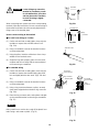
4-2. Outdoor Unit Tubing
1. Connect a wide tube (3/4") to the wide tube valve.
(Fig. 31a)
2. Connect the tube assy, which was packed in the
indoor unit carton, to the narrow tube valve.
3. Before attaching the tube assy to the mounting valve,
wrap the supplied packing A (3/4" × 1-3/8" × T3/16")
onto the 5/16" tube of the tube assy to avoid direct
contact of the tube assy with the mounting valve.
(Fig. 31b, 31c)
Fig. 30b
Fig. 30a
B'
B
A'
2. Mount the rear panel
A
Rear View
Wide tube
Optional tube
connection (C) 1/2"
(Optional part)
1. Cut hole
in wall
3. Cut
4. Flare
5. Connect
4-1/8"
4. Flare wide tube
3. Cut wide tube
5. Connect tube
assy
Optional tube
connection (C) 1/2"
(Optional part)
Narrow
tube 3/8"
6. Connect
wide tube
3/4"
7. Connect
narrow tube
3/8"
Mounting valve
Packing B
Packing A
Clamp
Narrow tube (3/8")
Wide tube (3/4")
Wide tube valve
Narrow tube valve
Tube assy
Fig. 31a
NOTE
01-386 AirCon 12/11/01 4:49 PM Page 13

14
4-3. Connecting Tubing between Indoor and
Outdoor Units
a) Tightly connect the indoor side refrigerant tubing
extended from the wall with the outdoor side tubing.
(Fig. 33)
b) To fasten the flare nuts, apply specified torque as:
Table 6
4-4. Insulation of Refrigerant Tubing
(For C2432 and CL2432)
To prevent heat loss and wet floors due to dripping of
condensation, both tubes must be well insulated with
a proper insulation material. The thickness of the insu-
lation should be a minimum 5/16 inch. (Fig. 35)
4-5. Taping the Tubes
(1) At this time, the 2 refrigerant tubes (and electrical
wire if local codes permit) should be taped together
with armoring tape. The drain hose may also be
included and taped together as 1 bundle with the
tubing.
IMPORTANT
Indoor unit
Outdoor unit
Spanner
Torque wrench
Fig. 33
Insulation
(Field supply)
Fig. 34
4. Similarly arrange the supplied packing B (2-3/8" ×
1-3/16" × T3/16") on the mounting valve. (Fig. 31b,
31c)
5. Insert clamp A in the extracted round hole (
φ
3/16")
on the mounting valve, and bind the tube assy and
packing A. (Fig. 31b)
6. Insert clamp B in the square hole of the mounting
valve, and bind it so the tube assy is in contact with
packing B. (Fig. 31c)
7. Connect the narrow tube (3/8") between the units.
When tightening the flare nut, use the double-wrench
method. (Torque: 300 to 340 lbs.·in) (Fig. 32)
8. After completing the tubing work, check that the tube
assy is not in direct contact with the 3/4" tube.
Tube assy
Narrow tube
Fig. 32
Fig. 31b
Fig. 31c
Tube Dia. Tightening Torque
3/8inch Approx. 300 – 340 lbs.
.
in (35 – 40 N
.
m)
3/4inch Approx. 870 – 1,040 lbs.
.
in (100 – 120 N
.
m)
CAUTION
After a tube has been insulated,
never try to bend it into a nar-
row curve, as this may cause
the tube to break or crack.
Clamp B
Clamp A
Packing B
Packing A
3/16" hole
φ
Clamp B
Clamp A
Square hole
Packing B
Packing A
01-386 AirCon 12/11/01 4:49 PM Page 14

(2) Wrap the armoring tape from the bottom of the out-
door unit to the top of the tubing where it enters the
wall. As you wrap the tubing, overlap half of each
previous tape turn. (Fig. 36)
(3) Clamp the tubing bundle to the wall, using 1 clamp
approx. every 4 ft.
Do not wind the armoring tape too tightly since this will
decrease the heat insulation effect. Also be sure the con-
densation drain hose splits away from the bundle and
drips clear of the unit and the tubing.
4-6. Finishing the Installation
After finishing insulating and taping over the tubing, use
sealing putty to seal off the hole in the wall to prevent
rain and draft from entering. Fig. 37 shows refrigerant
tubing taped separately from the drain hose.
NOTE
Apply putty here
Tubing
Fig. 37
Fig. 36
Clamp
Insulated tubes
Insulation
Min.
5/16"
Thickness:
min. 5/16"
Fig. 35
15
01-386 AirCon 12/11/01 4:49 PM Page 15

16
5. Remote Control Unit Installation Position
The remote control unit can be operated from either a
non-fixed position or a wall-mounted position.
To ensure that the air conditioner operates correctly, do
not install the remote control unit in the following places:
● In direct sunlight
● Behind a curtain or other place where it is covered
● More than 26 ft. (8 m) away from the air conditioner
● In the path of the air conditioner’s airstream
● Where it may become extremely hot or cold
● Where it may be subject to electrical or magnetic
interference
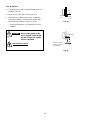
5-1. Mounting on a Wall
1) Confirm the indoor unit beeps when the ON/OFF
button is pressed at the wall location where the
remote control unit is to be attached, then attach the
holder to the wall. (Fig. 38)
2) When taking out the remote control unit, pull it
from the holder.
When using the remote control unit
• Point the transmission portion of the remote con-
trol unit at the receiver area of the indoor unit
when operating the remote control unit, and dur-
ing operation of the air conditioner.
• Do not place objects that may block the transmit-
ted signals between the receiver and the remote
control unit.
When mounting the remote control unit to
prevent theft
1) Mount the holder to the wall with one of the
screws (using only the hole in the top of the
holder) (Fig. 39).
2) Remove the cover of the remote control unit and
take out the batteries. Next, place the remote
control unit in the holder.
3) Fasten both the remote control unit and holder to
the wall with the remaining screw (using the hole
in the bottom of the holder).
4) Install the batteries in the remote control unit and
close the cover.
Truss-head
tapping screw
5/32 × 5/8" (4 × 16mm supplied)
Remote
control
unit holder
Holder
Holder
Truss-head
tapping screw
5/32 × 5/8" (4 × 16mm supplied)
Fig. 39
Fig. 38
01-386 AirCon 12/11/01 4:49 PM Page 16
-
 1
1
-
 2
2
-
 3
3
-
 4
4
-
 5
5
-
 6
6
-
 7
7
-
 8
8
-
 9
9
-
 10
10
-
 11
11
-
 12
12
-
 13
13
-
 14
14
-
 15
15
-
 16
16
-
 17
17


Sanyo CL2432 User manual
- Category
- Split-system air conditioners
- Type
- User manual
Ask a question and I''ll find the answer in the document
Finding information in a document is now easier with AI
Related papers
-
Sanyo Cool Installation Instructions Manual
-
Sanyo CG1411 Installation Instructions Manual
-
-
-
-
-
-
-
-
Other documents
-
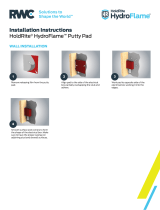 Holdrite HF-PP-2 Installation guide
-
Klimaire KMIR4364E09 Installation guide
-
 CANOPIA 705516 Operating instructions
-
Fujitsu AOUG48LMAS1 Installation guide
-
Turbo Air TAS12V Template
-
Klein Tools J2139NECRN Specification
-
Panasonic CS-MKE18NKU Installation guide
-
-
Friedrich UE10A33B Owner's manual
-
EMI EnviroAir Installation & Operation Manual

