GROHE 40146000 Installation guide
- Category
- Sanitary ware
- Type
- Installation guide
This manual is also suitable for

D
.....1
NL
.....6
PL
.....11
P
.....16
BG
.....21
CN
.....26
GB
.....2
S
.....7
UAE
.....12
TR
.....17
EST
.....22
UA
.....27
F
.....3
DK
.....8
GR
.....13
SK
.....18
LV
.....23
RUS
.....28
E
.....4
N
.....9
CZ
.....14
SLO
.....19
LT
.....24
I
.....5
FIN
...10
H
.....15
HR
.....20
RO
.....25
DESIGN + ENGINEERING
GROHE GERMANY
www.grohe.com
33 870
BRIDGEFORD
99.0036.031/ÄM 228956/07.13
English .....4
Français .....6
Español .....8

I
S.v.p remettre cette instruction à l'utilisateur de la robinetterie!
Entregue estas instrucciones al usario final de la grifería!
Please pass these instructions on to the end user of the fitting!
1
Page is loading ...
Page is loading ...

4
English
Application
Operation is possible in conjunction with:
• Pressurized storage heaters
Operation is not possible with:
• Low-pressure storage heaters (displacement water heaters)
Specifications
• Max. flow: 6.6 L/min or 1.75 gpm/60 psi
• Flow pressure
- min. 7.25 psi
- recommended 14.5 - 72.5 psi
- greater than 72.5 psi, fit pressure reducing valve
• Max. operating pressure 145 psi
• Test pressure 232 psi
• Temperature
- max. (hot water inlet) 158 °F
- thermal disinfection possible
• Water connection: cold - RH hot - LH
• Deck thickness max. 2 3/8"
• Non reversible cartridge
Notes:
- Major pressure differences between cold and hot water
supply should be avoided.
- To be installed according to local codes and regulations.
- This faucet is not intended for the use with portable
appliances.
Installation
Flush piping system prior and after installation of faucet
thoroughly!
Prepare sink faucet
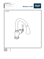
Refer to the dimensional drawing on page 1.
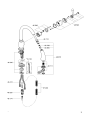
Mount sink faucet, see Fig. [1].
1.Push escutcheon (A) on faucet.
2.Fit O-Ring (B) and insert faucet into sink. Feed the
connection hoses separately through the sink.
3.Push on ring (C) and insert tube (D).
4.Fit brace (E), if necessary, with washer (F) and connect
nut (G) with tube (D). To do this, insert fitting key (H) into
tube (D) and turn fitting key (H) clockwise to fasten faucet.
(Tube may also have to be turned with an 22mm open
ended wrench.)
Note:
If brace (E) is omitted, deck thickness can be increased
by 9/16" to a total of 2 3/8".
The following lever positions can also be obtained, see
Fig. [2].
Connect sink faucet, see Figs. [1] and [3].
- Cold water connection (marked blue) = right
- Hot water connection (marked red) = left
Avoid cross connection. The cartridge is not reversible.
Connect spray hose and spray, see Figs. [4] and [5].
1.Feed the spray hose (I) through the spout (J), see Fig. [4].
2.Feed the spray hose (I) through the faucet body from above
and fit spout (J) so that it snaps into place.
3.Connect the spray (K) with guide ring (K1) to the spray
hose (I).
4.With spray inserted slide on spring (L) onto spray hose (I)
from below, see Fig. [5].
5.Install the snap coupling (M) on the end of the spray
hose (I) and tighten by hand.
6.Pull the sleeve (M1) of the snap coupling (M) downwards
and fit to the union (N).
To ensure that the spray (K) is correctly seated when
inserted, lug (K1) on the spout must engage in recess on the
spray (K2), see Fig. [4].
Open cold and hot water supply and check connections
for leakage!
Operation
1. Lever, see Fig. [6].
2. Spray, see Fig. [7].
Turning off the faucet automatically diverts the water flow from
spray to aerator.
Flow rate limiter
This faucet is fitted out with a flow rate limiter, permitting an
infinitely individual variable reduction of the flow rate. The
highest possible flow rate is set by the plant before despatch.
The use of flow rate limiters in combination with hydraulic
instantaneous water heaters is not recommended.
To activate see “Replacing the cartridge” point 1 to 4,
Figs. [8] and [9].
Maintenance
Inspect and clean all parts, replace as necessary and grease
with special grease.
Shut off cold and hot water supply!
I. Replacing the cartridge, see Fig. [8].
1.Detach cover cap (O) and screw out screw (P1).
2.Pull off lever (P).
3.Remove fixing screw (Q1) and pull off adaptor (Q).
4.Pull off the cap (R).
5.Remove screws (S) and detach complete cartridge (T).
6.Change the complete cartridge (T).
Assemble in reverse order.
Observe the correct installation position!
Make sure that the cartridge seals engage in the grooves
on the housing. Fit screws (S) and tighten evenly and
alternately.
II. Check valve, see Fig. [10].
- Unscrew spray (K) and remove filter (U) and check
valve (V).
III. Strainer and rose, see Fig. [10].
1.Pull out ring (W) and unscrew rose (X) by using wrench (Y).
2.Clean strainer (Z) and rose (X).
Thanks to the SpeedClean nozzles, which must be regularly
cleaned, limescale deposits on the rose can be removed by
simply rubbing with the fingers.
The function of the SpeedClean nozzles is guaranteed for a
period of five years.
Assemble in reverse order.
Replacement parts, see page 2 ( * = special accessories).
Care
Instructions for care of this faucet will be found in the Limited
Warranty supplement.
Page is loading ...
Page is loading ...
Page is loading ...
Page is loading ...
Page is loading ...
Page is loading ...

2014/03/21
www.grohe.com
D
&
+49 571 3989 333
impressum@grohe.de
A
&
+43 1 68060
info-at@grohe.com
AUS
Argent Sydney
&
+(02) 8394 5800
Argent Melbourne
&
+(03) 9682 1231
B
&
+32 16 230660
info.be@grohe.com
BG
&
+359 2 9719959
grohe-bulgaria@grohe.com
CAU
CDN
CH
CN
&
+86 21 63758878
CY
CZ
&
+420 277 004 190
grohe-cz@grohe.com
DK
E
EST
F
&
+33 1 49972900
marketing-fr@grohe.com
FIN
&
+358 10 8201100
teknocalor@teknocalor.fi
GB
GR
&
+30 210 2712908
nsapountzis@ath.forthnet.gr
H
HK
I
IND
IS
J
KZ
LT
LV
&
+372 6616354
grohe@grohe.ee
MAL
&
+1 800 80 6570
info-singapore@grohe.com
N
&
+47 22 072070
grohe@grohe.no
NL
NZ
&
+09/373 4324
P
PL
RI
&
+62 21 2358 4751
info-singapore@grohe.com
RO
&
+40 21 2125050
info-ro@grohe.com
ROK
&
+82 2 559 0790
info-singapore@grohe.com
RP
&
+63 2 8041617
RUS
&
+7 495 9819510
info@grohe.ru
S
SGP
&
+65 6 7385585
info-singapore@grohe.com
SK
T
&
+66 2610 3685
info-singapore@grohe.com
TR
UA
&
+38 44 5375273
info-ua@grohe.com
USA
&
+1 800 4447643
us-customerservice@grohe.com
VN
&
+84 8 5413 6840
info-singapore@grohe.com
BiH
AL
HR
KS
ME
MK
SLO
SRB
&
+385 1 2911470
Eastern Mediterranean,
Middle East - Africa
Area Sales Office:
&
+357 22 465200
IR
OM
UAE YEM
-
 1
1
-
 2
2
-
 3
3
-
 4
4
-
 5
5
-
 6
6
-
 7
7
-
 8
8
-
 9
9
-
 10
10
-
 11
11
-
 12
12


GROHE 40146000 Installation guide
- Category
- Sanitary ware
- Type
- Installation guide
- This manual is also suitable for
Ask a question and I''ll find the answer in the document
Finding information in a document is now easier with AI
in other languages
- français: GROHE 40146000 Guide d'installation
- español: GROHE 40146000 Guía de instalación
Related papers
-
GROHE 30313000 Installation guide
-
-
-
-
-
-
-
GROHE 38505000 User manual
-
-
Other documents
-
IKEA ESSVIK AA-290844-1 User manual
-
-
-
-
-
-
-
-
-