Page is loading ...

MANUAL
IVtodel No,
919,679370
Read the Safety Guidelines
and All Instructions Carefully
Before Operating
• SAFETY GUUDELUNES
ASSEMBLY
OPERATUON
MAUNTENANOE
o TROUBLESNOOTUNG
REPAUR PARTS
SoBd by Sears Canada, inc°, Toroato, Oat, MSB288
MGP°679370A 8/f2/99

TABLE OF CONTENTS
Warranty .................................................... 2
Safety Guidelines ................................... 3-8
Assembly ................................................... 8
Operation ............................................. 9-13
Maintenance ...................................... 13-15
Service Adjustments .............................. 15
Storage ................................................... 15
Troubleshooting ..................................... 16
Parts .................................................. 17-31
EPA Codes ........................................ 32-33
How To Order Parts ................. Back Cover
Frangais
DATE PURCHASED:
MODEL NO:
SERIAL NO:
STORE WHERE PURCHASED:
ADDRESS
CiTY
TELEPHONE:
Record the above information about your unit
so that you will be able to provide it in case
of boss or theft.
HORSE POWER
GASOLINE CAPACITY
OiL CAPACITY
7.5 HP
4 GALLON
30 OZ.
1
MAmNTENANCE AGREEMENT
The Craftsman Warranty, plus a Maintenance Agreement,
provide maximum value for your Sears products. Contact
your nearest Sears store for details.
CUSTOMER RESPONSIBILITIES
Read and observe the safety rules.
Follow a regular schedule in maintaining, caring for and us_
ing your generator.
Follow the instructions under "Customer Responsibilities"
and "Storage" sections of this owner's manual.
FULL ONE YEAR WARRANTY ON CRAFTSMAN GENERATORS
For one year from the date of purchase, when this Craftsman generator is maintained and operated according to the
instructions in this owner's manual, Sears will repair, free of charge, any defect in material and workmanship.
mfyour Craftsman Generator is used for commercial or rental purposes, this warranty applies for only 90 days from the
original date of purchase.
FULL ONE YEAR WARRANTY ON CRAFTSMAN ENGINE
For one year from the date of purchase, when this Craftsman engine is maintained and operated according to the
instructions in this owner's manual, Sears will repair, free of charge, any defect in material and workmanship.
mfyour Craftsman engine is used for commercial or rental purposes, this warranty applies only for 90 days from the date
of purchase. This warranty does not cover: Expendable items such as spark plugs and air filters, which become worn
during normal use.
Repairs necessary because of operator abuse or negligence, including damage resulting from no oil being supplied to
the engine or failure to maintain the equipment according to the instructions contained in this owner's manual, are not
covered under warranty.
WARRANTY SERVmCEmSAVAILABLE BY RETURMNG THE GENERATOR TO THE NEAREST SEARS SERVICE CENTER.
This warranty gives you specific legal rights and you may also have other rights, which vary from PROWNCE TO
PROWNCE.
Sold by Sears Oanada_ |ne,_ Toronto_ Ont,
2 -- ENG

SAFETY GUiDELiNES - DEFiNiTiONS
This manual contains information that
is important for you to know and
understand. This information relates
to protecting YOUR SAFETY and
PREVENTING EQUIPMENT PROB-
LEMS. "Tohelp you recognize this
information, we use the symbols to
the right. Please read the manual and
pay attention to these sections.
I_, DANGER ]
URGENTSAFETYiNFORMATiON=A HAZ=
ARD THATWiLL CAUSESERIOUSiNJURY
ORLOSSOF LIFE.
l _,WARN|NG ]
iMPORTANTSAFETY iNFORI_ATiON =A
HAZARD THAT MIGHT CAUSESERIOUS
iNJURYOR LOSSOF LIFE=
j ,_CAUTION ]
informationfor preventingdamage 1;o
equipmen1:.
l NOTE ]
Informal:ion_a1:you s_ould pay
special atten1:ion1:o.
iMPORTANT SAFETY iNSTRUCTiONS
* SAVE THr=Sr= iNSTRUCTiONS *
When using this product basic precautions should always be followed
including the following:
F_RSKOF ELECTF_OCUTRON AND FRF_E
HAZARD
Attempting to connect generator directly
to the electrical system of any building
structure.
Inadequate electrical grounding of gen-
erator.
WHAT COULD HAPPEN
Back feeding electricity through a
building's electrical system to the
outside utility feed lines could en=
danger repair persons attempting to
restore service.
Attempting to connect to the incoming
utility service could result in electrocu-
tion.
Restoration of electrical service while
the generator is connected to the in-
coming utility could result in a fire or
serious damage if a isolator switch is
not installed.
The failure of one of the generator's
electrical devices, a broken wire, wet
surfaces, etc. could result in the entire
unit becoming electrically charged.
Contact with electrically charged
surfaces could result in electrocution.
HOW TO PREVENT UT
Never back feed electricity through a
structure's electrical system.
To connect to a structure's electrical
system in a safe manner and always
have a Double-Throw Transfer Switch
installed by a qualified electrician, in
compliance with local ordinances.
(When installing a Double-Throw
Transfer Switch, a minimum of 10
gauge wiring must be used.}
Make sure that the unit is connected
to an appropriate electrical ground,
_naccordance with the requirement
of the National Electric Code. See
page 8 for grounding instructions.
3 -- ENG

READ AND UNDERSTAND ALL WARNINGS BEFORE
ATTEMPTING TO OPEP_TE CENEP_TOR.
RBSK OF ELECTROCUTBON AND FBRE={cont'd}
HAZARD
Operation of generator in rain, wet, icy,
or flooded conditions.
Use of worn damaged, undersized or un-
grounded extension cords.
Placing generator on or against highly
conductive surface, such as a steel
walkway or metal roof.
Improper connection of items to gen-
erator.
Operation of unit when damaged, orwith
guards or panels removed.
WHAT COULD HAPPEN
Water is an excellent conductor of
electricity! Water which comes in
contact with electricity charged
components can transmit electricity to
the frame and other surfaces, resulting
in electrical shock to anyone contact-
ing them.
Contact with worn or damaged exten-
sion cords could result in electrocution.
Use of undersize extension cords could
result in overheating of the wires or at-
tached items, resulting in fire.
Use of ungrounded cordsets could pre-
vent operation of circuit breakers and
result in electrical shock.
Accidental leakage of electrical current
could charge conductive surfaces in
contact with the generator.
Exceeding the load capacity of the gen-
erator by attaching too many items, or
items with very high load ratings to it
could result in overheating of some
items or their attachment wiring result-
ing in fire or electrical shock.
Attempting to use the unit when it has
been damaged, or when it is not func-
tioning normally could result in fire or
electrocution.
Removal of guarding could expose elec=
trically charged components and result
in electrocution.
HOW TO PRI:VENT iT
Operate generator in a clean, dry,
well ventilated area. Make sure
hands are dry before touching unit.
Inspect extension cords before use
and replace with new if required.
Use proper size (wire gauge) cordset
for application.
Always use electrically grounded
cordset.
Place generator on low conductivity
surface such as a concrete slab.
Read the load rating chart and in-
structions on page 9, 10 and 11.
Make sure that the summation of
electrical loads for all attachments
does not exceed the load rating of
the generator.
Do not operate generator with me-
chanical or electrical problem. Have
unit repaired by an Authorized Ser-
vice Center.
Do not operate generator with pro-
tective guarding removed.
4 i ENG

READ AN{) UNDERSTAND ALL VARNmNGS BEFORE
ATTEMPTBNG TO OPERATE GENERATOR°
RiSK OF FiRE
HAZARD
Attempting to fill the fuel tank while the
engine is running.
Sparks, fire, hot objects
Improper storage of fuel
Inadequate ventilation for generator
Tampering with factory set engine speed
settings.
Overfilling the fuel tank - fuel spillage.
WHAT COULD HAPPEN
Gasoline and gasoline vapors can
become ignited by coming in contact
with hot components such as the
muffler, engine exhaust gases, or from
an electrical spark.
Cigarettes, sparks, fires, or other hot
objects can cause gasoline or gasoline
vapors to ignite.
Improperly stored fuel could lead to ac-
cidental ignition. Fuel improperly secured
could get into the hands of children or
other unqualified persons.
Materials placed against or near the gen-
erator or operating the generator in ar-
eas where the temperature exceeds 104°
R ambient can interfere with its proper
ventilation features causing overheating
and possible ignition of the materials.
Engine speed has been factory set to
provide safe operation. Tampering with
the engine speed adjustment could re-
suet in overheating of attachments and
could cause a fire.
Spilled fuel and its vapors can become
ignited from hot surfaces or sparks.
HOW TO PREVENTUT
Turn engine off and allow it to cool
before adding fuel to the tank. Equip
area of operation with a fire extin-
guisher certified to handle gasoline
or fuel fires.
Add fuel to tank in well ventilated
area. Make sure there are no sources
of ignition near the generator.
Store fuel in a container designed to
hold gasoline. Store container in se-
cure location to prevent use by oth-
ers.
g_ln a_
well ventilated area a minimum offour
feet from any objects or wall. DO
NOT OPERATE UNtT INDOORS OR
IN ANY CONFINED AREA.
Never attempt to "speedup" the en-
gine to obtain more performance.
Both the output voltage and fre-
quency will be thrown out of stan-
dard by this practice, endangering
attachments and the user.
Use care in filling the tank to avoid
spilling fuel. Make sure fuel cap is
secured tightly and check engine
for fuel leaks before starting
engine. Move generator away from
refueling area or any spillage before
starting engine. Allow for fuel
expansion. Keep maximum fuel
level % inch below the tip of the
fuel tank. Never refuel with the
engine running.
5 -- ENG

READ AN{) UNDERSTAND ALL VARNmNG$ BEFORE
ATTEMPTBNG TO OPERATE GENERATOR.
Risk of injury and
Trans_ Generator
HAZARD
Fire, hhalafion, Damage to Vehicle
Surfaces
Property Damage When
WHAT COULD HAPPEN HOW TD PREVENT iT
Fuel or oil can leak or spill and could
result in fire or breathing hazard, seri-
ous injury or death can resulL Fuel or oil
leaks will damage carpet, paint or other
surfaces in vehicles or traibrs.
If generator is equipped with a fuel
shut-off valve, turn the valve to the
off position before transporting to
avoid fuel leaks, If generator is not
equipped with a fuel shut-off valve,
drain the fuel from tank before trans-
porting. Only transport fuel in an CSA
approved container, Always place
generator on a protective mat when
transporting to protect against dam-
age to vehicle from leaks, Remove
generator from vehicle immediately
upon arrival at your destination
RiSK OF BREATHING - INHALATION HAZARD
HATARD
Gasoline engines produce toxic carbon
monoxide exhaust fumes.
WHAT COULD HAPPI:N
Breathing exhaust fumes will cause se-
rious injury or death.
HOW TO PRr:VENT IT
Operate generator in clean, dry, well
ventilated area. Avoid enclosed ar-
eas like garages, basements, stor-
age sheds, etc, which lack a steady
exchange of air. Never operate unit
in a location occupied by humans or
animals. Keep children, pets and oth-
ers away from area of operating unit.
6 -- ENG

READ AN{) UNDERSTAND ALL WARNmNGS BEFORE
ATTEMPTBNG TO OPERATE GENERATOR°
RiSK OF UNSAFE OPERATION
HAZARD
Operation of generator in careless
manner.
Operation of voltage sensitive appli=
ances without a voltage surge protec-
tor.
WHAT COULD HAPPEN
All sources of energy include the poten-
tial for injury. Unsafe operation or main-
tenance of your generator could lead to
serious injury or death to you or others.
Any gasoline operated household gen-
erator will incur voltage variations caus-
ing damage to voltage sensitive appli-
ances or result in fire.
HOW TO PREVENTUT
o Review and understand all of the
operating instructions and warn-
ings in this manual.
o Become familiarwith the operation
and controls of the generator.
Know how to shut it off quickly.
o Equip area of operation with a fire
extinguisher certified to handle
gasoline or fuel fires.
o Keep children or others away from
the generator at all times.
Always use U.L listed voltage pro-
tector to connect voltage sensitive
appliances (TV, computer, stereo,
etc.). Failure to use a U.L listed volt=
age surge protector will void the war-
ranty on your generator.
Notice: A multiple outlet strip is not
a surge protector make sure you use
a U.L. listed voltage surge protector.
RiSK OF HOT SURFACm=S
HAZARD
Contact with hot engine and generator
components.
WHAT COULD HAPPEN HOW TO PREVENT UT
Contact with hot surfaces, such as em
gines exhaust components, could result
in serious burns.
During operation, touch only the con-
trol surfaces of the generator. Keep
children away from the generator at
all times. They may not be able to
recognize the hazards of this prod-
uct.
RiSK OF MOVING PARTS
HAZARD
Contact with moving parts can result in
serious injury.
WHAT COULD HAPPEN
The generator contains parts which ro-
tate at high speed during operation.
These parts are covered by guarding to
prevent injury.
HOW TO PREVENTiT
Never operate generator with guard-
ing or cover plates removed. Avoid
wearing loose fitting clothing or jew-
elry which could be caught by mov-
ing parts.

READ AND UNDERSTAND ALL WARNINGS BEFORE
ATTEMPTBNG TO OPERATE GENERATOR°
HAZARD
Lifting a very heavy object.
RiSK FROM LiFTiNG
WHAT COULD HAPPEN
Serious injury can result from attempt-
ing to lift too heavy an object.
HOW TO PREVENT iT
The generator istoo heavy to be lifted
by one person. Obtain assistance
from others before you try to move
it.
Read Owner's Manual Do not operate equipment unflHyou have read Owner's ManuaHfor
Safety, _ and Maintenance Instructions,
This product is not equipped with a spark arresting muffHer.If the product will be used around flammable materials, or on
land covered with materials such as agricultural crops, forest, brush, grass, or other similar items, then an approved spark
attester must be installed and is legally required in the state of California. it is a violation of California statutes section
130050 and/or sections 4442 and 4443 of the California Public Resources Code, unless the engine is equipped with a spark
arrestor, as defined in section 4442, and maintained in effective working order. Spark arrestors are also required on some
U.S. Forest Service land and may also be legally required under other statutes and ordinances.
Engine exhaust contains chemicals known, in certain quantities, to cause cancer, birth defects or other reproductive harm.
CARTON CONTENTS
Main Unit
Owner's Manual
Battery Charge Cables
Main Generator Unit
OwnerBs ManuaJ
Battery Charge Cables
CAUTION: Read owner's manual. Do not attemptto
operate equipment until you have read Owner's
Manual for Safety, Operation, and Maintenance In-
structions.
REMOVE GENERATOR FROM CARTON
Open carton from top.
Cut carton along dotted lines.
Remove all carton inserts.
Remove generator through opening in carton.
GROUNDBNG THE GENERATOR
This generator should be grounded to help prevent
accidental electrical shock. Shown below is a picture of
the grounding lug supplied on your generator. First, drive
a 3/4" or 1" diameter copper pipe or rod into the ground
close to the generator set. The pipe must penetrate moist
earth. Using #10 gauge wire, connect one end of the wire
into the grounding lug. Next, connect the other end of the
wire to the copper pipe or rod using an approved ground
clamp.
I}
iMPORTANT: Before any attempt to start your generator
be sure to check engine oil (See OPERATION under
Engine Oil on page 11)
Grounding Lug
8 -- ENG

KNOW YOUR GENERATOR
Read this Owner's IVianual and Safety Rules be_
fore operation of your Generator, Compare this
illustration with your generator to familiarize yourself
with the location of various controls and adjustments.
Save the manual for future references.
FUEL TANK= Capacity of 4 US gallons.
CHOKE SWITCH= Lever used to start cold engine.
ENGINE RUN/STOP SWITCH= Sets engine in starting
mode for recoil starter - Stops running engine.
ENGINE OiL FILL- Place where engine oil is poured.
CiRCUiT BREAKER= Each receptacle has a circuit
breaker to protect the generator from overloading.
120 VOLT DUPLEX RECEPTACLES- Used to supply 1800
watts of electrical power per receptacle for operations.
Protected by 15 amp circuit breaker.
120/240 VOLT TWISTLOCK RECEPTACLE- Used to
supply 1800 watts of electrical power for 120 volt operations
and for 240 volt operation 3750. Wiil only supply 1875 watts
each if both receptacles are being used. Protected by 15
amp circuit breaker.
120 VOLT TWISTLOCK RECEPTACLE- Used to supply
1800 watts of power per receptacle protected by a 15 amp
circuit breaker_
AIF(CLFJ_HER-(nciudes filter element and foam pre-cieaner
that limits the amount of dirt that enters the engine.
FULL POWER SWITCH - Switch used to convert every
receptacle on the panel, when placed in the 120 position,
to a 120 volt receptacle. This wiil allow you to receive the
fuil capacity of the generator by using ail 120 volt recep-
tacles. When in the 120/240 position, you wiil only be able
to use half of the 3750 watts when using the 120 volt recep-
tacles. But in this position, the fuil 3750 watts can be re-
ceived in the 240 twistiock receptacle.
IDLE COHTROL SWITCH- When on, allows the engine to
run at a lower speed when there is no load on the generator.
AiR CLEANI=R
(DLE CONTROL
SW(TCH
FULL
POWER
SWITCH
t 20/240
TWJSTLOCK
RECEPTACLE
t 20 TW|STLOCK
RECEPTACLE
9 -- ENG

Your generator is equipped with dupbx 120 voit receptacb
a 120 twbfiock and a 120/240 voit twisfiock receptacb.
The unit is ariseequipped with a 15 amp circuit breaker for
the dupbx 120 voit receptacbs, a 15 amp circuit breaker
for the 120 voit twistiock receptacb and a 15 amp circuit
breaker for the 120/240 voit twisdock receptacb. If the cir-
cuit breaker trips, unpiug aHebctrbai Headsfrom the gen-
erator. Letthe circuit breaker cooi down. Push circuit breaker
button to reset.
@ @
120V 120/240V 12V1OA DO
OFF ON
120V 15A
(Combined total
from both outlets)
120/30A
240V 20A
or
120V 20A / 120V 20A
FULL POWER SWmTCH
Your Craftsman generator has a full power switch on the
controi panel This switch has two positions: 120 VOLT
ONLY, and 120/240 VOLT.
120 Position
When placed in the 120 position, (Shown below) every re-
ceptacb on the panel will be converted to a 120 volt recep-
tacb. 240-volt power is not available. This position allows
full capacity of the generator to be received by using all
120-volt receptacles. While in the 120 position, each re-
ceptacb has the ability to reach the maximum 4650 surge
wattage for inductive motors that require 4650 watts or be-
low to start.
120V 120/240V
1201240 Position
When in the 120/240 position, (Shown Below) only half of
the 3750 watts carl be received when using the 120-volt
receptacles and the 120/240-volt twistlock receptacle will
be converted to allow the full 3750 watts to be received
from this one receptacle. Also in this position, the 120-volt
receptacles will only reach a maximum of 4650 surge watts.
120V 120/240V
GENERATOR CAPACWY
Exceeding the rated capacity of your generator carl
result in serious damage to your generator and connected
electrical devices. You should observe the following to
prevent overloading the unit:
Starting and running wattage requirements must be
calculated to match your generator wattage capacity.
Resistive load appliances such as light bulbs, TV's
and microwaves, have the same starting and running
wattage. The wattage used for calculating the capacity
can usually be found on each of these appliances.
Some inductive appliances and tools wiii iist on the motor
name plate, the starting and running voltage and amperage
requirements. Use the following formula to convert voltage
and amperage to wattage:
_Volts X Amp = Watts}
Inductive load appliances and tools such as refrigerators,
air compressors and washers require approximately 2 to
4 times the listed running wattage for starting the equip-
ment. This initial load only lasts for a few seconds on
start-up but isvery important when figuring your total
wattage to be used.
NOTE: Always start your largest electric motor first, and
then plug in other items, one at a time.
The guide below is provided to assist you in determining
the appliances and tools that can be ran with the wattage
capacity of your generator.
10 -- ENG

OBTAmNING ELECTRBC_TY FROM
There are basicaiiy two ways to obtain eiectrbity form a
generator:
Use of extension cords directly form the generator
to the appiiance, iights, toois, etc.
Use of a doubie-throw transfer switch instaiied
directly to the main eHectrbaHsuppiy outside of the
house.
Extension Cord
When using an appliance or tool at a considerable distance
from the generator, a 3-wire extension cord that has a 3-
blade grounding plug and 3-dot receptacle that accepts
the tool's plug should be used. A cord of adequate size
must be used. A minimum of 12 gauge wire size with at
least a 20 amp draw can be used. When amperage
exceeds 20 amps a 10 gauge wire size should be used.
Connecting Generator To Main Eleetrieam
SuppJy
Potenfiai hazards exist when a eiectricai generator is con-
nected to the main eiectricai suppiy coming into the house.
It is at that point that the generator couid feed back into the
utiiity company's system causing possibie eiectrocution of
workers who are repairing electrical lines. To avoid back
feeding of electricity into utility systems, a double-threw
transfer switch should be installed between the genera-
tor and utility power. This device should be installed by a
licensed electrician and in compliance with all local electri-
cal codes.
NOTE: When installing a Double-ThrowTransfer Switch,
a minimum of 10 gauge wiring must be used.
CHARGBNG A BATTERY
iMPORTANT: Always use safety glasses, rubber gloves
and protective clothing while charging battery.
Your generator has the capability of recharging a 12-volt
storage or automotive battery. To recharge a 12-volt
battery, proceed as follows:
First, check the fluid level in all of the battery cells.
Add distilled water if necessary. Do not use tap
water,
Clean battery posts if necessary.
Connect battery charge canes to panel receptacle
Start the engine. Let it run while the battery charges.
When the battery is fully charged, stop the engine
and disconnect the battery charge canes from the
panel and battery. Batteries should not be charged
when the unit is unattended.
NOTE- _ llb not use the -_t to c_ any 6_olt _atteries°Ds
not use the unit to crank an engine having a discharged
b_ttey°
BEFORE STARTRNG ENGINE
CAUTION: Always check engine oil level before
every start. Running engine low of oil or out of oil
could result in serious damage to the engine
Automatic BdUeControU
The automatic idle control switch, when inthe ON posi-
tion, allows the engine to run at lower speed when there
is no load on the generator. This wiii lower the engine
noise, save on fuel consumption and engine life. When in
the OFF position the engine wiii run at 3600 RPM's
continuous with or without a load.
ON OFF
m:_L }ON1D EC TRQLL
NOT_=: The idie contrbTmust b-euntSe OFF position when
operating iarge motor ioads (Refrigerators, freezers, etc.) or
voitage sensitive eiectronic equipment (TV,computers, etc.)
Engine OiU
Your unit has been shipped without oii in the engine. A
bottle of SAE 30 weight oii is inciuded in the carton.
Remove oii dip stick iocated on the side of engine. The
oii dip stick is cieariy marked with a iine that teiHsyou
when unit has enough oil Do not firthabove this point
Pour slowly.
CLEAN
Connect the battery charge cane with the red handle
to the battery post indicated by POS or (+).
Connect the battery charge cane with the black
handle to the battery post indicated by NEG or (-).
me crankcase 1the
futur
Service SF, SG, SH" rated SAE 30 weight. Use no special
additives. Select the oil's viscosity grade according to
you expected operating temperatures.
11 -- ENG

$AE Viscesi_y Grades
Air cooled engines run hotter than automotive engines. The
use of multi-viscosity oil such as (10W-30, etc.) in ambient
temperatures above 40°F (4°C) wiii result in higher than
normal oil consumption. If multi-viscosity oil is used, check
the oil level more frequently to prevent any posssible en-
gine damage due to lack or lubrication.
Use of SAES0 oii below 40°F (4°C) wiii result in hard start-
ing and possible engine damage due to inadequate lubri-
cation.
Lew Oil Shutdown
Your Craftsman generator engine is equipped with Low
Oil Shutdown. Low Oil Shutdown is a safetydevice
designed to protect your engine from damage in the
event the oil level in the crankcase is low.
If while the engine is running, the oil gets low, it wiii
automatically shut itself down and wiii not restart until the
oil is added. If the oil is low before start-up, the genera-
tor wiii not start until oil is added.
NOTE: The Low Oil Shutdown mechanism is very sensi-
tive. You must fill the engine to the full mark on the
dipstick to inactivate this safety device.
Gasoline
Your generator engine is 4 cycle. Use unleaded fuel only.
Never mix oil with gasoline.
CAUTION: Never fiii fuel tank completely. Fiii tank to
1/2" below the bottom of the filler neck to provide
space for fuel expansion. Wipe any fuel spillage from
engine and equipment before starting engine.
WARNING: Neverfill fuel tank indoors. Never fill fuel
tank when engine is running or hoL Do not smoke
when filling fuel tank.
Use clean, fresh, regular unleaded gasoline with a mini-
mum of 85 octane. Do not mix oil with gasoline. If unleaded
fuel is not available, leaded fuel may be used.
To Start Your Generater
CAUTION: Never run engine indoors or in enclosed, 1
poor ventilated areas, engine exhaust contains car-
bon monoxide, an ordoriess and deadly gas.
Make sure the fuel shutoff valve isturned to the open posi-
tion.
CLOSE
o Remove gas cap
Add unleaded gasoline, slowly, to fuel tank.
Do not overfiii.
On the engine there is a choke/run lever. Place lever
CHOKE
Throttle is factory seL
ON
Grasp the starter grip and pull slowly until resistance
is felt, then pull firmly to start engine.
o When engine starts, gradually move choke lever to
RUN position.
If engine does not start after 5 pulls, place choke
back to run position.
For hot engine starts make sure choke lever is in
the run position. Make sure fuel shut off valve is open.
12 -- ENG

Cennectin9 Electrical Loads
Let engine run and warm up for about five minutes
Piug in the desired 120 or 240 voits toob.
DO NOT connect 240 volt equipment to the 120 volt
duplex receptacles.
DO NOT connect 3-phase loads to the panel
receptacles.
iMPORTANT; You should always add up the rated
watts of all lights, tools and appliances you are power-
ing at one time. This total should not exceed the rated
capacity of your generator or circuit breaker rating of
the receptacle supplying power.
Steppin9 The Engine
Disconnect all electrical loads.
Switch the start/off switch to the off position.
iMPORTANT: Never store engine with fuel in tank,
indoors, or in enclosed, poorly ventilated areas or where
fuel fumes may reach an open flame.
CUSTOMER RESPONSBBBLBTBES TABLE
MAINTNENANCE TASK
Before each
use
Every 25
Hours of Every
Season
Every 50
Hours of Every
Season
Check oil leve! X See Note 2
Change oil X See Note 1
Clean Air Filter Assembly X
Check Spark Plug X
Prepare Unit for Storage
Every i00
Hours of Every
Season
x
Prepare unit for storage if it is to remain idmefor more than 30 days,
Note 1: Change oil after first two (2)operating hours and every 50 operating hours thereafter, more often if operated in
extreme dusty or dirty conditions.
Note 2: Check oil after 5 hours of operation (See page 14 - ENGINE MAINTENANCE - Changing Engine Oil.)
13 -- ENG

GENERAL RECOMMENDATBON$
The warranty of the generator does not cover items that
have been subjected to operator abuse or negHigence. To
receive full vaHuefrom the warranty, operator must maintain
the generator as instructed in this manual
Some adjustments will need to be made periodically to
maintaining your generator.
GENERATOR MAINTENANCE
Your generator shouHd be kept dean and dry at aHtimes.
The generator shouHd not be stored or operated in
enviroments that incHudesexcessive moisture, dust or any
corrosive vapors. Ifthese substances are on the generator,
dean with a cloth or soft bristHebrush. Do not use a garden
hose or anything with water pressure to cHeanthe genera-
tor. Water may enter the cooling air slots and could possi-
bly damage the rotor, stator and the internal windings of the
gen head.
All adjustments in the Maintenance section of this manual
should be made at least once each season.
ENGINE MAINTENANCE
Changing Engine Oim
For a new engine, change oil after the first 5 hours of
operation. Thereafter, change oil after every 50 hours of
operation.
Change the oil while the engine is still warm. The oil will
flow freely and carry away more impurities. Make sure the
engine is level when filling, checking, or changing oil.
Change the oil as follows:
To keep dirt, grass clippings, etc., out of the engine,
clean the area around the drain plug and dipstick
before removing it.
Remove the oil drain plug and dipstick. Tilt the engine
slightly towards the oil drain to obtain better drainage.
Be sure to allow ample time for complete drainage.
Reinstall the drain plug. Make sure it is tightened
securely.
Fill the crankcase with new oil of the proper type, to
the Full mark on the dipstick. Always check the level
with the dipstick before adding more oil.
Reinstall the oil fill cap or plug and tighten securely.
FULL_
Service Air Cleaner
NOTE: Do not use petroleum solvents, e.g., kerosene,
which will cause the cartridge to deteriorate. Do not use
pressurized air to clean cartridge. Pressurized air can
damage the cartridge.
To service air cleaner follow these steps:
1. Unscrew cover screws. Remove cover and air
cleaner assembly.
2. Remove cartridge from cover, then retainer
(if equipped) and pre-deaner.
To service pre-deaner, wash in liquid detergent and
water. Squeeze dry in a clean cloth. Saturate in engine
oil. Squeeze in clean, absorbent cloth to remove all
excess oil. Replace if very dirty or damaged.
To service cartridge, clean by tapping gently on a flat
surface. Do not oil cartridge. Replace if dirty or dam-
aged.
3. Reassemble pre-deaner or retainer (if equipped.)
Place in cover with pre-cleaner mesh side toward
cartridge. Place cartridge in retainer in cover.
4. Push cover and air cleaner assembly squarely onto
base (tabs must be in slots, if equipped) and hold
firmly. Tighten cover screws securely.
Do not clean engine with a forceful spray of water
because water could contaminate fuel system. With
a brush or cloth clean finger guard after every use to
prevent engine damage caused by overheating.
14 -- ENG

Before running engine, clean muffler area to remove all
combustible debris.
Clean and Replace Spark Plug
Change the spark plug every 100 hours of operation or
once each year, whichever comes firsL This will help
your engine to start easier and run better.
RESISTOR
Carburetor
The carburetor of your generator is pre-set at the factory.
The carburetor should not be tampered with. if your gen-
erator is used at an altitude in excess of 4000 feet perfor-
mance may be affected. If so consult with your nearest
Sears Service Center regarding high altitude set changes.
GovePnoP
Your engine governor maintains the constant operating
speed of your generator. DO NOT tamper with the engine
governor which is factory set for proper engine speed.
Over-speeding your engine above factory high speed set-
ting can be dangerous and couUd possibly cause personal
injury or property damage. If you believe the engine is run-
ning too fast or slow, take your generator to a Authorized
Sears Service Center for repair and adjustment.
CAUTION: Low engine speeds impose a heavy load
on the engine and when sufficient power is not avail-
able the engine life could be shorten.
Ifyou are going to store your generator for more than 30
days, use the following information as a guide to prepare
the generator for storage.
STORAGE BNSTRUCTBONS
CAUTION: Never store generator with fuel in the
tank indoors or in enclosed, poorly ventilated areas,
where fumes can reach an open flame, spark or pilot
light as on a furnace, water heater clothes dryer or
other gas appliances.
Engine Preparation
Add fuel stabilizer to fuel tank to minimize the
formation of fuel gum deposits during storage.
Run engine at bast 10 minutes after adding stabilizer
to allow it to enter the fuel system.
Next shut off engine.
Disconnect the spark plug wire and remove the
spark plug.
Add one teaspoon of oii through the spark piug hob.
Place rag over spark plug hole and pull the recoil a
few times to lubricate the combustion chamber.
Replace the spark plug, but do not connect the spark
plug wire.
NOTE: If a fuel stabilizer is not used, all gasoline must
be drained from the tank and carburetor to prevent gum
deposits from forming on these parts and causing
possible malfunction of the engine.
Generator
Clean the generator as outlined on Page 14 (Generator
Maintenanc@
Check that cooiing air dots and openings on generator
are open and unobstructed.
15 -- ENG

Engine will not start
No electrical output
Repeated circu# breaker tripping
Generator overheating
No auto idle
DC does not have power with the
circuit breaker depressed
1. Low on fuel or oil.
2. Ignition switch in "Off" position.
3. Faulty spark plug.
4. Choke in wrong position.
5. Fuel shut-off valve in closed
position.
6. Unit loaded during start-up.
7. Spark plug wireloose.
1. Faulty receptacle.
2. Circuit breaker kicked out.
3. Defective capacitor.
4. Faulty powercord.
5. GFCI switch breaker kicked out (if
equipped)
1. Overload
2. Faulty cords or equipment.
1. Generator overloaded.
2. Insufficient ventilation.
1. Faulty solenoid
2. Faulty idle control switch
3. Faulty windings in stator
4. Faulty circuit board
5. Faulty wire harness
1. Faulty rectifier
2. Faulty windings in stator
3. Faulty wire harness
CORRECTION
1. Add fuel or oii.
2. Turn to "ON" position
3. Replace spark plug.
4. Adjust chokeaccordingiy.
5. Open fuel shut-off valve.
6, Removeload from unit,
7, Attach wire to spark plug,
1, Have Service Center replace,
2, Depress and reset,
3, Have Service Center replace
capacitor,
4, Repair or replace cord,
5. Depress and reset
,
2.
Reduce load.
Check for damaged, bare, or
frayed wires on equipment.
Replace.
1. Reduce load.
2. Move to adequate supply of
fresh air.
1. Have Service Center replace.
2. Have Service Center replace.
3. Have Service Center replace.
4. Have Service Center replace.
5. Have Service Center replace
1. Have Service Center replace.
2. Have Service Center replace.
3. Have Service Center replace.
16 -- ENG

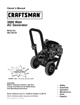
CRAFTSMAN3750 WATT GENERATOR 919,679370
10
13
LJE20-25 IN-LB:
5 7 8
6 TORQUE 120-144 IN-LBS
4
TORQUE 96-120 IN-LBS
2
TORQUE 60-70 IN-LBS
12
11
KEY
NO,
1
2
3
4
5
6
7
8
9
lO
11
12
13
DESCRiPTiON
HEATSHELD
SCREW, 1/4-20 x .75
FUELCLAMP
SCREW, 5/16-18 X 1.25
WASHER
NUT, HEX WIZ LOCK
WASHER, LOCK
GROUND STRAP
CAP SCREW,5/16-18 X 3A
FUEL TANK (4 GALLON)
ENGHNE
WASHER,=875OD =35HD=083THK
FUEL TANK CAP
PART NUMBER
GS-816
91895680
GS-0227
SSF-605
SSN-60-ZN
SSF-8150
SSN-1619-ZN
GS-0118
SS-12-SD
GS-0650
GS-0665
SSN-632
GS-0443
17 -- ENG

CRAFTSMAN3750 WATT GENERATOR 919o679370
'\
\
\
L_%_14
TORQUE 20-25 mN-LBS
14
15
16
17
18
19
2O
21
22
23
24
FUEL HOSE
DRAHNCOCK GROMMET
FRAME ASSEMBLY
GENERATOR ASSEMBLY
GROUND LUG
SCREW, HEX WASHER, UNSLOTTED
VIBRATION ISOLATOR
VIBRATION ISOLATOR
SCREW, 10-24 x 9/16
DRAIN COCK
END COVER
GS-0225
GS-0446
G8-0611
GS-0672
GS-0117
SSF-928
GS-0033
GS-0433
SSF-553-1
GS-0437
GS-0077
18 -- ENG

CRAFTSMAN3750 WATT GENERATOR 919,679370
\
SHOWN FOR REFERENCE ONLY
26
27
28
3O
34
35
36
37
38
29
32
33
25
24
SHOWN FOR REFERENCE ONLY
KEY
NO,
24
25
26
27
28
29
30
31
32
33
34
35
36
37
38
39
DESCRiPTiON
RECTiFiER
SCREW, 10-24 X .75 T25 TORX
DRIVE ENDADAPTER
LOCK WASHER 3/8
CAP SCREW, 3/8-16 X 1
ROTOR ASSEM BLY
STATORTHRU BOLT
STATORASSEMBLY
W/ASHER 11/16 OD X 11/32
NUT,5/16-24
ROTOR THRU BOLT
BEARING SUPPORT
HEX NUT %-20
CAPACITOR
CAPACITOR BRACKET
SCREW 10-32
ITEMS NOT SHOWN
*Diode(s) --
PART NUMBER
GS-0767
SSF-3158-1
GS-0830
SSN-619
SSF-577
GS-0588
GS-0110
GS-0673
SS-6506-CD
SSF-576
GS-0091-1
GS-0793
SSF-575
GS-0748
GS-0595
SSF-553-1
GS-0082
19 -- ENG

CRAFTSMAN3750 WATT GENERATOR 919,679370
KEY
NO,
4O
41
42
43
44
45
46
47
48
49
5O
51
52
53
DESCRiPTiON
SCREW, 10-9 x .50 PLASTITE
SCREW, #6-32 X .5TORX
SPEED NUT #6-32
RECEPTACLE, 120V DUPLEX
RECEPTACLE, 3 PRONG TWISTLOCK
RECEPTACLE, 4 PRONG TWISTLOCK
FULL POWER SWITCH
IDLE CONTROL SWITCH
15A CiRCUiT BREAKER
10A CIRCUIT BREAKER
SWITCH FACE PLATE
CiRCUiT BOARD FOR BDLECONTROL SWITCH
JAM NUT 7,116
WASH ER3/8
RESISTOR ASS_I D.C. SHUNT
PART NUMBER
SSF-3156
SSF-583
SSF-584
GS-0804
GS-0021
GS-0445
GS-0045
GS-0679
GS-0024
GS-0681
GS-0207
GS-0663
SSF-595
SS-1525-CD
GS-0835
*Not Shown
20 -- ENG
/