Page is loading ...

ORION
10707 Stancliff Road
Houston, Texas 77099
Phone: (281) 933-7673
www.rose.com
KVM Switch Cross-point Switch


LIMITED WARRANTY
Copyright Rose Electronics 2013. All rights reserved.
No part of this manual may be reproduced, stored in a retrieval system, or transcribed in any form or any means, electronic or mechanical, including photocopying and
recording, without the prior written permission of Rose Electronics.
Rose Electronics Part # MAN-OR-SR
Printed In the United States of America – Rev 1.5
Rose Electronics warrants the Orion™ to be in good working order for one year from the date of purchase from Rose
Electronics or an authorized dealer. Should this product fail to be in good working order at any time during this one-
year warranty period, Rose Electronics will, at its option, repair or replace the Unit as set forth below. Repair parts
and replacement units will be either reconditioned or new. All replaced parts become the property of Rose
Electronics. This limited warranty does not include service to repair damage to the Unit resulting from accident,
disaster, abuse, or unauthorized modification of the Unit, including static discharge and power surges.
Limited Warranty service may be obtained by delivering this unit during the one-year warranty period to Rose
Electronics or an authorized repair center providing a proof of purchase date. If this Unit is delivered by mail, you
agree to insure the Unit or assume the risk of loss or damage in transit, to prepay shipping charges to the warranty
service location, and to use the original shipping container or its equivalent. You must call for a return authorization
number first. Under no circumstances will a unit be accepted without a return authorization number. Contact an
authorized repair center or Rose Electronics for further information.
ALL EXPRESS AND IMPLIED WARRANTIES FOR THIS PRODUCT INCLUDING THE WARRANTIES OF
MERCHANTABILITY AND FITNESS FOR A PARTICULAR PURPOSE, ARE LIMITED IN DURATION TO A PERIOD
OF ONE YEAR FROM THE DATE OF PURCHASE, AND NO WARRANTIES, WHETHER EXPRESS OR IMPLIED,
WILL APPLY AFTER THIS PERIOD. SOME STATES DO NOT ALLOW LIMITATIONS ON HOW LONG AN IMPLIED
WARRANTY LASTS, SO THE ABOVE LIMITATION MAY NOT APPLY TO YOU.
IF THIS PRODUCT IS NOT IN GOOD WORKING ORDER AS WARRANTED ABOVE, YOUR SOLE REMEDY
SHALL BE REPLACEMENT OR REPAIR AS PROVIDED ABOVE. IN NO EVENT WILL ROSE ELECTRONICS BE
LIABLE TO YOU FOR ANY DAMAGES INCLUDING ANY LOST PROFITS, LOST SAVINGS OR OTHER
INCIDENTAL OR CONSEQUENTIAL DAMAGES ARISING OUT OF THE USE OF OR THE INABILITY TO USE
SUCH PRODUCT, EVEN IF ROSE ELECTRONICS OR AN AUTHORIZED DEALER HAS BEEN ADVISED OF THE
POSSIBILITY OF SUCH DAMAGES, OR FOR ANY CLAIM BY ANY OTHER PARTY.
SOME STATES DO NOT ALLOW THE EXCLUSION OR LIMITATION OF INCIDENTAL OR CONSEQUENTIAL
DAMAGES FOR CONSUMER PRODUCTS, SO THE ABOVE MAY NOT APPLY TO YOU. THIS WARRANTY
GIVES YOU SPECIFIC LEGAL RIGHTS AND YOU MAY ALSO HAVE OTHER RIGHTS WHICH MAY VARY FROM
STATE TO STATE.
IBM ®, AT, and PS/2 are trademarks of International Business Machines Corp.
Microsoft ® and Microsoft Windows™ are registered trademarks of Microsoft Corp.
Apple, Macintosh, and ADB are trademarks of Apple Computer, Inc.
Sun is a registered trademark of Sun Microsystems Inc.
Any other trademarks mentioned in this manual are acknowledged to be the property of the trademark owner

EUROPEAN UNION DECLARATION OF CONFORMITY
This is to certify that, when installed and used according to the instructions in this
manual, together with the specified cables and the maximum CPU- cable length <3m,
the Units:
List on page 2 – 5
are shielded against the generation of radio interferences in accordance with the
application of Council Directive 89/336/EEC as well as these standards:
EN 55022: 1999 Class A
EN 55024: 1999
IEC 61000-4-2: 2001
IEC 61000-4-3: 2001
IEC 61000-4-4: 2001
EN 61000-3-2 2001
EN 61000-3-3 2002
The device was tested in a typical configuration with CPU.
This equipment has been found to comply with the limits for a Class A digital device,
pursuant to Part 15 of the FCC Rules. These limits are designed to provide reasonable
protection against harmful interference when the equipment is operated in a commercial
environment. This equipment generates, uses, and can radiate radio frequency energy and, if
not installed and used in accordance with the instruction manual, may cause harmful
interference to radio communications. Operation of this equipment in a residential area is
likely to cause harmful interference in which case the user will be required to correct the
interference at his own expense.

TABLE OF CONTENTS
Contents Page #
Disclaimer ........................................................................................................................................................................ 1
Introduction ...................................................................................................................................................................... 1
Crosspoint Switch mode .............................................................................................................................................. 1
KVM Switch mode ....................................................................................................................................................... 1
About This Manual .......................................................................................................................................................... 2
Features ....................................................................................................................................................................... 2
Compatibility ................................................................................................................................................................ 3
DDC Information .......................................................................................................................................................... 3
Selecting the moment of switching to next frame ........................................................................................................ 3
Selection of Color reduction for transfer acceleration ................................................................................................. 3
Package contents ........................................................................................................................................................ 3
Product registration ...................................................................................................................................................... 3
System Overview ............................................................................................................................................................ 4
Synchronized switching ................................................................................................................................................... 4
Orion Model Description .................................................................................................................................................. 5
KVM Switch Installation ................................................................................................................................................... 6
Powering Up the System ............................................................................................................................................. 7
Configuration menus .................................................................................................................................................... 7
Keyboard Control: ........................................................................................................................................................ 7
On-screen-Displays ..................................................................................................................................................... 7
Menu ........................................................................................................................................................................ 7
Login Menu .............................................................................................................................................................. 8
Configuration Menu .................................................................................................................................................. 8
Configure open menu............................................................................................................................................... 9
Configure system menu ......................................................................................................................................... 10
Touch Screen settings ........................................................................................................................................... 13
Configure user ........................................................................................................................................................ 14
User Matrix Configuration ...................................................................................................................................... 15
CON Port Configuration ......................................................................................................................................... 16
CON Matrix Configuration ...................................................................................................................................... 18
CPU Port Configuration.......................................................................................................................................... 19
Status Information ...................................................................................................................................................... 20
Status Display – CON ports ................................................................................................................................... 20
Status Display – CPU ports ................................................................................................................................... 21
Status Display – Network ....................................................................................................................................... 22
Status Display – Firmware ..................................................................................................................................... 22
Diagnostic LEDs (CATx cable / Fiber cable) ............................................................................................................. 22
Operating the Orion Unit ............................................................................................................................................... 23
HOT Key switching .................................................................................................................................................... 23
OSD / KVM mode switching ...................................................................................................................................... 23
KVM-List mask switching ........................................................................................................................................... 23
Keyboard Commands ............................................................................................................................................ 24
KVM-Switch mask switching ...................................................................................................................................... 25
Keyboard Commands ............................................................................................................................................ 26
Follow-Me function ................................................................................................................................................. 26
Keyboard Commands (Follow-Me mode) .............................................................................................................. 27
Cross Point Switch Mode (CON mask) ......................................................................................................................... 28
Keyboard Commands: ........................................................................................................................................... 29
Cross Point Switch Mode (CPU mask) ......................................................................................................................... 30
Keyboard Commands: ........................................................................................................................................... 30
Switching using a Browser / Web Interface ................................................................................................................... 31
Switching using a Serial Interface ................................................................................................................................. 31
Operating modes - Overview ......................................................................................................................................... 32
Single-Head KVM switch mode ................................................................................................................................. 32
Dual-Head KVM switch mode .................................................................................................................................... 33
Quad - Head KVM switch mode ................................................................................................................................ 34
Single - Head KVM switch / USB 2.0 mode .............................................................................................................. 35
Devices with serial/audio option ................................................................................................................................ 36
Serial Interface – Handling Multiple Serial Devices ................................................................................................... 36
Audio Interface - Setup and Operation ...................................................................................................................... 36

Audio Interface – Using a Microphone ...................................................................................................................... 36
Service Information ....................................................................................................................................................... 37
Maintenance and Repair ........................................................................................................................................... 37
Technical Support ...................................................................................................................................................... 37
Troubleshooting ............................................................................................................................................................ 40
Troubleshooting - Monitor .......................................................................................................................................... 40
Troubleshooting – USB Keyboard / Mouse ............................................................................................................... 40
Figures Page #
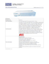
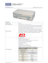
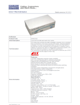
Figure 1. Orion Models .................................................................................................................................................... 5
Figure 2. Typical KVM Switch Configuration ................................................................................................................... 6
Figure 3. OSD Main Menu .............................................................................................................................................. 7
Figure 4. Login OSD ....................................................................................................................................................... 8
Figure 5. Configuration menu.......................................................................................................................................... 8
Figure 6. Open configuration file menu ........................................................................................................................... 9
Figure 7. Configure System menu ................................................................................................................................ 10
Figure 8. Touch screen calibration ................................................................................................................................ 13
Figure 9. Configure User menu ..................................................................................................................................... 14
Figure 10. User Matrix Menu ......................................................................................................................................... 15
Figure 11. CON port configuration ................................................................................................................................ 17
Figure 12. CON Matrix Configuration ............................................................................................................................ 18
Figure 13. CPU Port Configuration ............................................................................................................................... 19
Figure 14. Status menu ................................................................................................................................................. 20
Figure 15. Status - CON ports .................................................................................................................................... 20
Figure 16. Status – CPU Ports ...................................................................................................................................... 21
Figure 17. KVM-List menu ............................................................................................................................................ 24
Figure 18. KVM-switch mask ........................................................................................................................................ 25
Figure 19. Follow Me mask ........................................................................................................................................... 26
Figure 20. Crosspoint Switch menu (CON Mask) ......................................................................................................... 28
Figure 21. Crosspoint Switch menu (CPU Mask) ......................................................................................................... 30
Appendices Page #
Appendix A – General Specifications ............................................................................................................................ 41
Appendix B – Part numbers .......................................................................................................................................... 42
Appendix C – DDC / Color depth set-up (Local Unit) ................................................................................................... 43
Appendix D – Serial switching commands .................................................................................................................... 45
Appendix E – Programming Macros ............................................................................................................................. 48
Appendix F – Cascading units ...................................................................................................................................... 50
Appendix G – Synchronize Switching ........................................................................................................................... 51
Appendix H – Change Initialization command .............................................................................................................. 53

INTRODUCTION
Orion Installation and Operations Manual
1
Disclaimer
While every precaution has been taken in the preparation of this manual, the manufacturer assumes no responsibility
for errors or omissions. Neither does the manufacturer assume any liability for damages resulting from the use of the
information contained herein. The manufacturer reserves the right to change the specifications, functions, circuitry of
the product, and manual content at any time without notice.
The manufacturer cannot accept liability for damages due to misuse of the product or other circumstances outside
the manufacturer’s control. The manufacturer will not be responsible for any loss, damage, or injury arising directly
or indirectly from the use of this product.
(See limited warranty)
Introduction
Thank you for choosing Rose Electronics
Orion ™ System. The Orion System is the results of Rose Electronics
commitment to providing continued state-of-the-art switching solutions for today’s demanding workplace. The Orion
System has proven to be a valuable investment for all types of businesses that have the need to monitor, maintain,
route, switch and access information from multiple computer systems. Its use in large computer and multimedia
facilities gives the IT professional the added flexibility to monitor and maintain all systems, running on different
platforms, from one or multiple KVM stations. The Orion System is the common sense solution that provides the
flexibility, expandability, and security required for today’s business environment.
Rose Electronics' Orion System is designed to configure to whatever your system demands are, one user or multiple
users, two computers or hundreds. All configurations offer standard features that allow for easy, secure, and
complete access to as many computers as your system has from one or multiple KVM user stations. CATx or fiber
cabling is used to connect the computers and user stations to the Orion unit. Using CATx cabling the distance can
be up to 450 feet (140m), using singlemode 9µ fiber cabling, the distance can be up to 6 miles (10,000m). This
greatly reduces the cable bulk and makes installation easier, quicker, and less expensive.
The convenient on-screen display (OSD) menus are intuitive and easy to use. The menus guide you through the
configuration process, making it easy to configure the Orion.
The Orion is used along with an extender transmitter and receiver. The transmitter connects to your computer or
video source and the receiver connects to your DVI monitor, USB keyboard and USB mouse. The transmitter and
receiver units connect to the Orion unit using CATx or fiber cabling. The transmitter and receiver models will vary
depending on the application.
The Orion can be configured to function as a Crosspoint switch or a KVM switch. An additional feature allow the
Orion to be set-up in the “Follow Me” mode. An overview of each configuration mode is described below. See the
appropriate manual section for a detailed description of the installation, configuration, and operating procedure for
each mode.
Reliability, security, versatility, and other advanced technological features ensure the Orion System will streamline
your data center or server room, simplify the maintenance, access and updating of your systems, and easily expand
as your system demands increase.
Crosspoint Switch mode
The Crosspoint switch mode allows you to switch one or more video outputs (16) to any or all video inputs (32). The
Crosspoint switch menu makes connecting and switching easy. Select the monitor to display the video source on,
select the computer to switch to the selected display and press the space bar. Instantly the computer’s video is
displayed on the remote monitors.
KVM Switch mode
The KVM switch mode can be set-up to function as: a 16 user to 32 single head CPUs, 8 user to 16 dual head, or 4
user to 8 quad head CPU KVM switch and also two additional unique features, “Partner” viewing and the “Follow Me”
feature. Partner viewing allows for the distribution of the main display content to one or more remote displays. The
“Follow Me” feature shows your actions on other displays, even changing sources.

2
Orion Installation and Operations Manual
About This Manual
This manual covers the installation, configuration, and the operation of the Orion System. The Orion System
consists of three components; the Orion unit, the extender transmitter(s), and the extender receiver(s). Each
component of the Orion system is described in this manual. The Installation section for each mode describes how all
components are interconnected to form a seamless switching network. The Operations section for each mode
defines how to operate the system and all the user features available to make switching and maintenance simple and
easy.
Features
The Orion can be configured as:
A single head KVM Switch (32 CPUs / 16 User stations (Cascadable to 1024 sources)
A dual head KVM Switch (16 CPUs / 8 user stations)
A quad head KVM switch (8 CPUs / 4 user stations) or
A Crosspoint switch (32 video source inputs / 16 video outputs)
Supports all DVI-D Graphic cards
DVI-D video resolution up to:
1920 x 1200 @ 60 Hz (Single Link)
Supports:
USB keyboard and USB mouse*
CATx or fiber cabling (Multimode and Singlemode fiber)
USB 2.0
Bidirectional audio
Serial interface
16 / 24 Bit auto-switching or 24 Bit color depth (selectable)
CATx and fiber connector modules can be mixed within a single unit.
Extended distances:
CATx cable – 460 feet (140m)
Multimode 50µ – 1,300 feet (400m)
Multimode 62.5µ - 656 feet (200m)
Singlemode 9µ - 32,800 feet ( 10,000m)
Access via On Screen Display, serial, web-based GUI, or hotkey commands
LED indicators for power and link status
Dual power supply option
Rack mountable
* Orion KVM standard devices with USB-HID connectors support the extension of the keyboard and mouse ONLY;
use with other HID devices (Human Interface Device) such as touch screens, graphics tablets, barcode readers or
similar USB devices may be successful – but there is no guarantee for this! The Orion™ KVM standard device is
NOT suitable for use with other USB devices such as scanners, web-cams, data sticks etc.
Orion KVM standard devices support only two USB devices simultaneously, keyboard and mouse or keyboard and
touch-screen, etc. but not keyboard, mouse and touch-screen simultaneously. You can extend by a USB hub but
this does not raise the number of supported devices.

Orion Installation and Operations Manual
3
Compatibility
Video Digital (DVI-D): Digital Video standard installed by DDWG - R, G, B, and CLOCK in a data stream
with up to 3x 1.6 Gbit/sec. Signals are TMDS level.
Keyboard
Compatible with all standard USB keyboards. Certain keyboards with enhanced features may also
be supported with custom firmware. Keyboards with a built-in hub are also supported – but there are
never more than two HID devices supported.
Mouse
Compatible with all standard USB 2-button, 3-button and wheel mice.
CATx / Fiber
The Orion Switch may be equipped with both CATx GBICs and fiber GBICs.
Cables This allows both fiber and CATx Signals to be switched with one Unit.
NOTE: Switching must be from a CATx source to a CATx destination and Fiber source
to a Fiber destination. CATx to Fiber or Fiber to CATx is NOT possible.
Fiber
Supports singlemode (9µ) and multimode (50µ and 62.5µ) cables.
DDC Information
Normally, it is not necessary to make any adjustments to the Orion KVM/ Media device. However, in some
circumstances, it may be necessary to redefine the source of DDC information for the CPU. By default, the unit
uses its own internal DDC table. If this setting does not satisfy your requirements, the DDC table can either be
switched to the DDC table of the locally attached screen or can be downloaded from the remotely located screen and
stored in the internal DDC table. The default is to download the DDC table from the remote monitor.
(See appendix C for instructions on how to modify the DDC setup)
Selecting the moment of switching to next frame
The transmission of screen data is not synchronous to the screen changes of the graphic card. Normally, the
transmission is terminated during the display of a frame on the screen (at the remote unit). If the device switches to
the new frame during the displaying period of the old frame (somewhere on the screen), it is possible that you will
see horizontal screen breaks at the moment of switching (default). On the other hand, if the device idles until the
actual frame is displayed completely (until VSYNC) then the number of frames per second transmitted may be
reduced.
(See appendix C for instructions on changing the switching behavior)
Selection of Color reduction for transfer acceleration
You can select, whether always 24 Bit colors (=full color depth) are transmitted or whether the compression algorithm
automatically switches between 16 and 24 Bit colors to accelerate the data transfer (default). Normally the difference
between 24 Bit and 16 Bit is not recognizable but under some special circumstances e.g. in photo processing
installations there might be disturbing color abbreviations. While the automatic color switching enhances the number
of frames, transmitted per second, fixed 24 Bit color depth gives smooth color grades under all circumstances.
(See appendix C for instructions on how to select the desired mode)
Package contents
Orion unit as ordered
Rack mount kit (with screws)
Power cord(s)
Manual CD
Product registration
Register your product for future updates at: www.rose.com/htm/online-registrationform.htm

OVERVIEW
4
Orion Installation and Operations Manual
System Overview
The Orion system consists of the main Orion unit configured with the CPU and CON modules for your application
(CATx or Fiber). Each CPU port connects to a CATx or Fiber transmitter using a CATx or fiber cable.
Each CON port connects to a CATx or Fiber receiver using a CATx or fiber cable.
The versatility of the Orion unit makes it easily
adaptable to your system environment. It can
be configured for a KVM switch where each
user can connect and control any connected
computer.
In the KVM switch mode, a unique feature
called “Partner Viewing” allows a console user
to share the active display content on one or
more displays.
Another feature is the “Follow Me” feature.
This allows other displays to follow every action
made by the console user.
In the Crosspoint switch mode, up to 32 video
sources can be switched to 16 video outputs.
You can switch a video source to 1 output or
16 outputs.
Each CPU input and CON output must connect
to an extender transmitter and extender
receiver. Rose Electronics offers a wide variety
of transmitters and matching receivers to
handle your specific application:
Single, dual, and quad head DVI-D video
models
Local access models
Serial and audio models
CATx or Fiber models
4x USB 2.0 transparent ports for compatible
USB 2.0 peripherals
The installation, configuration, and operation
for each of the different modes are explained in
the appropriate manual section for the
application the Orion unit is going to be
configured for.
Synchronized switching
The Orion unit can be set-up to control the switching features of other Orion units. When the master unit is switched
to a selected CPU port, all other Orion units configured for synchronization will also switch to that CPU port. The
main unit is assigned a unique IP address compatible with the existing network. The main unit is then connected to
the network via a network cable. The master unit’s IP address is entered into the secondary units that will be
switched via the main unit. See Appendix G for installation and OSD configuration instructions.
Fiber CATx
Transmitter Transmitter
Fiber CATx
Receiver Receiver

MODELS
Orion Installation and Operations Manual
5
Orion Model Description
FRONT VIEW
All models
REAR VIEW
Connectors
CATx
modules
Fiber
modules
CATx / Fiber
modules
1 or 2 IEC320
power inputs
32-RJ45F Inputs
16-RJ45F Outputs
1-RJ11F Network
1-RS232 Serial
1-USB Type B
1 or 2 IEC320
power inputs
32-Fiber LC type
Inputs
16-Fiber LC type
outputs
1-RJ11F Network
1-RS232 Serial
1-USB Type B
Figure 1. Orion Models
NOTE:
Models that have mixed CATx and Fiber modules should be used with care. A CATx CONx KVM station can not
connect to a fiber CPUx port or a fiber CONx KVM station can not connect to a CATx CPUx port. Remember,
connect only CATx to CATx and Fiber to Fiber.
Catx modules
(Singlemode or Multimode fiber modules)
CATx and Fiber modules

INSTALLATION
6
Orion Installation and Operations Manual
The installation section of this manual is divided into a section for the KVM Switch installation and for the Cross-Point
Switch installation procedures. Please turn to the section needed for your application.
KVM Switch Installation
As a KVM Switch the device supports several operation modes:
(See appendix F for cascading configuration example)
16 User ports and 32 CPU ports for Single-Head access
8 User ports and 16 CPU ports for Dual-Head access
4 User ports and 8 CPU ports for Quad-Head access.
Single, Dual, and Quad CPUs and User ports may also be operated in mixed mode.
The maximum number of User ports depends on the detailed configuration.
A maximum of 32 CPUs (up to 10 km away using fiber cable) can be connected to the
Unit via Local transmitter units installed at each CPU.
Up to 16 remote user stations (up to 10 km away using fiber cable) can be connected
to the Orion unit via remote receiver units installed at each console.
The installation of the local transmitter(s) and remote
receivers(s) will vary depending on the needed
application. (Single head, dual head, or quad head KVM
switch, serial and audio options, etc.)
Basic transmitter installation:
(Each connected computer must be connected to a KVM
transmitter and each remote KVM user station must be
connected to a KVM receiver)
1. Connect the DVI video connector(s) from the
computer to the transmitter using a DVI-I MM cable.
2. Connect a USB cable (Type A to Type B) from the
computer’s USB Type A connector to the
transmitters USB Type B connector.
3. If the transmitter has the serial and audio options,
connect these ports to the transmitter using
standard stereo audio cables (MM) for the speaker
and microphone connectors and a DB9 serial cable
from the computer to the transmitter.
4. Connect a CATx or Fiber cable (depending on the
model – up to 32 cables) from the transmitter’s port
to the corresponding CPU port on the Orion unit.
Basic receiver installation:
1. Connect the DVI-I video monitor’s cable to the
corresponding connector on the receiver
2. Connect the USB keyboard and USB mouse to the
keyboard and mouse USB ports on the receiver
3. If the receiver has the serial and audio options,
connect a speaker set to the speaker connector and
a microphone to the Mic input connector.
5. Connect a CATx or Fiber cable (depending on the
model – up to 16 cables) from the receiver’s port to
the corresponding CON port on the Orion unit.
NOTE: If you Orion unit has a mixture of CATx and Fiber
modules, care should be taken to only connect a CATx
connected user station to a CATx connected computer or
a Fiber connected user station to a fiber connected
computer.
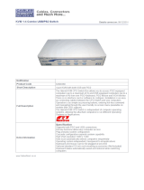
Figure 2. Typical KVM Switch Configuration
Transmitter(s)
up to 32
Receiver(s)
up to 16
Fiber
or
CATx
Fiber
or
CATx

Orion Installation and Operations Manual
7
Powering Up the System
Apply power to the Orion unit, the receivers, transmitters, KVM monitors and all connected computers.
Once all equipment is fully powered up, the system can be used to switch from any user station to any
connected computer.
Configuration menus
The configuration of the Orion unit is easily done using the On-Screen menus. To display the menu system, enter the
key sequence <Shift>+ <Shift>+ <O> (Letter “o”), The “KVM List” Mask is displayed full screen (If the Option
“Listview” is not active, the “KVM Switch” Mask will display instead)
Exit the “KVM List” Mask, if needed, by hitting <ESC> and the “Menu” will displayed full screen as shown below.
Keyboard Control:
To navigate within any OSD menu, use the following key sequences:
<Cursor left> only inside an Input field or Switch Mask
<Cursor right> only inside an Input field or Switch Mask
<Cursor up> Line up (with wrap around) in Input fields or Switch Mask,
Line up (without wrap around) in Menus
<Cursor down> Line down (with wrap around) in Input fields or Switch Mask,
Line down (without wrap around) in Menus
<Page up> Page up in Input-/Status Masks with several pages
<Page down> Page down in Input-/Status Masks with several pages
<Tab> – Next field in Input Masks
<Shift> + <Tab> Previous field in Input Masks
<+> Next Option in Select fields
<-> Previous Option in Select fields
<SPACE> Switch in selection fields with two options only (On/Off or No/Yes)
Only if “Allow Sharing“ is active: Apply and save data in Mask “KVM Switch“
<RETURN> Apply and save data – in Input Masks Select option – in Menus
<ESC> Cancel data input without saving
On-screen-Displays
Menu
Figure 3. OSD Main Menu

8
Orion Installation and Operations Manual
Using the up and down arrow keys, select (highlight) “Configuration” and press enter. If you are not logged on to the
system as the “Administrator”, the LOGIN dialog menu will display requesting a userID and Password.
Login Menu
The factory default settings for the “Login” OSD are:
User – admin
(User and Password are case sensitive)
Password – admin
If these settings have not been changed, enter the
default User and Password in the appropriate field and
click on “Okay”
Upon validation, the “Configuration” menu will display as
shown in figure 5.
Figure 4. Login OSD
Configuration Menu
Figure 5. Configuration menu
Using the up and down arrow keys, select “Open” and press enter. The option allows you to load a previously
saved switch configuration. Up to 8 user defined switch configurations plus the default settings can be saved
within the unit.
Use the up down arrow keys or the mouse to select the configuration scheme to apply and press enter.
Figure 6 shows the “Open Configuration” screen.

Orion Installation and Operations Manual
9
Configure open menu
Figure 6. Open configuration file menu
From the main menu, select “System” and press enter to display the system menu. From this menu you can
set-up the system, access control, switch settings, and mouse settings. Figure 7 shows this menu.

10
Orion Installation and Operations Manual
Configure system menu
Figure 7. Configure System menu
System options
Field
Selection
Description
Name
16 Char.
(Input) Configuration name.
Used for saving the current configuration to file.
Device
16 Char.
(Input) Device name
(displayed in all menus at the lower left)
Info.
64 Char.
(Input) Detailed information about the current configuration
Sub Matrix
Y/N
Y – This switch is configured according to a master switch and remotely controlled
No configuration possible.
N – No slave mode
Load Default
Y/N
Y – Upon “Power On” or “Restart” the switch will boot with the Default
configuration.
N – Upon “Power On” or “Restart” the switch will boot with the last configuration.
Auto Save
Y/N
Y – Switch saves periodically the current configuration into flash.
N – No automatic saving
Enable
COM Echo
Y/N
Y – Switch sends echoes of all performed switch commands
N – No Echoes.
Lock
COM Ports
Y/N
Y – While an OSD is open, all commands via external interfaces are rejected
(LAN, serial).
N – No rejection
Baud rate
kBaud
Numerical
Value
Select a predefined Baud rate for the serial control port (default: 115.2 kBaud)
Slave Matrix
Y/N
Y - Allows a second Orion unit to automatically be switched to the same port as
the master unit
N – No synchronization
Master Address
IP Address
Assigned master unit IP address that secondary units will synchronize to.
(Entered on secondary unit’s OSD)

Orion Installation and Operations Manual
11
Access Options
Field
Selection
Description
Enable Login
Y/N
Y – Login required to access the OSD with user name and password. After login,
the user will remain logged in until he explicitly logs out or an Auto Logout
has been performed. KVM Switching with Hot Keys requires the user to be
logged in.
N – No Login required.
User Matrix
Y/N
Y – User access restricted to CPU’s explicitly unlocked in the User
Matrix. User matrix mode requires user login and implies
“Enable Login“ = “Y“. KVM Switching with Hot Keys requires the user to
be logged in.
N – User Matrix disabled.
CON Matrix.
Y/N
Y – CON Port connectivity restricted to CPU’s explicitly unlocked in
the CON Matrix
N – CON Matrix disabled
Auto
Disconnect
Y/N
Y – Only active if “Enable Login“ or “„User Matrix“ are activated:
CON Port is disconnected from current CPU Port upon entering
into the OSD.
N – Current Connection is held
OSD Timeout
sec
### – Time of inactivity, after which OSD is closed automatically.
0 sec – No Timeout.
Auto Logout
min
### – Time of inactivity, after which the user at this console is logged
out from OSD access automatically.
0 min – Immediate Logout from OSD after closing the OSD.

12
Orion Installation and Operations Manual
Switch Options
Field
Selection
Description
Allow Sharing
Y/N
Y – User may connect to any unlocked CPU with Video Access Only.
NOTE: Switch with <space> Key, no <Return>.
Force
Connect
Y/N
Y – User may connect to any unlocked CPU with full control forcing
any previous user to Video Access only.
Note: Switch with <Return> Key.
N – No Force Connect.
Force
Disconnect
Y/N
Y – User may connect to any unlocked CPU with full control. Previous user is
disconnected.
Note: Switch with <Return> Key.
N – No Force Disconnect.
KVM
Listview
Y – OSD is opened with Menu “KVM List“ (default)
(Dynamic display of available CPU Ports).
N – OSD is opened with Menu “KVM Switch“
(Static display of available CPU Ports)..
KVM Auto Close
Y/N
Y – Immediate exit from OSD after switching CPU Port in Menu “KVM List“
or “KVM Switch“ with immediate display of the new CPU.
N – No Auto Close
Auto Connect
Y/N
Y – If no active CPU connection exists, pressing any console key creates a
connection to the first available CPU.
N – No Auto Connect
CON Timeout
min
### – Time of inactivity, after which the console will be disconnected from a
current CPU connection
Keyboard
Connect
Y/N
Y – When connected to a CPU currently controlled by another console, attempt
to take keyboard control after Release Time seconds of inactivity by the
other console
N – No attempt to gain keyboard control on a shared CPU
Mouse Connect
Y/N
Y – When connected to a CPU currently controlled by another console, attempt
to gain mouse control after Release Time seconds of inactivity by the
other console
N – No attempt to gain mouse control on a shared CPU
Release Time
sec
### – Time of inactivity, after which a console’s keyboard and mouse control of
a CPU connection can be gained by other consoles connected to the
same CPU
Mouse Options
Field
Selection
Description
Hor. Speed 1/x
VAL2
Setting up the horizontal mouse speed
Ver. Speed 1/x
VAL2
Setting up the vertical mouse speed
Double Click
ms
Setting up the time frame for “Double Click” (100 – 800 ms)
Keyboard Layout
Region
Set the OSD keyboard layout according to the keyboard in use
Single Click
Y/N
Y – Execute OSD commands with a single click (when using a touch screen to
control the OSD).
N – Single click inactive
NOTE: Mouse settings are CON Port specific and can be adjusted for each CON Port separately.
NOTE: If “Allow sharing” is activated, the current user of a CPU will not note if
other users gain video access to his CPU.

Orion Installation and Operations Manual
13
Touch Screen settings
The Orion OSD supports touch screens.
NOTE: USB HID based Touch Screen protocols are supported.
Support of Vendor specific protocols only upon request.
To configure the touch screen feature, from the configure System menu, press the <F1> key. The touch screen
calibration window will display as shown in figure 8.
Figure 8. Touch screen calibration
On the touch screen calibration display, touch the upper left of the screen twice, then at the lower right.
test the calibration results and cancel or save the calibration.
This calibration is CON Port specific and must be repeated for each touch screen at its CON Port.
Touch Control
Control by touch is mostly similar to mouse control. Confirmation of a selection is performed by a second touch
instead of double click.

14
Orion Installation and Operations Manual
Configure user
To configure the users of the Orion switch, select the option “User” in the “Configuration” menu by using the cursor
buttons and press enter. ⇒ The “User” mask will display full screen as shown in figure 9.
Figure 9. Configure User menu
In this menu, you can setup user names and privileges.
Field
Type
Description
Name
CHR16
User Name (case-sensitive)
Password
CHR16
User Password (case-sensitive)
HTP
Y/N
User may login and access via HTTP
FTP
Y/N
User may login and access via FTP
PPP
Y/N
User may login and access via ‚Internet’ (not available)
TEL
Y/N
User may login and access via Telnet
POW
Y/N
User is ‚Power-User’ and may activate e.g. the CrossPoint Mode
ADM
Y/N
User is Administrator and may change the configuration or
activate the CrossPoint Mode
/