NOTICE: This service data sheet is intended for use by persons
having electrical and mechanical training and a level of knowledge
of these subjects generally considered acceptable in the appliance
repair trade. The manufacturer cannot be responsible, nor assume
any liability, for injury or damage of any kind arising from the use of
this data sheet.
IMPORTANT NOTE: This unit includes an EOC (electronic oven
control). This board is not eld-repairable.
SAFE SERVICING PRACTICES
To avoid the possibility of personal injury and/or property damage, it is
important that safe servicing practices be observed. The following are
some, but not all, examples of safe practices.
1. Do not attempt a product repair if you have any doubts as to your
ability to complete it in a safe and satisfactory manner.
2. Before servicing or moving an appliance, remove power cord
from electric outlet, trip circuit breaker to Off, or remove fuse.
3. Never interfere with the proper installation of any safety device.
4. Use only replacement parts specied for this appliance. Substitu-
tions may not comply with safety standards set for home appli-
ances.
5. Grounding: The standard color coding for safety ground wires is
green or green with yellow stripes. Ground leads are not to be
used as current carrying conductors. It is extremely important
that the service technician reestablish all safety grounds prior
to completion of service. Failure to do so will create a potential
hazard.
6. Prior to returning the product to service, ensure that:
• All electric connections are correct and secure.
• All electrical leads are properly dressed and secured away
from sharp edges, high-temperature components, and mov-
ing parts.
• All uninsulated electrical terminals, connectors, heaters, etc.
are adequately spaced away from all metal parts and panels.
• All safety grounds (both internal and external) are correctly
and securely reassembled.
• All panels are properly and securely reassembled.
IMPORTANT
DO NOT REMOVE THIS BAG
OR DESTROY THE CONTENTS
WIRING DIAGRAMS AND SERVICE
INFORMATION ENCLOSED
REPLACE CONTENTS IN BAG
p/n A04967801 EN Rev A (15/10)
SERVICE DATA SHEET
Gas Wall Oven with ES100/105 Electronic Oven Control
OVEN CALIBRATION
Set the electronic oven control for normal baking at 350°F. Allow oven
to preheat to set temperature. Obtain an average oven temperature
after a minimum of ve cycles. Press the STOP key to end the Bake
mode.
ADJUSTING THE OVEN TEMPERATURE
1. Press & hold the BAKE key pad and release after the display
shows the factory temperature setting of 00.
Note: If the oven temperature has been previously adjusted from
the factory setting, the current temperature adjusted value will
appear in the display instead.
2. You may increase the oven temperature in 5°F increments with
each press of the UP ARROW key pad to a maximum oven
adjustment of +35°F. You may also adjust the oven temperature
downward in 5°F increments with each press of the DOWN AR-
ROW key pad (total range of -35 to +35). Note: Your oven control
was factory set in the (Fahrenheit) °F Temperature Display Mode.
To change for (Celsius) °C, see Changing the Temperature
Display Mode in the Oven Control Functions section of this Use &
Care Manual.
3. If no other key pad is pressed after 5 seconds the display will
begin to ash.
4. If you do not want to keep the display adjustment, press the
STOP key pad before the oven control beeps. This will cancel the
temperature adjustment procedure. To start this procedure over
again begin with step 1 above OR;
5. If you want to keep the adjustment, wait until the display quits
ashing and the oven control beeps once.
6. The oven temperature adjustment has be accepted by the oven
control and the display will return to the time of day.
Notes: The oven temperature adjustment may be made if your oven
control has been set to operate in the (Celsius) °C Temperature
Display Mode. In this case, each press of the UP ARROW or DOWN
ARROW key will adjust in 1°C increments upward (maximum +18°C)
or downward (maximum -18°C), depending on which arrow key pad is
pressed.
Data Sheet Abbreviations and Terminology
DLB - Double Line Break PS - Power supply board (PS1, PS2, etc)
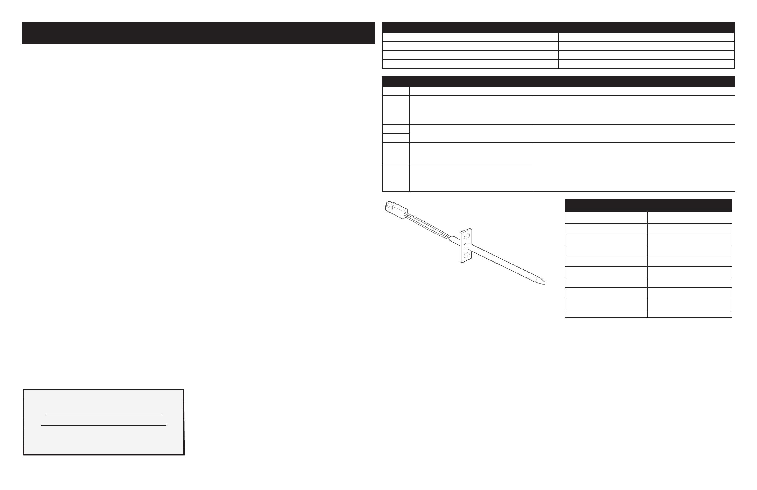
EOC - Electronic Oven Control RTD - Resistance Temperature Detector/Oven Probe
LED - Light-Emitting Diode TCO - Thermal cut out, also “thermo disc” or “thermal limiter”
MDL - Motor Door Latch VSC - Variable Speed Control
Resistance (ohms)
1000 ± 4.0
1091 ± 5.3
1453 ± 8.9
1654 ± 10.8
1852 ± 13.5
2047 ± 15.8
2237 ± 18.5
2697 ± 24.4
Open circuit/infinite resistance
RTD SCALE
Temperature °F (°C)
32 ± 1.9 (0 ± 1.0)
75 ± 2.5 (24 ± 1.3)
250 ± 4.4 (121 ± 2.4)
350 ± 5.4 (177 ± 3.0)
450 ± 6.9 (232 ± 3.8)
550 ± 8.2 (288 ± 4.5)
650 ± 9.6 (343 ± 5.3)
900 ± 13.6 (482 ±7.5)
Probe circuit to case ground
Resistance Temperature Detector
Electronic Oven Control (EOC) Fault Code Descriptions
Code Condition / Cause Suggested Corrective Action
F10 Runaway temperature Check RTD Sensor Probe & replace if necessary. If oven is overheating, discon-
nect power. If oven continues to overheat when the power is reapplied, replace
EOC. Severe overheating may require the entire oven to be replaced should
damage be extensive.
F11 Shorted keypad
Bad EEPROM identication or checksum error
1. Disconnect power, wait 30 seconds and reapply power.
2. If fault returns upon power-up, replace EOC.
F13
F30 Open probe connection 1. Check resistance at room temperature & compare to RTD Sensor re-
sistance chart. If resistance does not match the RTD chart replace RTD
Sensor Probe. Check Sensor wiring harness between EOC & Sensor Probe
connector
2. Check resistance at room temperature, if less than 500 ohms, replace RTD
Sensor Probe. Check for shorted Sensor Probe harness between EOC &
Probe connector.
F31 Shorted probe connection


