Page is loading ...

STOP!
STOP!
Call Us First!
DO NOT RETURN TO STORE.
For immediate help with assembly or product information
call our toll-free number:
or email:
customerservice@backyardproductsllc.com
Our staff is ready to provide assistance.
April through October M - F 8:00 AM to 7:00 PM EST
Saturday 8:30 AM to 4:30 PM EST
November through March M - F 8:00 AM to 5:00 PM EST
1-888-827-9056
16712-GN

(This page intentionally left blank.)

12/17/2013
KEEP THIS MANUAL FOR FUTURE REFERENCE
ASSEMBLY MANUAL
PERGOLA 10' x 12' (305 x 366 cm)
16712-GN
BEFORE YOU BEGIN
IMPORTANT!
READ INSTRUCTIONS THOROUGHLY PRIOR TO BEGINNING ASSEMBLY.
- CUSTOMER SERVICE -
Call: 1-888-827-9056 email: customerservice@backyardproductsllc.com
• BUILDING RESTRICTIONS AND APPROVALS
Be sure to check with local building department and homeowners association for speci c restrictions and/ or requirements before building.
• ENGINEERED DRAWINGS
Contact our Customer Service Team if engineered drawings are needed to pull local permits.
• SURFACE PREPARATION
To ensure proper assembly you must build your pergola on a level surface.
• CHECK ALL PARTS
Inventory all parts listed on pages 3. Contact our Customer Service Team if any parts are missing or damaged.
• LEVELING AND ANCHORING
You may choose to anchor your pergola. See page 5 for optional methods of leveling and anchoring your pergola.

2
FINISH
TOOLS
Safety! Always use approved safety glasses during assembly.
OptionalRequired
HELPFUL REMINDER SYMBOLS
Look for these symbols for helpful reminders throughout this manual.
ORIENT LUMBER FOR BEST APPEARANCE
= Assistance Required; two or more people.
= Ensure squareness.
= Important required step or operation.
= Helpful assembly hint.
= Mark part with pencil.
= Beginning of steps for assembly or installation.
= You have fi nished the assembly or installation.
= Level
❑ Gloves
❑ Dremel
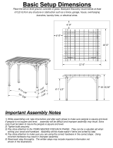
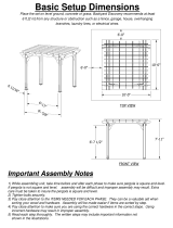
Always install the material leaving the best edge and best surface visible. Please remember that these blemishes in no way
negatively affect the strength or integrity of our product.
(See Fig. A)
❑ Safety Glasses
❑ Tape Measure
❑ Ladder
❑ Hammer
❑ Level
BEGIN
❑ Pencil
❑ Drill / Driver
❑ #2 Philips Drive Bit
❑ #2 Square Drive Bit (Included)
❑ Tool Belt/
Nail Pouch
❑ Square
or
❑ 1/8" Drill Bit
Orient blemishes
to face inward and
away from visibility.
Fig. A

3
PARTS IDENTIFICATION AND SIZES
POSTS RAFTERS
PARTS LIST
INVENTORY YOUR PARTS before you begin.
We suggest sorting parts by the category they are listed in.
x4
3-3/8 x 3-3/8 x 14" (8,6 x 8,6 x 35,6 cm)
x30
J
M
N
L
K
E
D
O
G
H
F
x4
x4
x8
x8
x4
x8
x8
x8
1-3/8 x 3-3/8 x 39-11/16" (3,5 x 8,6 x 100,8 cm)
1-3/8 x 5-3/8 x 162" (3,5 x 13,7 x 411,5 cm)
1 x 4-3/4 x 4-3/4" (2,5 x 12,1 x 12,1 cm)
7/8 x 3-3/8 x 11-7/8" (2,2 x 8,6 x 30,2 cm)
7/8 x 5-3/8 x 90-1/2" (2,2 x 13,7 x 229,9 cm)
3-3/8 x 3-3/8 x 37" (8,6 x 8,6 x 94 cm)
3/4 x 1-1/2 x 37" (1,9 x 3,8 x 94 cm)
3-3/8 x 3-3/8 x 103-1/2" (8,6 x 8,6 x 262,9 cm)
1-3/8 x 5-3/8 x 138" (3,5 x 13,7 x 350,5 cm)
x20
1-3/8 x 3-3/8 x 8-1/2" (3,5 x 8,6 x 21,6 cm)
FASTENER/HARDWARE BAG
x80
x8
x270
x8
x70
x8
3" (7,6 cm)
2" (5,1 cm)
2-1/2" (6,4 cm)
3-1/2” (8,9 cm)
3/8” (1,0 cm)
3/8” (1,0 cm)
Sandpaper
Micro-Shade
Concentrate
x1 x1

4
G
K
J
H
F
E
L
O
M
N
D
PERGOLA ANATOMY
CARE AND MAINTENANCE
142-13/16"
362,7 cm)
120"
304,8 cm)
109-3/4"
(278,8 cm)
132-1/16"
(335,4 cm)
INSIDE
POST
INSIDE
POST
OUTSIDE
POST
OUTSIDE
POST
❑ The wood in your pergola has been treated with a process called ProWood Micro for resistance to fungal decay and
insect infestation.
❑ The color of your pergola is from a process called MicroShade ™ and involves adding pigment into the wood as it is
pressure treated. This process results in colorant throughout the wood which helps minimize surface markings being
visible. The appearance of your pergola with MicroShade will last about two years with no stain application. Over time
the color of the pergola wood will slightly darken.
❑ If you want, you may apply a water repellent which will benefi t the wood and help minimize splitting, checking and
surface cracking.
❑ Checking, splitting and surface cracking are characteristics of all wooden structures. This is caused by varying
seasonal temperatures and moisture conditions. To minimize this checking and/or cracking you may coat your pergola
with a water repellent.
❑ A wood stain may be applied to your pergola if you choose.
❑ For minor touch-up we have included sandpaper and some MicroShade concentrate. Refer to page 26 of this manual
for our suggested procedure for minor touch-up.
❑ We suggest you inspect all hardware and fasteners used to assemble your pergola for any deterioration or looseness.
Re-tighten hardware as required.
90-1/2"
229,9 cm)

5
Concrete Anchor
On-Grade Leveling Method
Check anchoring methods with your local building department.
Gravel for drainage
Solid
Masonry block
Concrete/Wood Deck Anchor
Concrete/Wood Deck Anchor
LEVELING AND ANCHORING OPTIONS
There are multiple ways to anchor your Pergola. A few methods are shown below.
Anchoring materials are not included in this kit.
137-7/16"
(349,1 cm)
MEASUREMENT TO CENTER OF
CORNER POSTS
114-7/8"
(291,8 cm)

6
PARTS REQUIRED:
BEGIN
1
2
3
Place one 138” long rafter as shown with the angled end downward.
YOU WILL MARK ONE RAFTER FIRST!
RAFTERS
Measure and mark locations at top of rafter as shown (Fig. A).
Align all J rafters fl ush at ends. Using a square, use previously marked rafter to mark
ALL EIGHT rafters consistently on top edge (Fig. B).
J
x8
1-3/8 x 5-3/8 x 138" (3,5 x 13,7 x 350,5 cm)
J
NOTE:
Angle down
ALL MARKS
Flush
Flush
Fig. B
Fig. A
16-1/4”
(41,3 cm)
21-1/4”
(54 cm)
41-3/8”
(105,1 cm)
46-3/8”
(117,8 cm)
66-1/2”
(168,9 cm)
71-1/2”
(181,6 cm)
91-5/8”
(232,7 cm)
96-5/8”
(245,4 cm)
116-3/4”
(296,5 cm)
121-3/4”
(309,2 cm)

7
4
5
Orient two J rafters as shown on fl at surface with angled edge down.
RAFTERS
J
x2
1-3/8 x 5-3/8 x 138" (3,5 x 13,7 x 350,5 cm)
L
x20
1-3/8 x 3-3/8 x 8-1/2" (3,5 x 8,6 x 21,6 cm)
Flush
(2) 3" (7,6 cm) Screws
PARTS REQUIRED:
J x2
J x2
Fig. A
Fig. B
Fig. C
Flush
L x20
Center rafter ends L on marks and fl ush to top as shown (Fig. B, C).
Pre-drill 1/8" (0,3 cm) holes through rafter at marks.
Secure rafter ends fl ush to top of rafter using two 3" screws per rafter end.
Marks holes on face of rafter centered on marks as shown (Fig. A).
6
7
FINISH
8
3" (7,6 cm)
x40
3/4" (1,9 cm)
2" (5,1 cm)
Centered
on marks.
Center
on marks.
1/8" (0,3 cm)
Drill Bit
NOTE:
Angle down

8
FINISH
4
Ends Flush
H
G
2"
(5,1 cm)
1-11/16"
(4,3 cm)
1-11/16"
(4,3 cm)
x4
2
Position post face G on top of post H fl ush at end and with a 1” overhang on
each side (Fig. A).
CORNER POSTS
PARTS REQUIRED:
Flip post and face over and install a second post face as shown.
Repeat steps 1-3 to assemble three more posts.
Secure using eight 2-1/2” screws on each side. Pre-drilling is optional.
3
1
BEGIN
G
x8
7/8 x 5-3/8 x 90-1/2" (2,2 x 13,7 x 229,9 cm)
H
x4
3-3/8 x 3-3/8 x 103-1/2" (8,6 x 8,6 x 262,9 cm)
29-1/2"
(74,9 cm)
Fig. A
1/8" (0,3 cm)
Drill Bit
1"
(2,5 cm)
1"
(2,5 cm)
1"
(2,5 cm)
x64
2-1/2" (6,4 cm)

9
FINISH
6
2
Arrange parts as shown on a level surface. Both post assemblies should
be approximately parallel and fl ush at each end.
CORNER POSTS
PARTS REQUIRED:
Measure and mark 134" centered on rafter. Locate mark to inside
of post (Fig. A,B).
Repeat steps 1-5 to assemble second side.
Secure rafter to corner post using two 3" screws (Fig. A).
With some assistance carefully fl ip post and rafter over to attach second side.
Pre-drill two holes 1/8" x 2" DEEP diagonally as shown (Fig. B).
3
4
5
1
BEGIN
K
134"
(340,4 cm)
3" (7,6 cm)
Screws
Flush
G
K
H
Flush
Flush
Flush
Flush
x2
K
x4
1-3/8 x 5-3/8 x 162" (3,5 x 13,7 x 411,5 cm)
Fig. B
Fig. A
3" (7,6 cm)
x16
1/8" (0,3 cm)
Drill Bit
134" (340,4 cm)
CENTERED

10
3
2
4
Measure and mark four rafters as shown (Fig. A). Pre-drill 1/8" (0,3 cm)
hole through rafter.
CORNER POSTS
PARTS REQUIRED:
Place marked rafter boards angled toward top of post.
Raise rafter assembly on level surface (Fig. B). HINT: Place a protective
material under rafter end.
Level both corner posts on both sides and secure to braces using two 3" (7,6 cm)
screws for support at each side of BOTH Post & Rafter Assemblies (Fig. C).
1
BEGIN
IMPORTANT!
GET A HELPER TO ASSIST YOU FOR SAFETY AND
STABILITY DURING THIS PROCEDURE.
3" (7,6 cm)
x8
J
x4
1-3/8 x 5-3/8 x 138" (3,5 x 13,7 x 350,5 cm)
16-1/4”
(41,3 cm)
2-3/4”
(7 cm)
Fig. C
Fig. B
Fig. A
(2) 3" (7,6 cm)
Screws
Pre-drilled hole
Center on G.
HINT: Place a protective
material under rafter end.

11
Separate two raised assemblies 120" (304,8 cm) from outside edges with
supports angled inward.
Repeat steps 1-4 to raise second assembly. HINT: Place a protective
material under rafter end.
CORNER POSTS
PARTS REQUIRED:
6
5
IMPORTANT!
GET A HELPER TO ASSIST YOU FOR SAFETY AND
STABILITY DURING THIS PROCEDURE.
120”
(304,8 cm)
142-13/16”
(362,7 cm)
HINT: Place a protective
material under rafter end.

12
9-7/8” (25,1 cm)
1” (2,5 cm)
CENTER
3-1/2” (8,9 cm)
Rest previously assembled rafters J on rafters K with outside edge of J
9-7/8" (25,1 cm) from outside edge of G at both ends (Fig. A).
RAFTERS
PARTS REQUIRED:
7
3" (7,6 cm)
x8
x2
1/8" (0,3 cm)
Drill Bit
G
J
K
FINISH
10
8
Secure using two 3" screws on each side.
Repeat steps 6-9 to secure the three remaining post connections.
Pre-drill two holes 1/8" x 2" DEEP (Fig. A).
9
Fig. A
PRE-ASSEMBLED

13
2” (5,1 cm)
2” (5,1 cm)
1/8" (0,3 cm)
Pre-drill
1/8" (0,3 cm)
Pre-drill
1” (2,5 cm)
1” (2,5 cm)
CORBELS
PARTS REQUIRED:
Position corbels D on fl at surface and pre-drill 1/8" (0,3 cm) holes
through as shown.
Square post and rafter.
3
2
Position corbels fl ush to top edge of outer main rafter K and post H.
1
BEGIN
1/8" (0,3 cm)
Drill Bit
D
x4
3-3/8 x 3-3/8 x 37" (8,6 x 8,6 x 94 cm)
D x4
J
H
G
Flush
Flush Flush

14
3”
(7,6 cm)
J
D x4
Flush
Flush
G
3” (7,6 cm)
3” (7,6 cm)
3” (7,6 cm)
x12
3" (7,6 cm)
Attach upper end of corbel D to rafter K with one 3” (7,6 cm) screw. Use
two 3” (7,6 cm) Screws into Corner Post H at lower end of Corbel through
the Pre-Drilled holes.
Repeat steps 1-3 to attach three more corbels.
CORBELS
PARTS REQUIRED:
3
FINISH
4

15
x2
Remove rafter supports (Fig. A).
Check post spacing and ensure diagonal measurement is 183-7/8" (467 cm).
Ensure posts are plumb.
SQUARING PERGOLA
PARTS REQUIRED:
2
183-7/8"
(467 cm)
Measurement to
outside of posts.
Measurement to
outside of posts.
Measurement to
outside of posts.
120"
(304,8 cm)
142-13/16"
(362,7 cm)
Fig. A
1
BEGIN

16
D x4
J
GG
Flush
x16
3" (7,6 cm)
Attach upper end of corbel D to rafter K with two 3” (7,6 cm) Screws. Use
two 3” (7,6 cm) Screws into Corner Post H at lower end of Corbel through
the Pre-Drilled holes.
Repeat steps 3-5 to attach three remaining corbels.
CORBELS
PARTS REQUIRED:
FINISH
6
5
4
3
Position corbels fl ush to top edge of outer main rafter K and post H.
Check rafter and post are square.
D
x4
3-3/8 x 3-3/8 x 37" (8,6 x 8,6 x 94 cm)
3” (7,6 cm)
K
K
D x4
H
G
3” (7,6 cm)
3” (7,6 cm)
Flush

17
x 3
M x10
J
J
Flush
2
LADDER SUPPORTS
J
x2
1-3/8 x 5-3/8 x 138" (3,5 x 13,7 x 350,5 cm)
PARTS REQUIRED:
Fig. A
Flush
Pre-drill 1/8" (0,3 cm) holes as shown through rafter.
Secure rafter supports fl ush to top of rafter using two 3" (7,6 cm) screws per support (Fig. A).
Repeat steps 1-4 to make two more ladder supports.
3
FINISH
4
3" (7,6 cm)
x120
1/8" (0,3 cm)
Drill Bit
M
x30
M
1-3/8 x 3-3/8 x 39-11/16" (3,5 x 8,6 x 100,8 cm)
1
BEGIN
3/4" (1,9 cm)
2" (5,1 cm)
(2) 3" (7,6 cm)
screws
Orient two J rafters as shown on fl at surface with angled edge down and
marked edge up.
Mark holes on face of rafter centered on marks as shown (Fig. A).
NOTE:
Angled
end down

18
Elevate one end of ladder assembly onto main rafter fi rst, then elevate the
other end of Ladder to rest across rafters.
LADDER SUPPORTS
PARTS REQUIRED:
2
Slide ladder assembly against both posts as shown.
1
BEGIN
/