Duerkopp Adler 669_PREMIUM User manual

Type
User manual
M-TYPE PREMIUM
Additional Instructions
Skip Stitch Detection (SSD)
including remaining thread monitor (RFW)
All rights reserved.
Property of Dürkopp Adler AG and protected by copyright. Any reuse of these contents,
including extracts, is prohibited without the prior written approval of Dürkopp Adler AG.
Copyright © Dürkopp Adler AG 2019
IMPORTANT
READ CAREFULLY BEFORE USE
KEEP FOR FUTURE REFERENCE
Table of Contents
Additional Instructions M-TYPE PREMIUM - 04.0 - 07/2019 1
1 General information ................................................................... 3
2 Assembly..................................................................................... 5
2.1 Assembling parts .......................................................................... 6
2.2 Software settings ........................................................................ 14
2.2.1 For M-TYPE PREMIUM machines (with OP3000) ..................... 14
2.2.2 For M-TYPE PREMIUM machines (with Commander)...............15
2.3 Information messages (M-TYPE PREMIUM) ............................. 18
Table of Contents
2 Additional Instructions M-TYPE PREMIUM - 04.0 - 07/2019
General information
Additional Instructions M-TYPE PREMIUM - 04.0 - 07/2019 3
1 General information
Sensor block offering the following functions:
Remaining thread monitor (RFW/RTM)
Skip stitch detection SSD composed of enlacement check (UK/LC) and
bobbin rotation monitor (SDÜ/BRM)
Fig. 1: Sensor block
Components of the kit 0867 591404 (M-TYPE PREMIUM)
Check whether the scope of delivery for kit 0867 591404 is correct prior to
installation.
(1) - Sensor - enlacement check
(2) - Sensor - remaining thread monitor
(3) - Sensor - bobbin rotation monitor
Part number Quantity Designation
0867 591354 1 Sensor SSD
9202 002077 1 Cylinder-head bolt M4x10
9330 400017 1 Washer Ø 4
0867 151104 1 Bobbin case SSD
0867 151070 1 Compression spring (spare part)
0867 151200 3 Bobbin
9850 001504 1 Circuit board
9870 867059 1 Cable
0667 155840 1 Holder
0667 155930 1 Cover
9830 501014 4 Spacer PA 4.8mm
9204 201667 6 Pan-head screw M4x10-H
9710 061412 1 Magnet valve 3/2-way
9870 867065 1 Connecting cable
General information
4 Additional Instructions M-TYPE PREMIUM - 04.0 - 07/2019
Important
Machines of the M-TYPE PREMIUM class are not equipped with
compressed air. If you want to assemble the skip stitch detection including
remaining thread monitor to a PREMIUM machine, you will need the
following additional kits: (see Parts List):
9780 000108: Compressed air maintenance unit
0867 593534: Pneumatic connection PREMIUM
0797 003031: Pressure line
9203 003087 2 Cylinder-head bolt M3x14
0867 591390 1 Holder
9207 170437 2 Chipboard screw 4.0x20 PAN-HEAD
9790 060102 1 Connection/elbow plug-in connector
B1300260.00 1 Double screw connection
B1100192.01 1 Reducer plug
B1400342.00 1 Sealing plug
9731 005004 2.2 Hose D4
9731 006004 1 Hose D6
0791 867722 EN 1 Additional Instructions SSD
9840 120106 3 Cable holder
9840 121002 6 Cable tie
0867 591423 1 Blow tube
9202 002057 1 Cylinder-head bolt M4x6
0867 140840 1 Holder
9202 002867 2 Cylinder-head bolt M6x8
Part number Quantity Designation
Assembly
Additional Instructions M-TYPE PREMIUM - 04.0 - 07/2019 5
2 Assembly
These instructions are intended for specialists. This group has the
appropriate technical training for performing conversions or repairing
malfunctions.
Tools required for assembling the kit
Fig. 2: Required tools
NOTICE
Property damage may occur!
The operation of the sensor may be impaired by a damaged bobbin.
Do NOT damage the bobbin when taking it out. Do not use any metal
objects to remove it. Use your fingers to remove the bobbin in order
to avoid damage.
NOTICE
Property damage may occur!
Cables may sustain damage and impair the operation of the
machine.
Always lay the cables so as not to create any chafing or pinching
points.
Screwdriver, cross-head
Screwdriver slot
Allen key, size 3
Allen key, size 5
Wrench, size 14
Wire cutter
Assembly
6 Additional Instructions M-TYPE PREMIUM - 04.0 - 07/2019
2.1 Assembling parts
1. Switch off the machine and disconnect it from the power supply.
2. Disassemble, if present, any old components of the remaining thread
monitor.
Fig. 3: Bobbin case
3. Change the bobbin case.
Fig. 4: Assembling parts
4. Cut the pneumatic hose D4 (2.2 m) in half.
5. Slip the pneumatic hoses onto blow tube (1) and sensor block (2) and
mark the hose ends (2 = sensor block, 4 = blow tube).
6. Use an M4x10 screw and washer to assemble the sensor block (2)
(hole marked by blue circle) - push the sensor block (2) all the way
back against the hook housing; it is supposed to abut on the housing.
7. Assemble the thread-pulling knife with the blow tube (1) in the hole
marked by the orange circle (screw M4x6).
8. Tilt the machine.
9. Pull the cables of the sensor block (2) and the pneumatic hoses of blow
tube (1) and sensor block (2) through the base plate and down to the
underside of the machine.
Bobbin case old Bobbin case new
(1) - Blow tube (2) - Sensor block
Assembly
Additional Instructions M-TYPE PREMIUM - 04.0 - 07/2019 7
Assembling the SSD circuit board
Important
Components susceptible to electrical discharge. Handling these compo-
nents is only permitted at protected workstations.
Fig. 5: SSD circuit board
10. Correctly place the lower jumper (Conf.A) on the rear of the SSD circuit
board (3); it must be open.
Fig. 6: Circuit board holder
11. Slip the spacers (4) (9830 501014) onto the circuit board holder (5)
and fix them in place by pushing them down.
(3) - SSD circuit board
(4) - Spacer (5) - Circuit board holder
Assembly
8 Additional Instructions M-TYPE PREMIUM - 04.0 - 07/2019
Fig. 7: Assembling the circuit board holder
12. Assemble the circuit board holder (5) to the base plate of the machine
using 2 screws (6).
Fig. 8: SSD circuit board
13. Connect and tighten the cables (7) of the sensor block on the SSD
circuit board (3).
Follow the marking (RFW, UK, SDÜ) on the SSD circuit board (3).
(5) - Circuit board holder (6) - Screws
(3) - SSD circuit board (7) - Cables sensor block
Assembly
Additional Instructions M-TYPE PREMIUM - 04.0 - 07/2019 9
Fig. 9: Assembled SSD circuit board
14. Insert the plug (8) of cable X330 into the slot of the SSD circuit board (3).
15. Carefully slip the SSD circuit board (3) onto the circuit board holder (5).
Fig. 10: Laying the cables
16. Assemble the cover (11) to the circuit board holder (12) using 4 screws
(tighten the screws only slightly!).
17. Assemble the cable holder (10).
18. Feed the cable ties through the cable holders (10).
19. Lay the cables (7) of the sensor block in loops.
20. Use the cable ties to fix the cables (7) and pneumatic hoses (9) in place.
Make sure not to crush the pneumatic hoses (9).
(3) - SSD circuit board
(5) - Circuit board holder
(8) - Plug
(7) - Cables sensor block
(9) - Pneumatic hoses
(10) - Cable holder
(11) - Cover
(12) - Screws
Assembly
10 Additional Instructions M-TYPE PREMIUM - 04.0 - 07/2019
21. Lay cable X330 and the pneumatic hoses (9) on the right next to the
cover (11) of the SSD circuit board and tighten them to the casting
using a cable tie.
22. Feed the cable X330 and the pneumatic hoses (9) through the slot in
the oil pan below the table.
23. Erect the machine again and, while doing so, check the routing of the
cables and hoses for pinching and chafing points.
24. Disassemble handwheel, motor cover, valve cover, arm cover and
head cover.
Fig. 11: Laying cable X320
25. Completely remove cable X320 (13) of the material thickness detection
from the machine.
26. Remove the plug of cable X320 (13) from the CAN bus of the control.
27. Lay the new cable X320 at the same position previously occupied by
the cable you removed and insert the plug at the head of the machine.
28. Assemble head cover, arm cover and valve cover again.
29. Insert the CAN connector into the CAN bus of the control.
(13) - Cable X320
Assembly
Additional Instructions M-TYPE PREMIUM - 04.0 - 07/2019 11
Fig. 12: Connecting the magnet valve
30. Connect the cable of the magnet valve to the connector strip on the
main circuit board below the handwheel.
31. Feed the cable of the magnet valve through the tabletop cutout and
down to the underside of the tabletop.
32. Assemble motor cover and handwheel again.
Fig. 13: Magnet valve
33. Assemble the magnet valve (14) on the support plate (15).
M-TYPE PREMIUM
yellow = 9
brown/green = 8
white = 5
(14) - Magnet valve (15) - Support plate
Assembly
12 Additional Instructions M-TYPE PREMIUM - 04.0 - 07/2019
Fig. 14: Connecting the magnet valve
34. Insert the elbow plug-in connector (18) into the magnet valve (14).
35. Slip the pneumatic hoses (16) of blow tube and sensor block onto
the magnet valve (14).
36. Slip the plug of the magnet valve cable (17) onto the magnet valve.
Fig. 15: Assembling the magnet valve
37. Tighten the magnet valve (14) with the support plate (15) under
the tabletop.
38. Cut the pneumatic hoses to length if necessary.
(14) - Magnet valve
(16) - Pneumatic hoses
(17) - Magnet valve cable
(18) - Elbow plug-in connector
Sensor block Blow tube
brown/white yellow/green
Output 2 Output 4
(14) - Magnet valve (15) - Support plate
Assembly
Additional Instructions M-TYPE PREMIUM - 04.0 - 07/2019 13
Fig. 16: Maintenance unit
39. Assemble the double screw connection (22) to the air maintenance
unit.
40. Insert the reducer plug (21) and the blanking plug (20) into the double
screw connection (22).
41. Insert the pneumatic hose (19) of the magnet valve into the double
screw connection (22)
42. Cut the pneumatic hose to length if necessary.
43. Restore power supply and compressed air connection.
44. Switch on the machine and make the necessary adjustments in
the software ( p. 14).
(19) - Pneumatic hose
(20) - Blanking plug
(21) - Reducer plug
(22) - Double screw connection
19
20
21
22
Assembly
14 Additional Instructions M-TYPE PREMIUM - 04.0 - 07/2019
2.2 Software settings
Important
Before you can define the software settings, you need to switch the
machine off and back on again. Otherwise, the new circuit board will not
be detected by the software.
2.2.1 For M-TYPE PREMIUM machines (with OP3000)
Prerequisite:
The software version of the machines must be V04.26 or higher.
1. Access the Technician level by entering the password 25483.
2. Open the menu User config. and select the subitem
Outp. config.
3. Set the outputs X120B.9 and X120B.10 to Mode 2 (cleaning signal
for the RFW).
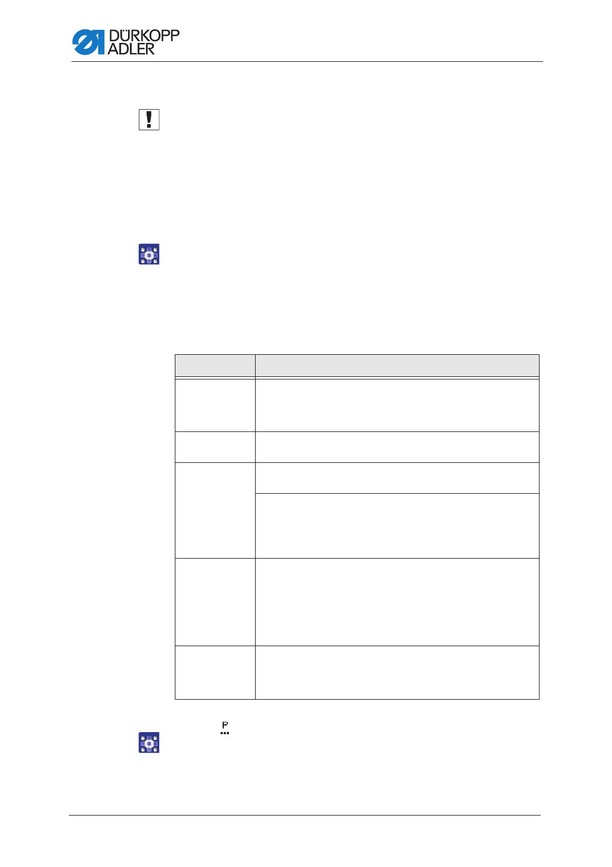
4. Open the Machine Config and select the subitem Bobbin.
5. You can define the following settings:
6. Use on the user level to call up the parameter Bobbin RFW.
7. Using the enlacement check requires that you set the mode to
Monitor.
Menu item Setting options
Bobbin
Monitor
Activation of the sensor units RFW and SSD
0 = PCB 9850 867003
1 = CAN version (right bobbin)
(Value range On/Off, preset: off)
SSD Enlacement check
(Value range On/Off, preset: off)
BRM Bobbin rotation monitor
(Value range On/Off, preset: off)
Length
Delay before the bobbin rotation monitor starts. The machine
calculates the number of stitches automatically depending on the
value entered for the length and the set stitch length.
(Value range 000 - 255, preset: 50)
MsgAfterTrim If detecting an error during the enlacement check or while monitoring
the bobbin rotation, the machine will indicate an error message
during the seam, which must be confirmed with OK. The error
disappears.
If the parameter MsgAfterTrim is active, the error will be displayed
again after the seam has been completed.
(Value range On/Off, preset: off)
StopConfirm If detecting an error during the enlacement check or while monitoring
the bobbin rotation, the machine will indicate an error message and
stop. You must confirm this error before you can resume sewing.
(Value range On/Off, preset: off)
Assembly
Additional Instructions M-TYPE PREMIUM - 04.0 - 07/2019 15
8. If necessary, make additional adjustments in the Monitor menu:
Important
When winding thread onto an empty bobbin for the first time, you must use
winder mode. Otherwise (i.e. during sewing), the machine will detect a
skip stitch and stop sewing.
2.2.2 For M-TYPE PREMIUM machines (with Commander)
Prerequisite:
The software version of the machines must be V04.26 or higher.
1. Log in as a technician by entering the password 25483.
2. Tap the symbol to bring up the navigation pane.
This opens the navigation interface.
Fig. 17: Navigating the burger menu
3. Tap Settings (1).
This opens the Settings interface.
t Clean
Value range 0000 - 5000 [ms]
(Preset: 200)
Duration for which the lens is blown clear with
compressed air. The process takes place after the
thread has been cut.
Motor Stop
Value range On/Off
(Preset: off)
Sewing stops and a notice is shown on the display
when the bobbin is detected to be nearly empty.
If the parameter is not activated, only the LEDs on the
machine arm give a warning if the bobbin is empty.
Foot down
Value range On/Off
(Preset: off)
Sewing foot down if an error occurs during thread
cutting.
(1) - Menu Settings
Assembly
16 Additional Instructions M-TYPE PREMIUM - 04.0 - 07/2019
Fig. 18: Settings
4. Open the Machine Config and tap the subitem Input/Output
Config.
5. Tap the subitem Output Config.
6. Set the outputs X120B.9 and X120B.10 to Mode 2 (cleaning signal
for the RFW).
7. Tap Machine Config on the right-hand side again.
8. Open the Machine Config and tap the subitem RFW/SSD.
9. You can define the following settings:
Icon Menu item Value range
Remaining thread monitor Value range
On/Off
(Preset: off)
Repeat message after FA
If detecting an error during the enlacement
check or while monitoring the bobbin rotation,
the machine will indicate an error message
during the seam, which must be confirmed.
The error disappears.
If the parameter is active, the error will be
displayed again after the seam has been
completed.
Value range
On/Off
(Preset: off)
Confirmation after sewing stop
required
If detecting an error during the enlacement
check or while monitoring the bobbin rotation,
the machine will indicate an error message and
stop. You must confirm this error before you can
resume sewing.
Value range
On/Off
(Preset: off)
Assembly
Additional Instructions M-TYPE PREMIUM - 04.0 - 07/2019 17
10. Call up the parameters using in manual mode on the user level or
using in programming mode.
11. Call up the parameter Bobbin monitor mode in the cross-segment
parameters.
12. Using the enlacement check requires that you set the mode to
Monitor.
13. If necessary, make additional adjustments in the Monitor submenu:
Important
When winding thread onto an empty bobbin for the first time, you must
use winder mode. Otherwise (i.e. during sewing), the machine will detect
a skip stitch and stop sewing.
Enlacement check Value range
On/Off
(Preset: off)
Bobbin rotation monitor Value range
On/Off
(Preset: off)
Length
Seam length before the
bobbin rotation monitor
starts.
Value range
000 - 255 [mm]
(Preset: 50)
Icon Menu item Value range
Sewing stop Sewing stops and a notice is shown on the display
when the bobbin is detected to be nearly empty.
If the parameter is not activated, only the LEDs on the
machine arm give a warning if the bobbin is empty.
Value range On/Off
(Preset: off)
Sewing foot down Sewing foot down if an error occurs during thread cut-
ting.
Value range On/Off
(Preset: off)
t Clean Duration for which the lens is blown clear with
compressed air. The process takes place after the
thread has been cut.
Value range 0000 - 5000 [ms]
(Preset: 200)
Assembly
18 Additional Instructions M-TYPE PREMIUM - 04.0 - 07/2019
2.3 Information messages (M-TYPE PREMIUM)
The machine may display information messages while operating with
the SSD kit. Refer to the table below for the meaning of these messages
as well as potential remedies.
Code Type Notice Possible cause Remedial action
3217 Information RFW right Bobbin is empty. Insert a new bobbin
3223 Information Skip stitch detection A skip stitch has occurred. -
3224 Information Bobbin rotation monitor The bobbin is not rotating. Check the bobbin, advance
the initial thread
3225 Information SSD sensor is soiled. SSD sensor is soiled. Clean the sensor
(using compressed air or a
soft cotton cloth).
  • Page 1 1
  • Page 2 2
  • Page 3 3
  • Page 4 4
  • Page 5 5
  • Page 6 6
  • Page 7 7
  • Page 8 8
  • Page 9 9
  • Page 10 10
  • Page 11 11
  • Page 12 12
  • Page 13 13
  • Page 14 14
  • Page 15 15
  • Page 16 16
  • Page 17 17
  • Page 18 18
  • Page 19 19
  • Page 20 20
  • Page 21 21
  • Page 22 22

Duerkopp Adler 669_PREMIUM User manual

Type
User manual

Ask a question and I''ll find the answer in the document

Finding information in a document is now easier with AI