Page is loading ...

Service Manual
40MHH
High Wall Ductless System
Sizes 09 to 24
TABLE OF CONTENTS
PAGE
SAFETY CONSIDERATIONS 1.........................
INTRODUCTION 1...................................
MODEL/SERIAL NUMBER NOMENCLATURES 2.........
SPECIFICATIONS 3...................................
DIMENSIONS 5.....................................
CLEARANCES 5.....................................
ELECTRICAL DATA 6................................
WIRING 6...........................................
CONNECTION DIAGRAMS 7..........................
WIRING DIAGRAMS 7................................
REFRIGERATION CYCLE DIAGRAMS 9.................
REFRIGERANT LINES 9..............................
ELECTRONIC FUNCTIONS 10.........................
MULTI−FUNCTION BOARD INSTRUCTION 14...........
TROUBLESHOOTING 15..............................
INDOOR UNIT DIAGNOSTIC GUIDE 16.................
DIAGNOSIS AND SOLUTION 17.......................
APPENDIX 34.......................................
DISASSEMBLY INSTRUCTIONS 37.....................
SAFETY CONSIDERATIONS
Installing, starting up, and servicing air−conditioning equipment
can be hazardous due to system pressures, electrical components,
and equipment location (roofs, elevated structures, etc.).
Only trained, qualified installers and service mechanics should
install, start−up, and service this equipment.
Untrained personnel can perform basic maintenance functions such
as cleaning coils. All other operations should be performed by
trained service personnel.
When working on the equipment, observe precautions in the
literature and on tags, stickers, and labels attached to the
equipment.
Follow all safety codes. Wear safety glasses and work gloves. Keep
quenching cloth and fire extinguisher nearby when brazing. Use
care in handling, rigging, and setting bulky equipment.
Read this manual thoroughly and follow all warnings or cautions
included in literature and attached to the unit. Consult local building
codes and National Electrical Code (NEC) for special requirements.
Recognize safety information. This is the safety−alert symbol
!
!
.
When you see this symbol on the unit and in instructions or manuals,
be alert to the potential for personal injury. Understand these signal
words: DANGER, WARNING, and CAUTION.
These words are used with the safety−alert symbol. DANGER
identifies the most serious hazards which will result in severe
personal injury or death. WARNING signifies hazards which
could result in personal injury or death. CAUTION is used to
identify unsafe practices which may result in minor personal injury
or product and property damage. NOTE is used to highlight
suggestions which will result in enhanced installation, reliability, or
operation.
!
WARNING
ELECTRICAL SHOCK HAZARD
Failure to follow this warning could result in personal
injury or death.
Before installing, modifying, or servicing system, main
electrical disconnect switch must be in the OFF
position. There may be more than 1 disconnect switch.
Lock out and tag switch with a suitable warning label.
EXPLOSION HAZARD
Failure to follow this warning could
result in death, serious personal injury,
and/or property damage.
Never use air or gases containing
oxygen for leak testing or operating
refrigerant compressors. Pressurized
mixtures of air or gases containing
oxygen can lead to an explosion.
!
WARNING
CAUTION
!
EQUIPMENT DAMAGE HAZARD
Failure to follow this caution may result in equipment
damage or improper operation.
Do not bury more than 36 in. (914 mm) of refrigerant pipe
in the ground. If any section of pipe is buried, there must be
a 6 in. (152 mm) vertical rise to the valve connections on
the outdoor units. If more than the recommended length is
buried, refrigerant may migrate to the cooler buried section
during extended periods of system shutdown. This causes
refrigerant slugging and could possibly damage the
compressor at start−up.
INTRODUCTION
This Service Manual provides the necessary information to service,
repair, and maintain the indoor units. Section 2 of this manual has an
appendix with data required to perform troubleshooting. Use the Table
of Contents to locate a desired topic.

2
MODEL/SERIAL NUMBER NOMENCLATURES
Table 1—Indoor Units
DESCRIPTION kBTUh V-Ph-Hz ID MODEL No.
High Wall Cooling Only
9
115-1-60
40MHHC09---1
12 40MHHC12---1
9
208/230-1-60
40MHHC09---1
12 40MHHC12---3
18 40MHHC18---3
24 40MHHC24---3
High Wall Heat Pump
9
115-1-60
40MHHQ09---1
12 40MHHQ12---1
9
208/230-1-60
40MHHQ09---1
12 40MHHQ12---3
18 40MHHQ18---3
24 40MHHQ24---3
QH
SYSTEM TYPE
C = COOLING ONLY
Q = HEAT PUMP
INDOOR FAN COIL TYPE
H = HIGH WALL
NOT USED
INDOOR UNIT
40 MH 309
40 = FAN COIL UNIT
MH = MODEL
VOLTAGE
1 =115-1-60
3 = 208/230-1-60
NOMINAL CAPACITY
09 - 3/4 TON
12 - 1 TON
18 - 1-1/2 TONS
24 - 2 TONS
NOT USED
- --
01 17
Week of Manufacture
Year of Manufacture
10001
Sequential Serial Number
V
V = ALL MODELS
Use of the AHRI Certified
TM Mark indicates a
manufacturer’s
participation in the
program For verification
of certification for individual
products, go to
www.ahridirectory.org.

3
SPECIFICATIONS − COOLING ONLY
Table 2—Specifications (Cooling Only)
System
Size 9 12 9 12 18 24
Indoor Model 40MHHC09---1 40MHHC12---1 40MHHC09---3 40MHHC12---3 40MHHC18---3 40MHHC24---3
Electrical
Voltage, Phase,
Cycle
V/Ph/Hz 115-1-60 115-1-60 208/230-1-60 208/230-1-60 208/230-1-60 208/230-1-60
Power Supply Indoor unit powered from outdoor unit
MCA A. 0.3 0.3 0.25 0.25 0.4 0.45
Controls
Wireless Remote Controller
(° F/° C Convertible)
Standard Standard Standard Standard Standard Standard
Wired Remote Controller
(° F/° C Convertible)
Optional Optional Optional Optional Optional Optional
Operating
Range
Cooling Indoor DB
Min -Max
°F(°C) 63~ 90 (17~ 32) 63~ 90 (17~ 32) 63~ 90 (17~ 32) 63~ 90 (17~ 32) 63~ 90 (17~ 32) 63~ 90 (17~ 32)
Piping
Pipe Connection
Size - Liquid
in (mm) 1/4 (6.35) 1/4 (6.35) 1/4 (6.35) 1/4 (6.35) 1/4 (6.35) 3/8 (9.52)
Pipe Connection
Size - Suction
in (mm) 3/8 (9.52) 1/2 (12.7) 3/8 (9.52) 1/2 (12.7) 1/2 (12.7) 5/8 (16)
Indoor Coil
Face Area (sq. ft.) Sq. Ft. 1.14 1.48 1.14 1.48 2.58 2.59
No. Rows 2 2 2 2 2 2
Fins per inch 20 20 20 20 20 20
Circuits 2 2 2 2 2 2
Indoor
Unit Width in (mm) 28.53 (725) 32.00 (813) 28.53 (725) 32.00 (813) 38.36 (974) 43.83 (1113)
Unit Height in (mm) 11.81 (300) 11.81 (300) 11.81 (300) 11.81 (300) 12.8 (325) 13.41 (341)
Unit Depth in (mm) 7.75 (197) 7.75 (197) 7.75 (197) 7.75 (197) 8.87 (225) 9.22 (234)
Net Weight lbs (kg) 16.53 (7.5) 17.64 (8) 16.53 (7.5) 17.64 (8) 23.15 (10.5) 30.86 (14)
Number of Fan Speeds 4 4 4 4 4 4
Airflow (lowest to
highest)
CFM 163/205/239/265 190/239/301/328 177/224/260/286 188/238/305 344/422/506/550 420/514/609/640
Sound Pressure
(lowest to highest)
dB(A) 27/35/39/40 29/36/41/42 28/35/39/40 28/35/40/42 34/39/43/45 39/44/49/49
Air throw Data ft (m) 20 (6.1) 22 (6.7) 20.3 (6.2) 22 (6.7) 24 (7.3) 39.4 (12)
Moisture removal
Pint/h
(L/h)
2.07 (0.98) 3.17 (1.50) 2.07 (0.98) 3.09 (1.46) 4.61 (2.18) 6.38 (3.02)
Field Drain Pipe
Size O.D.
in (mm) 0.625 (16) 0.625 (16) 0.625 (16) 0.625 (16) 0.625 (16) 0.625 (16)
Performance may vary based on the compatible outdoor units. See the respective pages on the outdoor unit's product data for performance data.
COMPATIBILITY TABLE
Indoor Unit 40MHHC09---1 40MHHC12---1 40MHHC09---3 40MHHC12---3 40MHHC18---3 40MHHC24---3
Outdoor Unit Single Zone 38MHRC09A--1 38MHRC12A--1 38MHRC09A--3 38MHRC12A--3 38MHRC18A--3 38MHRC24A--3
Outdoor Unit Multi-Zone
Cooling Only NOT compatible with Multi-zone Outdoor Units.

4
SPECIFICATIONS − HEAT PUMP
Table 3—Specifications (Heat Pump)
System
Size 9 12 9 12 18 24
Indoor Model 40MHHQ09---1 40MHHQ12---1 40MHHQ09---3 40MHHQ12---3 40MHHQ18---3 40MHHQ24---3
Electrical
Voltage, Phase,
Cycle
V/Ph/Hz 115-1-60 115-1-60 208/230-1-60 208/230-1-60 208/230-1-60 208/230-1-60
Power Supply Indoor unit powered from outdoor unit
MCA A. 0.3 0.3 0.25 0.25 0.28 0.45
Controls
Wireless Remote Controller
(° F/° C Convertible)
Standard Standard Standard Standard Standard Standard
Wired Remote Controller
(° F/° C Convertible)
Optional Optional Optional Optional Optional Optional
Operating
Range
Cooling Indoor DB
Min -Max
°F(°C) 63~ 90 (17~ 32) 63~ 90 (17~ 32) 63~ 90 (17~ 32) 63~ 90 (17~ 32) 63~ 90 (17~ 32) 63~ 90 (17~ 32)
Heating Indoor DB
Min -Max
°F(°C) 32~ 86 (0~ 30) 32~ 86 (0~ 30) 32~ 86 (0~ 30) 32~ 86 (0~ 30) 32~ 86 (0~ 30) 32~ 86 (0~ 30)
Piping
Pipe Connection
Size - Liquid
in (mm) 1/4 (6.35) 1/4 (6.35) 1/4 (6.35) 1/4 (6.35) 1/4 (6.35) 3/8 (9.52)
Pipe Connection
Size - Suction
in (mm) 3/8 (9.52) 1/2 (12.7) 3/8 (9.52) 1/2 (12.7) 1/2 (12.7) 5/8 (16)
Indoor Coil
Face Area (sq. ft.) Sq. Ft. 1.14 1.48 1.14 1.48 2.58 2.58
No. Rows 2 2 2 2 2 2
Fins per inch 20 20 20 20 20 20
Circuits 2 2 2 2 2 2
Indoor
Unit Width in (mm) 28.53 (725) 32.00 (813) 28.53 (725) 32.00 (813) 38.36 (974) 43.83 (1113)
Unit Height in (mm) 11.81 (300) 11.81 (300) 11.81 (300) 11.81 (300) 12.8 (325) 13.41 (341)
Unit Depth in (mm) 7.75 (197) 7.75 (197) 7.75 (197) 7.75 (197) 8.87 (225) 9.22 (234)
Net Weight lbs (kg) 21.83(9.9) 22.49(10.2) 21.16 (9.6) 22.49(10.2) 31.97(14.5) 40.12(18.2)
Number of Fan Speeds 4 4 4 4 4 4
Airflow (lowest to
highest)
CFM 153/253/282/312 200/265/306/329 165/229/271/324 212/282/324/353 353/412/529/559 353/483/589/647
Sound Pressure
(lowest to highest)
dB(A) 31/35/39/41 29/38/42/42 31/36/40/42 34/39/41/43 34/39/44/46 38/42/48/49
Air throw Data ft (m) 20.7 (6.3) 22 (6.7) 20.3 (6.2) 22.6 (6.9) 25 (7.6) 37.7 (11.5)
Moisture removal
Pint/h
(L/h)
2.03 (0.96) 3.49 (1.65) 2.05 (0.97) 3.38 (1.6) 4.63 (2.19) 5.73 (2.71)
Field Drain Pipe
Size O.D.
in (mm) 0.625 (16) 0.625 (16) 0.625 (16) 0.625 (16) 0.625 (16) 0.625 (16)

5
DIMENSIONS
Table 4—Dimensions
HIGH WALL UNIT SIZE 9K 12K 9K 12K 18K 24K
Voltage (115V) (115V) (208/230V) (208/230V) (208/230V) (20/230V)
Height In. (mm) 11.81(300) 11.81(300) 11.81(300) 11.81(300) 12.8(325) 13.41(341)
Width In. (mm) 28.53(725) 32.00(813) 28.53(725) 32.00(813) 38.36(974) 43.83(1113)
Depth In. (mm) 7.75(197) 7.75(197) 7.75(197) 7.75(197) 8.87(225) 9.22(234)
Weight-Net
(Cooling Only)
Lbs (kg) 16.53(7.5) 17.64(8) 16.53(7.5) 17.64(8) 23.15(10.5) 30.86(14)
Weight-Net
(Heat Pump)
Lbs (kg) 21.83(9.9) 22.49(10.2) 21.16 (9.6) 22.49(10.2) 31.97(14.5) 40.12(18.2)
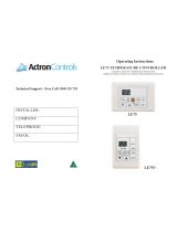
Fig. 1 – Indoor Units
CLEARANCES
6
"
(0.15m
)
min.
5
"
(0.13m)
min.
6'
5
"
(0.13m)
min.
(1.8m)
CEILING
FLOOR
Fig. 2 – Indoor Unit Clearance

6
ELECTRICAL DATA
Table 5—Electrical Data
HIGH WALL UNIT SIZE
INDOOR FAN
MAX FUSE CB AMP
V-Ph-Hz FLA HP
Cooling Only Models
9K
115-1-60
0.425 0.02
Refer to outdoor unit installation instructions –
Indoor unit powered by the outdoor unit
12K 0.425 0.02
9K
208/230-1-60
0.235 0.027
12K 0.235 0.027
18K 0.4 0.037
24K 0.6 0.061
Heat Pump Models
9K
115-1-60
0.425 0.02
12K 0.47 0.027
9K
208/230-1-60
0.25 0.027
12K 0.34 0.027
18K 0.4 0.037
24K 0.45 0.078
LEGEND
FLA - Full Load Amps
WIRING
All wires must be sized per NEC (National Electrical Code) or
CEC (Canadian Electrical Code) and local codes. Use Electrical
Data table MCA (minimum circuit amps) and MOCP (maximum
over current protection) to correctly size the wires and the
disconnect fuse or breakers respectively.
Per the caution note, only stranded copper conductors with a 600
volt insulation rating wire must be used.
Recommended Connection Method for Power and
Communication Wiring:
The main power is supplied to the outdoor unit. The field supplied
14/3 stranded wire with ground with a 600 volt insulation rating,
power/communication wiring from the outdoor unit to indoor unit
consists of four (4) wires and provides the power for the indoor
unit. Two wires are line voltage AC power, one is communication
wiring (S) and the other is a ground wire.
Wiring between indoor and outdoor unit is polarity sensitive.
The use of BX wire is NOT recommended.
If installed in a high Electromagnetic field (EMF) area and
communication issues exists, a 14/2 stranded shielded wire can be
used to replace L2/N and (S) between outdoor unit and indoor unit
landing the shield onto ground in the outdoor unit only.
CAUTION
!
EQUIPMENT DAMAGE HAZARD
Failure to follow this caution may result in equipment
damage or improper operation.
S Wires should be sized based on NEC and local codes.
S Use copper conductors only with a 600 volt insulation
rating wire.
CAUTION
!
EQUIPMENT DAMAGE HAZARD
Failure to follow this caution may result in equipment damage
or improper operation.
SBe sure to comply with local codes while running wire from
the indoor unit to the outdoor unit.
SEvery wire must be connected firmly. Loose wiring may
cause the terminal to overheat or result in unit malfunction.
A fire hazard may also exist. Ensure all wiring is tightly
connected.
SNo wire should be allowed to touch the refrigerant tubing,
compressor or any moving parts.
SDisconnecting means must be provided and shall be located
within sight and readily accessible from the air conditioner.
SConnecting cable with conduit shall be routed through a hole
in the conduit panel.

7
CONNECTION DIAGRAMS
S
L
N
115-1-60
Main
Power Supply
115-1-60
L
N
S
L
N
Power to
Indoor Unit
CONNECTING CABLE
OUTDOOR TO INDOOR
GND
Ground
Indoor
Signal
High
Voltage
115-1-60
115-1-60
FIELD POWER SUPPLY
GND
Indoor
Signal
High
Voltage
Indoor Unit
Power Supply
S
L1 L2
208/230-1-60
Main
Power Supply
L1
L2
S
L1
L2
CONNECTING CABLE
OUTDOOR TO INDOOR
Indoor Unit
Power Supply
208/230-1-60
Indoor
Signal
High
Voltage
GND
Ground
Power to
Indoor Unit
Indoor
Signal
High
Voltage
208/230-1-60
FIELD POWER SUPPLY
GND
208/230-1-60
9K and 12K 115V Indoor Unit 9K and 12K 115V Outdoor Unit 9K to 24K 230V Indoor Unit 9K to 24K 230V Outdoor Unit
Fig. 3 – Connection Diagrams
Notes:
1. Do not use thermostat wire for any connection between indoor and outdoor units.
2. All connections between indoor and outdoor units must be as shown. The connections are sensitive to polarity and will result in a fault code.
WIRING DIAGRAMS
INDOOR WIRING DIAGRAM
ROOM TEMPERATURE
SENSOR
YELLOW
Y/G
RED
N_IN
CN31
RY1
L-OUT
L-IN
BLUE(BLACK)
DISPLAY BOARD
CN18
MULTI-FUNCTION CONTROL BOARD
OPTIONAL
CN3
MAIN BOARD
CN4
CN1
CN40
CN43
CN32
2
CN42
CN41
CN45
CN46
X Y
E 12V/5V
To 7 day programmable
Wire-controller
To Remote
Switch
To Remote
Alarm
4
3
- - - -
element is optional,the actual
shape shall prevail.
This symbol indicates the
INDOOR UNIT
OUTDOOR UNIT
JX1
LN
S
SWING MOTOR1
M
CN19
5(10)
INDOOR FAN
M
5(3or2)
CN12
P_1
3
CN13
Applicable
to AC
motor
only
OPTIONAL
CAP
PIPE TEMPERATURE SENSOR
CN29
CN15
OPTIONAL
CN701
SWITCH
BOARD
2
ROOM TEMPERATURE SENSOR
CN14
Fig. 4 – Wiring Diagram Sizes 09−12 (115V)

8
WIRING DIAGRAMS (CONT)
INDOOR WIRING DIAGRAM
ROOM TEMPERATURE
SENSOR
YELLOW
Y/G
RED
N_IN
CN31
RY1
L-OUT
L-IN
BLUE(BLACK)
DISPLAY BOARD
CN18
MULTI-FUNCTION CONTROL BOARD
OPTIONAL
CN3
MAIN BOARD
CN4
CN1
CN40
CN43
CN32
2
CN42
CN41
CN45
CN46
X Y
E 12V/5V
To 7day programmable
Wire-controller
To Remote
Switch
To Remote
Alarm
4
3
- - - -
element is optional, the actual
shape shall prevail.
This symbol indicates the
INDOOR UNIT
OUTDOOR UNIT
JX1
L1 L2
S
SWING MOTOR1
M
CN19
5(10)
INDOOR FAN
M
5(3or2)
CN12
P_1
3
CN13
Applicable
to AC
motor
only
OPTIONAL
CAP
PIPE TEMPERATURE SENSOR
CN29
CN15
OPTIONAL
CN701
SWITCH
BOARD
2
ROOM TEMPERATURE SENSOR
CN14
Fig. 5 – Wiring Diagram Sizes 09−24 (208−230V)

9
REFRIGERATION CYCLE DIAGRAMS
LIQUID SIDE
GAS SIDE
HEAT
EXCHANGE
(EVAPORATOR)
HEAT
EXCHANGE
(CONDENSER)
COMPRESSOR
2−WAY VALVE
3−WAY VALVE
4−WAY VALVE
COOLING
HEATING
T2 Evaporator
temp. sensor
T1 Room temp.
sensor
ACCUMULATOR
INDOOR OUTDOOR
CHECK VALVE
(Heating Model only)
CAPILIARY TUBE
Fig. 6 – Heat Pumps
REFRIGERANT LINES
IMPORTANT: Both refrigerant lines must be insulated separately.

10
ELECTRONIC FUNCTIONS
Main Protection
Fan Speed is Out of Control
When the indoor fan speed remains too low (300RPM) for a
certain time, the unit stops and the LED displays the failure.
Indoor Fan Delayed Open Function
When the unit starts up, the louver becomes active immediately and
the indoor fan opens 7s later. If the unit runs in the HEATING mode,
the indoor fan will be controlled by the anti−cold wind function.
Zero Crossing Detection Error Protection
If the system detects that the time interval is not correct for a
continuous period of 240s, the unit stops and the LED displays the
failure. The correct zero crossing signal time interval should be
between 6−13ms.
Sensor Protection at Open Circuit and Breaking Disconnection
When there is only one malfunctioning temperature sensor, the air
conditioner keeps working yet displays the error code, in case of
any emergency use. When there is more than one malfunctioning
temperature sensor, the air conditioner stops working.
Operation Modes and Functions
FAN Mode
1 Outdoor fan and compressor stop
2 Temperature setting function is disabled, and no setting
temperature is displayed.
3 Indoor fan can be set to high/med/low/auto
4 The louver operates the same in the COOLING mode.
5 Auto fan
Fig. 7 – Auto Fan
COOLING Mode
Indoor Fan Running Rules
In the COOLING mode, the indoor fan runs all the time and the
speed can be selected as high, medium, low and auto. When the
setting temperature is reached, if the compressor stops running, the
indoor fan motor runs at the minimum or setting speed.
The indoor fan is controlled by the rules shown in Fig. 8.
Setting fan
speed
Actual fan speed
++ +*
$+˄ +˅
%
&
00 0=
'00 0
(
)
// /'
*// /
+
,
T1-Td ć(°F)
L
// /'
H
+˄+ +*
M
00 0=
Fig. 8 – Indoor Fan Running Rules
The AUTO fan is controlled by the rules shown in Fig. 9.
Fig. 9 – Indoor Fan Running Rules
Evaporator Temperature Protection
When the evaporator temperature is less than the setting value, the
compressor stops.
HEATING Mode
Indoor Fan Running Rules
When the compressor is on, the indoor fan can be set to
high/med/low/auto/mute. When the indoor unit coil temperature is
low, the anti−cold air function starts and the indoor fan motor runs
at a low speed and the speed can not be changed. When the
temperature is lower than the setting value, the indoor fan motor
stops.
When the indoor temp reaches the setting temperature, the
compressor stops, the indoor fan motor runs at the minimum speed
or setting speed. (The anti−cold air function is valid). The indoor
fan is controlled as shown in Fig. 10.
Setting fan
speed
Actual fan speed
H˄=H˅
H+(H+=H+G)
M(M=M)
M+(M+=M+Z)
L(L=L)
L+(L+=L+D)
H-˄H-=H-G)
M-(M-=M-Z)
L-(L-=L-D)
T1-Tdć
L
H
M
Fig. 10 – Indoor Fan Running Rules
Auto Fan Action in HEATING Mode
a
b
c
d
T1
e
Fig. 11 – Auto Fan Action in HEATING Mode

11
DEFROST Mode
The air conditioner enters the DEFROST mode according to the
T3 temperature value and the T3 temperature change value range
plus the compressor running time.
During the DEFROST mode, the compressor continues to runs,
the indoor and outdoor motors stop, and the indoor unit defrost
lamp illuminates and
appears.
If any one of the following items is satisfied, the defrosting finishes
and the machine reverts to the normal heating mode.
−−−−T3 rises to be higher than TCDE1
_C.
−−−−T3 keeps to be higher than TCDE2
_C for 80 seconds.
−−−−The machine has run for 15 minutes in defrosting mode.
Evaporator Coil Temperature Protection
TEstop
T2
Resume
Off
Decrease
TEdown
TEH2
Hold
Fig. 12 – Evaporator Coil Temperature Protection
NOTE: The following applies to Fig. 12:
S Off: Compressor stops
S Decrease: Decrease the running frequency to the lower
level
S Hold: Keep the current frequency
S Resume: No limitation for frequency
When the evaporator temperature is higher than the setting
protection value, the compressor stops.
Auto−Mode
This mode can be chosen with the remote controller and the setting
temperature can be changed between 62.6
_F(17_C)~86_F(30_C).
In the AUTO mode, the machine chooses the COOLING,
HEATING or FAN−ONLY mode according to ΔT (ΔT =T1−Ts).
Table 6—Auto Mode
ΔT=T1-Ts Running mode
ΔT>2℃ Cooling
-2≤ΔT≤2℃ Fan-only
ΔT<-2℃ Heating
The indoor fan runs under auto fan in the relevant mode. The
louver operates same as in relevant mode. If the machine switches
mode between HEATING and COOLING, the compressor stops
for 15 minutes and then chooses the mode according to T1−Ts. If
the setting temperature is modified, the machine chooses the
running function again.
DRY Mode
Indoor Fan Speed is Fixed
Indoor fan speed is fixed at breeze and can not be changed. The
louver angle is the same as in the COOLING mode.
Low Indoor Room Temperature Protection
In the DRY mode, if the room temperature is lower than 50
_F
(10
_C), the compressor stops and will not resume until the room
temperature exceeds 53.6
_F (12_C).
Evaporator Anti−Freezing Protection
The evaporator anti−freezing protection condenser high
temperature protection and outdoor unit frequency limit are active
and the same as that in the COOLING mode.
Outdoor Fan
The outdoor fan operates the same as in the COOLING mode.
FORCED OPERATION Function
When the unit is off, press TOUCH to engage the FORCED
AUTO mode. Press TOUCH again within 5 seconds to engage
the FORCED COOLING mode. In the FORCED AUTO,
FORCED COOLING or any other operation mode, press
TOUCH to off the unit.
S FORCED OPERATION mode: In the FORCED
OPERATION mode, all the general protections and
remote control are available.
Operation Rules
S FORCED COOLING mode: The compressor runs at
the F2 frequency and the indoor fan runs in the
BREEZE mode. After running for 30 minutes. the
machine enters AUTO mode at the 75.2
_F(24_C)
setting temperature.
S FORCED AUTO mode: The FORCED AUTO mode
is the same as the normal AUTO mode with a
75.2
_F(24_C) setting temperature.
Timer Function
Timing range is 24 hours.
Timer on. The machine turns on automatically when reaching the
setting time.
Timer off. The machine turns off automatically when reaching the
setting time.
Timer on/off. The machine turns on automatically when reaching
the setting “on” time, and then turns off automatically when
reaching the setting “off” time.
Timer off/on. The machine turns off automatically when reaching
the setting “off” time, and then turns on automatically when
reaching the setting “on” time.
The timer function will not change the system’s current operation
mode. Suppose the system is off now, it will not start up firstly
after setting the “timer off” function. And when reaching the
setting time, the timer LED will be off and the system’s running
mode has not been changed. The setting time is relative time.
The system will exit the timer function when it has malfunction.

12
Sleep Function
The sleep function is available in cooling, heating or auto mode.
Operation process in SLEEP mode is as follows:
S When cooling, the setting temperature rises 33.8_F(1_C)
(be lower than 86
_F(30℃) every one hour, 2 hours later
the setting temperature stops rising and the indoo)r fan is
fixed at low speed.
When heating, the setting temperature decreases 33.8
_F(1_C) (be
higher than 62.6
_F(17℃) every one hour, 2 hours later the setting
temperature stops rising and indoor fan is fixed at low speed.
(Anti−cold wind function has the priority).
Operation time in SLEEP mode is 7 hours. After 7 hours the
system exits this mode and turns off.
AUTO−RESTART Function
The indoor unit is equipped with the AUTO−RESTART
function, which is carried out through an auto−restart module. In
the event of a sudden power failure, the module memorizes the
setting conditions prior to the power failure. The unit resumes the
previous operation setting (not including the SWING function)
automatically three (3) minutes after the power returns.
If the memorization condition is the FORCED COOLING mode,
the unit will run in the COOLING mode for 30 minutes and turn
to the AUTO mode at the 75.2
_F(24_C) setting temperature.
If the air conditioner is off before the power turns off and the air
conditioner is required to start up, the compressor delays start up
for 1 minute before powering on. In other instances, the
compressor waits three (3) minutes before restarts.
Refrigerant Leak Detection
With this new technology, the display area displays “EC” when the
outdoor unit detects a refrigerant leak. This function is only active
in cooling mode. It can better prevent the compressor being
damaged by refrigerant leakage or compressor overload.
S Open Condition: When the compressor is active, the
value of the Coil temperature of evaporator T2 has no
change or very little change.
Louver Position Memory Function
When starting the unit again after shutting down, the louver returns
to the angle originally set by the user, however the precondition is
that the angle must be within the allowable range, if it exceeds, it
will memorize the maximum angle of the louver. During operation,
if the power fails or the end user shuts down the unit in the turbo
mode, the louver returns to the default angle.
46_F (8_C) Heating
When the compressor is running, the indoor fan motor runs
without the ANTI−COLD air function. When the compressor is
off, the indoor fan motor is off.
Silence Operation
Press the SILENCE button on the remote controller to initiate the
SILENCE function. When the SILENCE function is activated,
the compressor running frequency remains lower than F2 and the
indoor unit emits a faint breeze, which reduces the noise to the
lowest level and create a quiet and comfortable room for the user.
Self clean
For heat pump models which are provided with this function, after
running in the COOLING or DRYING mode, if the user presses
“Self Clean” on the remote controller, the indoor unit runs in the
FAN ONLY mode momentarily, then the low heat operation and
finally runs in FAN ONLY again. This function can keep the inside
of the indoor unit dry and prevent mold from breeding within the
unit.
FOLLOW ME
If the indoor PCB receives the signal which results from pressing
FOLLOW ME on the remote controller, the buzzer emits a
sound which indicates the FOLLOW ME function is initiated.
However, when the indoor PCB receives a signal from the remote
controller every 3 minutes, the buzzer will not respond.
When the unit is running with the FOLLOW ME function, the
PCB controls the unit according to the temperature from the
FOLLOW ME signal, and the temperature collection function of
the room temperature sensor is shielded, however the error
detective function of room temperature sensor remains valid.
When the FOLLOW ME function is available, the PCB controls
the unit according to the room temperature from the remote
controller and the setting temperature.
The PCB will take action to the mode change information from
remote controller signal, however it will not be affected by the
setting temperature.
When the unit is in the FOLLOW ME mode, if the PCB does
not receive a signal from the remote controller for 7 minutes or
pressing the FOLLOW ME button again, the FOLLOW ME
function turns off automatically, and the temperature controls the
unit according to the room temperature detected from its own
room temperature sensor and setting temperature.

13
Point Check Function
Press the remote controller’s LED DISPLAY or LED or MUTE button three times, and then press the AIR DIRECTION or SWING
button three times in ten seconds, the buzzer rings for two seconds. The air conditioner enters into the information enquiry status.
Press the LED DISPLAY or AIR DIRECTION button to check the next or front item’s information.
When the air conditioner enters the information enquiry status, it displays the code name in 2 seconds (see Table 7).
Table 7—Information Enquiry
ENQUIRY INFORMATION DISPLAYING CODE MEANING
T1 T1 T1 temp.
T2 T2 T2 temp.
T3 T3 T3 temp.
T4 T4 T4 temp.
T2B Tb T2B temp.
TP TP TP temp.
TH TH TH temp.
Targeted Frequency FT Targeted Frequency
Actual Frequency Fr Actual Frequency
Indoor Fan Speed IF Indoor fan speed
Outdoor Fan Speed OF Outdoor fan speed
EXV Opening Angle LA EXV opening angle
Compressor continuous running time CT Compressor continuous running time
Compressor stop causes ST Compressor stop causes
Reserve A0
Reserve A1
Reserve b0
Reserve b1
Reserve b2
Reserve b3
Reserve b4
Reserve b5
Reserve b6
Reserve dL
Reserve Ac
Reserve Uo
Reserve Td
When the system enters the information enquiry status, it displays the code value for 25 seconds (see Table 8).
Table 8—Information Enquiry
ENQUIRY
INFORMATION
DISPLAY VALUE MEANING REMARK
T1,T2,T3,T4,
T2B,TP,TH,
Targeted
Frequency,
Actual
Frequency
-1F,-1E,-1d,-1c,-1b,-1A -25,-24,-23,-22,-21,-20
1. The displaying temperature is the actual value.
2. The temperature is _C no matter what kind of remote
controller is used.
3. T1,T2,T3,T4,T2B display range:-25~70, TP display
range:-20~130.
4. Frequency display range: 0~159HZ.
5. If the actual value exceeds the range, it displays the
maximum value or minimum value.
-19—99 -19—99
A0,A1,…A9 100,101,…109
b0,b1,…b9 110,111,…119
c0,c1,…c9 120,121,…129
d0,d1,…d9 130,131,…139
E0,E1,…E9 140,141,…149
F0,F1,…F9 150,151,…159
Indoor fan
speed
/Outdoor fan
speed
0 OFF
1,2,3,4
Low speed, Medium speed, High
speed, Turbo
For some big capacity motors.
14-FF
Actual fan speed = Display value
turns to decimal value and then
multiply 10. The unit is RPM.
For some small capacity motors, the display value is from 14-FF
(hexadecimal), the corresponding fan speed range
is from 200-2550 RPM.
EXV opening
angle
0-FF
Actual EXV opening value =
Display value turns to decimal
value and then multiply 2.
Compressor
continuous
running time
0-FF 0-255 minutes
If the actual value exceeds the range, it displays the
maximum value or minimum value.
Compressor
stop causes
0-99
For the detailed meaning, please
consult with engineer
Decimal display
Reserve 0-FF

14
MULTI−FUNCTION BOARD INSTRUCTION
Function
The multi−function board receives the 4−cored wired controller signal and the CP remote on−off signal (ON−OFF command signal). The
board then converts the signal to a communication signal and sends the signal to the main control board. The multi−function board can
output the alarm signal.
CP Remote ON−OFF
For the CP command, closed indicates the remote on−off control signal OFF. Disconnected indicates the remote on−off control signal ON.
The control requires 3 seconds to determine the on/off status. The CP command is delivered one time (immediately) after power on.
The Dip−switch F2 setting status is shown in Table 9.
Table 9—Dip−switch F2 setting status
Dip-switch 2 Dip-switch 1 Remote on-off control status
OFF OFF Disconnected send CP, closed cancel CP
ON OFF Closed send CP, disconnected cancel CP
ON−OFF Control
The control requires 3 seconds to determine the on/off status. The ON−OFF command is not delivered after power on, only when the status
changes. The control can then send the command. When the ON−OFF control disconnects, it sends the switch−on signal. The unit runs in
AUTO mode, AUTO FAN speed (75.2_F (24_C)) setting temperature. When the ON−OFF control is closed, it sends a switch−off signal. The
Dip−switch F2 setting status is shown in Table 10.
Table 10—Dip−switch F2 setting status
Dip-switch 2 Dip-switch 1 Remote on-off control status
OFF ON Disconnected send ON, closed send OFF
ON ON Closed send OFF,disconnected send ON
Alarm Port Output
When the system is OFF, the output signal is closed.
When the system is in a malfunction state, the output signal is closed.
When the system is ON, the output signal is disconnected.
Wiring Diagram
Connected to 4−cored wired controller
Fig. 13 – Wiring Diagram
NOTE: Use shield cables to connect the 4−cored wired controller. The length should not exceed 164 ft. (50m).

15
TROUBLESHOOTING
Safety
Electricity power is kept in capacitors even if the power supply is shut off.
NOTE: Remember to discharge the electricity power in capacitor.
Electrolytic Capacitors
(HIGH VOLTAGE! CAUTION!)
Fig. 14 – Electrolytic Capacitors
For other models, please connect discharge resistance (approximately 100
Ω 40W) or a soldering iron (plug) between the +, − terminals of the
electrolytic capacitor on the contrary side of the outdoor PCB.
Fig. 15 – Discharge Position
NOTE: Fig. 15 is for reference only. The plug on your unit may differ.

16
INDOOR UNIT DIAGNOSTIC GUIDE
Table 11—Indoor Unit Error Display
OPERATION LAMP TIMER LAMP DISPLAY LED STATUS
H 1 time
X E0 Indoor unit EEPROM parameter error
H 2 times
X E1 Indoor / outdoor units communication error
H 3 times
X E2 Zero-crossing signal detection error
H 4 times
X E3 Indoor fan speed has been out of control
H 5 times
X E4 Indoor room temperature sensor T1 open circuit or short circuit
H 6 times
X E5 Evaporator coil temperature sensor T2 open circuit or short circuit
H 7 times
X EC Refrigerant leakage detection
H 1 time
O F0 Overload current protection
H 2 times
O F1 Outdoor ambient temperature sensor T4 open circuit or short circuit
H 3 times
O F2 Condenser coil temperature sensor T3 open circuit or short circuit
H 4 times
O F3 Compressor discharge temperature sensor T5 open circuit or short circuit
H 5 times
O F4 Outdoor unit EEPROM parameter error
H 6 times
O F5 Outdoor fan speed has been out of control
H 1 time H
P0 IPM malfunction or IGBT over-strong current protection
H 2 times H
P1 Over voltage or over low voltage protection
H 3 times H
P2 High temperature protection of IPM module or compressor top
H 4 times H
P3* Outdoor ambient temperature too low.
H 5 times H
P4 Inverter compressor drive error
H 6 times H
P5 Indoor units mode conflict (multi-zone ONLY)
O(light) X(off) H(flash)
NOTE: P3
1 In the HEATING mode, when the outdoor temperature is lower than −13
_F(−25_C) for 1 hour, the indoor unit display error code P3.
2 If the outdoor temperature is higher than −7.6
_F(−22_C) for 10 minutes and compressor stop for 1 hour or outdoor temperature is
higher than 23
_F(−5_C) for 10 minutes, then the unit will return to work.
* Fault Symptom: The display board shows a garbled code or a code that is not an error code found in the service manual nor a
temperature reading.
Table 12—Indoor Unit Error Display
No. Problems
LED3
(Green)
LED2
(Red)
IU display
1 standby for normal O X
2 Operation normally X O
3 IPM malfunction or IGBT over-strong current protection
H
X P0
4 Over voltage or too low voltage protection O O P1
5 EEPROM parameter error O
H
E5
6 Inverter compressor drive error X
H
P4
7 Inverter compressor drive error
H
O P4
8 Inverter compressor drive error
H H
P4
O(light) X(off) H(2.5Hz flash)

17
DIAGNOSIS AND SOLUTION
EEPROM Parameter Error Diagnosis and Solution (E0/F4)
Error Code E0/F4
Malfunction decision conditions Indoor or outdoor PCB main chip does not receive feedback from the EEPROM chip.
Supposed causes
·Installation mistake
·PCB faulty
Troubleshooting
Yes
Replace the indoor/outdoor
main PCB.
Power off, then restart the
unit 2 minutes later.
EEPROM: A read−only memory whose contents can be erased and reprogrammed using a pulsed voltage. For the EEPROM chip location,
please refer to Fig 16 and Fig. 17.
Fig. 16 – Indoor PCB
Fig. 17 – Outdoor PCB (18K Model)
NOTE: The two photos above are for reference only and they may differ from the actual unit.

18
DIAGNOSIS AND SOLUTION (CONT)
Indoor / outdoor unit’s communication diagnosis and solution (E1)
Error Code E1
Malfunction Decision Conditions
Indoor unit does not receive the feedback from outdoor unit during 110 seconds and this condition
happens four times continuously.
Supposed Causes
S Wiring mistake
S Indoor or outdoor PCB faulty
Troubleshooting
Measure Vs., is it a positive fluctuation?
(Vs represents the voltage S and N of the
outdoor unit. Red pan-S, Black pan-N)
Power off, then restart the unit 2 minutes later
Replace the indoor main PCB.
Power on. Is the error resolved?
No
Check the indoor wiring connection
Yes
Check whether the
reactor is normal
Yes
No
Check the outdoor wiring connection
Replace the reactor
Yes
Replace the outdoor main PCB.
Power on. Is the error resolved?
Replace the indoor main PCB
No
Replace the outdoor main PCB.
Yes
No
Yes
Yes

19
DIAGNOSIS AND SOLUTION (CONT)
Fig. 18 – Test the DC Voltage
Use a multimeter to test the DC voltage between L2 port and S port of the outdoor unit. The red pin of the multimeter connects with the L2
port while the black pin is for the S port. When air conditioner is running normal, the voltage moves alternately between −50V to 50V. If the
outdoor unit has a malfunction, the voltage will move alternately with positive value. If the indoor unit has malfunction, the voltage will have
a certain value.
Fig. 19 – Test the Reactor Resistance
Use a multimeter to test the resistance of the reactor which does not connect with the capacitor. The normal value should be around zero (0)
ohm. Otherwise, the reactor has a malfunction and needs to be replaced.

20
DIAGNOSIS AND SOLUTION (CONT)
Zero crossing detection error diagnosis and solution (E2)
Error Code E2
Malfunction decision conditions
When the PCB does not receive a zero crossing signal feedback for 4 minutes or the zero crossing
signal time interval is abnormal.
Supposed causes
S Connection mistake
S PCB faulty
Troubleshooting
Check if the connections and
power supply are normal.
Correct the connections. Turn on the
unit when the power supply is good.
No
Yes
Indoor main PCB is
defective. Replace indoor
main PCB.
/