Page is loading ...

45-05192
UTILITY 17 POLY CART
FORM NO. 45614 (09/05/18)
the fastest way to purchase parts
www.speedepart.com
youtube.com/c/agrifab
Video
Instruction
Guide
Want more information or assembly tips?

2
CAUTION: vehicle braking and stability may
be affected with the addition of an acces-
sory or an attachment. Be aware of chang-
ing conditions on slopes.
Training
• Exercise caution at all times when using power
equipment.
• Read this owners manual before attempting to
assemble or operate the cart.
• Read the vehicle owners manual and know how to
operate your tractor, before using the cart attachment.
• Do not at any time carry passengers in this cart. It
has not been designed to carry passengers.
• Never allow children to operate the tractor or the cart
attachment.
• Do not allow adults to operate the tractor or cart
attachment without proper instructions.
Remember, any power equipment can cause injury if operated improperly or if the user does not understand how to
operate the equipment. Exercise caution at all times when using power equipment.
Look for this symbol to point out important
safety precautions. It means — ATTENTION!
Become alert! Your safety is involved
SAFETY
Operation
• Always begin with the transmission in rst (low) and
gradually increase speed as conditions permit.
• Tow the cart at reduced speed over rough terrain and
hillsides or near creeks and ditches to prevent tipping
over and loss of control. Do not drive too close to a
creek or ditch.
• Vehicle braking and stability may be affected with the
attachment of this cart. Do not ll cart to maximum
weight capacity without checking the capability of the
towing vehicle to safely pull and stop with the cart
attached.
• Before operating vehicle on any grade (hill) refer
to the safety rules in the vehicle owner's manual
concerning safe operation on slopes. Refer also to
the slope guide on page 9 of this manual. Stay off
steep slopes!
• Do not tow this cart on highways or on public
thoroughfares.
• Maximum towing speed is 7 m.p.h.
Maintenance
• Follow maintenance and lubrication instructions as
outlined in this manual.

3
A
(1)
B
(1)
C
(4)
D
(8)
E
(4)
F
(9)
H
(1)
J
(2)
L
(1)
K
(1)
N
(1)
I
(4)
G
(2)
M
(1)
SHOWN FULL SIZE
NOT SHOWN FULL SIZE
O
(2)
47407
43001
43661
43840
47189
47810
46980
43528
46855
46289
47408
23353
43343
47622
HA21362
FULL SIZE HARDWARE CHART
REF PART NO. QTY. DESCRIPTION
A 47407 1 Hex Bolt, 5/16" x 4"
B 43001 1 Hex Bolt, 3/8" x 1"
C 43661 4 Hex Bolt, 1/4" x 1"
D 43840 8 Hex Bolt, 5/16" x 1-1/4"
E 47189 4 Nylock Nut, 1/4"
F 47810 9 Nylock Nut, 5/16"
G 46980 2 SEMS Nut, 5/16"
H HA21362 1 Nylock Nut, 3/8"
REF PART NO. QTY. DESCRIPTION
I 43528 4 Flat Washer, 1"
J 46855 2 Cotter Pin, 3/16" x 2"
K 43343 1 Hair Cotter Pin, 3/32"
L 47622 1 Spring Puller Tool
M 47408 1 Extension Spring
N 23353 1 Hitch Pin
O 46289 2 Spacer

4
TOOLS REQUIRED FOR ASSEMBLY
(1) Pliers
(2) 7/16" Wrenches
(2) 1/2" Wrench
(2) 9/16" Wrenches
FIGURE 1
7
G
5
A
F
1. Poly Tray
2. Wheel Support
3. Latch Stand Plate
7. Foot Pedal Latch
8. Hitch Bracket
9. Axle
4. Latch Stand Bracket
5. Draw Bar Tongue
6. Wheels (2)
1
2
3
5
7
4
8
9
6
41862
24750
45611
28258
27379
23014
24386
24497
25106
CARTON CONTENTS
ASSEMBLY
STEP 1: (SEE FIGURE 1)
• Verify that all parts and all fasteners on pages 3 and
4 are included in the carton and parts bag. Refer
to page 3 to identify fasteners used in the following
instructions.
• Place the foot pedal latch (7) through the slot in the
tongue (5). Assemble the hex bolt (A) through the
tongue, the lever, and two (SEMS) hex nuts (G)
placed on each side of the lever. Assemble the nylock
nut (F) onto the end of the hex bolt (A) and tighten
so that the hex bolt (A) can still rotate freely. Tighten
the two (SEMS) hex nuts (G) against each side of the
foot pedal latch (7) so that it is centered in the slot.

5
FIGURE 2
FIGURE 3
STEP 2: (SEE FIGURE 2)
• Hook the short end of the spring (M) into the hole in
the foot pedal latch. Use the spring puller tool (L) to
hook the long end of the spring into the square hole
in the tongue. The spring puller tool can be stored
when nished.
STEP 3: (SEE FIGURE 3)
• Assemble the end of the hitch bracket (8) down
through the slot at the front of the tongue. Fasten it
to the tongue using the hex bolt (B) and hex nut (H).
Tighten.
• Assemble the hitch pin (N) and hair cotter pin (K) to
the tongue and hitch bracket.
FIGURE 4
9
2
STEP 4: (SEE FIGURE 4)
• Lay the tongue (open side facing up) onto the wheel
support (2). Assemble the axle (9) through the wheel
support and the tongue.
STEP 5: (SEE FIGURE 5)
• Assemble a spacer (O), a washer (I), a wheel (6)
with the valve stem facing out, and another washer
(I), onto the axle. Secure by inserting a cotter pin (J)
through the hole in the axle and spreading the ends.
Repeat for other wheel.
FIGURE 5
6
I
I
J
O
B
N
8
K
H
M
L

6
FIGURE 7
FIGURE 6
C
E
4
3
D
F
STEP 6: (SEE FIGURE 6)
• Assemble the latch stand plate (3) and the latch
stand bracket (4) at the front of the tray using four hex
bolts (C), and hex nuts (E). The aligning tab on the
bottom of the latch stand bracket must be towards the
rear of the cart. Tighten.
STEP 7: (SEE FIGURE 7)
• Place the tray onto the wheel support and position
it so that the latch stand bracket locks into the foot
pedal latch. Fasten the tray to the wheel support
using eight hex bolts (D) and hex nuts (F). Tighten.
HINT: Using tape to hold the hex bolts in place may ease
assembly.

7
NOTES

8
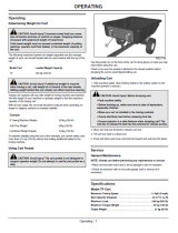
CAUTION: vehicle braking and stability
may be affected with the addition of an
accessory or an attachment. Be aware of
changing conditions on slopes.
1. At the beginning of each season, using a light
machine oil, lubricate the latch, the latch pivot bolt,
and the area of the axle where the draw bar tongue
pivots.
2. Check periodically for loose bolts.
3. Keep tires lled to the recommended tire pressure
printed on the tire.
1. Refer to the vehicle owners manual for instructions on
safe operation on slopes.
2. Use the slope guide provided on page 9 of this
manual to determine whether slope angle is too steep
for safe operation.
3. For best handling and traction, distribute the weight of
the load evenly in the cart.
4. Always test to make sure your tractor has adequate
towing and braking capabilities whenever hauling a
substantial amount of weight in your cart. Use extra
caution when operating on slopes.
5. To dump material from the cart, release the spring
latch on the tongue by stepping on the foot pedal
latch. The cart bed will then tilt backwards to empty
its contents. After emptying, pull the front of the bed
down toward the cart tongue until the latch snaps into
place.
6. The maximum towing speed for this cart is 7 m.p.h.
NOTE
DO NOT EXCEED WEIGHT CAPACITY OF CART
(See the specications on this page.)
One cubic foot of dirt weighs approximately 80 lbs.
Tires: 16" x 6.5-8" Pneumatic
Axle: 1" Dia. Steel
Capacity: Up to 800 Lbs. Max.
Approx. Sh. Wt.
106 Lbs.
CART SPECIFICATIONS
CAUTION: to avoid possible injury,
before releasing the latch be sure that
no one is near the cart.
OPERATION MAINTENANCE
WARNING: Over-inated tires can explode,
causing serious injury. To avoid injury,
NEVER inate tires beyond the maximum
pressure printed on the sidewall of the tire.
ALWAYS use a hand pump to safely inate
tires.

9
SLOPE GUIDE
(Keep this sheet in a safe place for future reference.)
Use this guide to determine if a slope is safe for the operation of your tractor and cart. Refer
also to the instructions in your vehicle owners manual.
CAUTION: DO NOT OPERATE YOUR TRACTOR AND CART ON A
SLOPE IN EXCESS OF 10 DEGREES. BE SURE OF YOUR TRAC-
TOR'S TOWING AND BRAKING CAPABILITIES BEFORE OPERATING
ON A SLOPE. AVOID ANY SUDDEN TURNS OR MANEUVERS WHILE
ON A SLOPE.
A POWER POLE
A CORNER OF A BUILDING
OR A FENCE POST
FOLD ALONG DOTTED LINE, REPRESENTING A 10 DEGREE SLOPE
SIGHT AND HOLD THIS LEVEL WITH A VERTICAL TREE

10
REPAIR PARTS ILLUSTRATION
MODEL NUMBER 45-05192
1
20
3
4
19
2
9
15
13
6
13
15
14
5
16
7
24
11
16
21
12
17
22
8
23
10
18
25

11
REF. PART NO. QTY. DESCRIPTION
1 41862 1 Poly Tray
2 25106 1 Wheel Support
3 24386 1 Latch Stand Plate
4 24497 1 Latch Stand Bracket
5 24750 1 Tongue, Draw Bar
6 45611 2 Wheel Assembly
7 28258 1 Foot Pedal Latch
8 23014 1 Hitch Bracket
9 27379 1 Axle, 1"
10 HA21362 1 Hex Nut, 3/8-16 Nylock *
11 47407 1 Hex Bolt, 5/16" x 4"
12 47622 1 Spring Puller Tool
13
45611BRG
4 Wheel Bearing, 1"
14 46855 2 Cotter Pin, 3/16" x 2"
15 43528 4 Washer, 1"
16 47810 9 Hex Nut, 5/16-18 Nylock *
17 43001 1 Hex Bolt, 3/8-16 x 1" *
18 43840 8 Hex Bolt, 5/16-18 x 1-1/4"
19 47189 4 Hex Nut, Nylock 1/4-20
20 43661 4 Hex Bolt, 1/4-20 x 1" *
21 47408 1 Extension Spring
22 23353 1 Hitch Pin
23 43343 1 Hair Cotter Pin, 3/32" *
24 46980 2 Hex Nut, 5/16-18 (SEMS)
25 46289 2 Spacer
45614 1 Owner's Manual
REPAIR PARTS LIST
MODEL NUMBER 45-05192

REPAIR PARTS
Agri-Fab, Inc.
809 South Hamilton
Sullivan, IL. 61951
217-728-8388
www.agri-fab.com
the fastest way to purchase parts
www.speedepart.com
/