Page is loading ...

Installation Instructions
for your new undercounter
TRASH MASHER* COMPACTOR
BEFORE YOU USE YOUR COMPACTOR
Be sure your compactor is properly installed in an appropriate level area
and a place suitable for the size, function and
protection of the compactor.
ELECTRICALREQUIREMENTS
Observe All Governing Codes and Ordinances
A 120-Volt, 60-Hz, AC only, 1 !%Ampere, fused electrical supply is required. (Time delay fuse or circuit breaker is
recommended.) It is recommended that a separate circuit serving only this appliance be provided.
DO NOT use
an extension cord.
RECOMMENDED GROUNDING METHOD
DO NOT, UNDER ANY CIRCUMSTANCES,
REMOVE THE POWER SUPPLY CORD
GROUNDING PRONG.
3-PRONG
GROUNDING TYPE
WALL RECEPTACLE
For your personal safety, this appliance must be grounded.
This appliance is equipped with a power supply cord having a
3-prong grounding plug. To minimize possible shock hazard,
the cord must be plugged into a mating 3-prong grounding type
wall receptacle, grounded in accordance with local codes and
ordinances. If a mating wall receptacle is not available, it is the
personal responsibility and obligation of the customer to have
a properly grounded. 3-prong wall receptacle installed by a
qualified electrician. See figure 7.
FIGURE I
* Trademarks in Canada Used by Authority of Canadian Trademark Owner, WHIRLPOOL CORPORATION, U.S.A.
- IMPORTANT -
00 NOT REUOVE THIS INSTRUCTION SHEET UNTIL READY FOR INSTALLATION.
AlTEll COMPLETING THE /AfSTALl.ATIO/V, SAVE THESE lMSTRUCTKJMS FOH FUTURE USE.
1
Part No. 4152821
INSTALLATION INSTRUCTIONS
1.
2.
3.
4.
5.
BEFORE YOU BEGIN, READ THE FOLLOWING INSTRUCTIONS COMPLETELY AND
CAREFULLY. THEY WILL SIMPLIFY THE INSTALLATION.
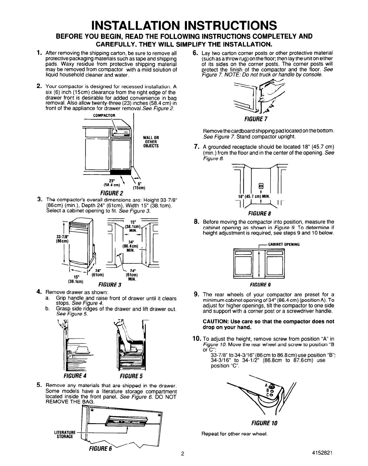
After removing the shipping carton, be sure to remove all
6.
Lay two carton corner posts or other protective material
protective packaging materials such as tape and shipping (such as a throw rug) on the floor; then lay the unit on either
pads. Waxy residue from protective shipping material of its sides on the corner posts. The corner posts will
may be removed from compactor with a mild solution of
protect the finish of the compactor and the floor. See
liquid household cleaner and water.
Figure 7. NOTE: Do not truck or handle by console.
Your compactor is designed for recessed installation. A
six (6) inch (15cm) clearance from the right edge of the
drawer front is desirable for added convenience in bag
removal. Also allow twenty-three (23) inches (58.4 cm) in
front of the appliance for drawer removalSee Figure 2.
COMPACTOR
I
WALL OR
OTHER
OBJECTS
(5fJYcmj ’ ’ 6”
(15cml
FIGURE 2 ’
The compactor’s overall dimensions are: Height 33-7/8”
(86cm) (min.), Depth 24” (slcm), Width 15” (38.lcm).
Select a cabinet opening to fit. See Figure 3.
T-
33-l/8”
(Mcm)
I
5
-1. f
Remove drawer as shown:
a. Grip handle and raise front of drawer until it clears
stops. See Figure 4.
b. Grasp side ridges of the drawer and lift drawer out.
See Figure 5.
FIGURE 4
FIGURE 5
Remove any materials that are shipped in the drawer.
Some models have a literature storage compartment
located inside the front panel. See Figure 6. DO NOT
REMOVE THE BAG.
7.
8.
9.
FIGURE 7
Remove the cardboard shipping pad located on the bottom.
See Figure 7. Stand compactor upright.
A grounded receptacle should be located 18” (45.7 cm)
(min.) from the floor and in the center of the opening. See
Figure 8.
7l-lT
?
18” (45.7 cm) MIN.
IF-V
FIGURE 8
Before moving the compactor into position, measure the
cabinet opening as shown in Figure 9. To determine if
height adjustment is required, see steps 9 and 10 below.
-CABINET OPENING
FIGURE 9
The rear wheels of your compactor are preset for a
minimum cabinet opening of 34” (86.4 cm) (position A). To
adjust for higher openings, tilt the compactor to one side
and support with a corner post or a screwdriver handle.
CAUTION: Use care so that the compactor does not
drop on your hand.
10.
To adjust the height, remove screw from position “A” in
Figure 70. Move the rear wheel and screw to position “B
or C”:
33-718” to 34-3/l 6” (86 cm to 86.8cm) use position “B”:
34-3/16” to 34-l/2” (86.8cm to 87.6cm) use
position “C”.
A
3Y
t:
FIGURE 10
Repeat for other rear wheel.
2
4152821
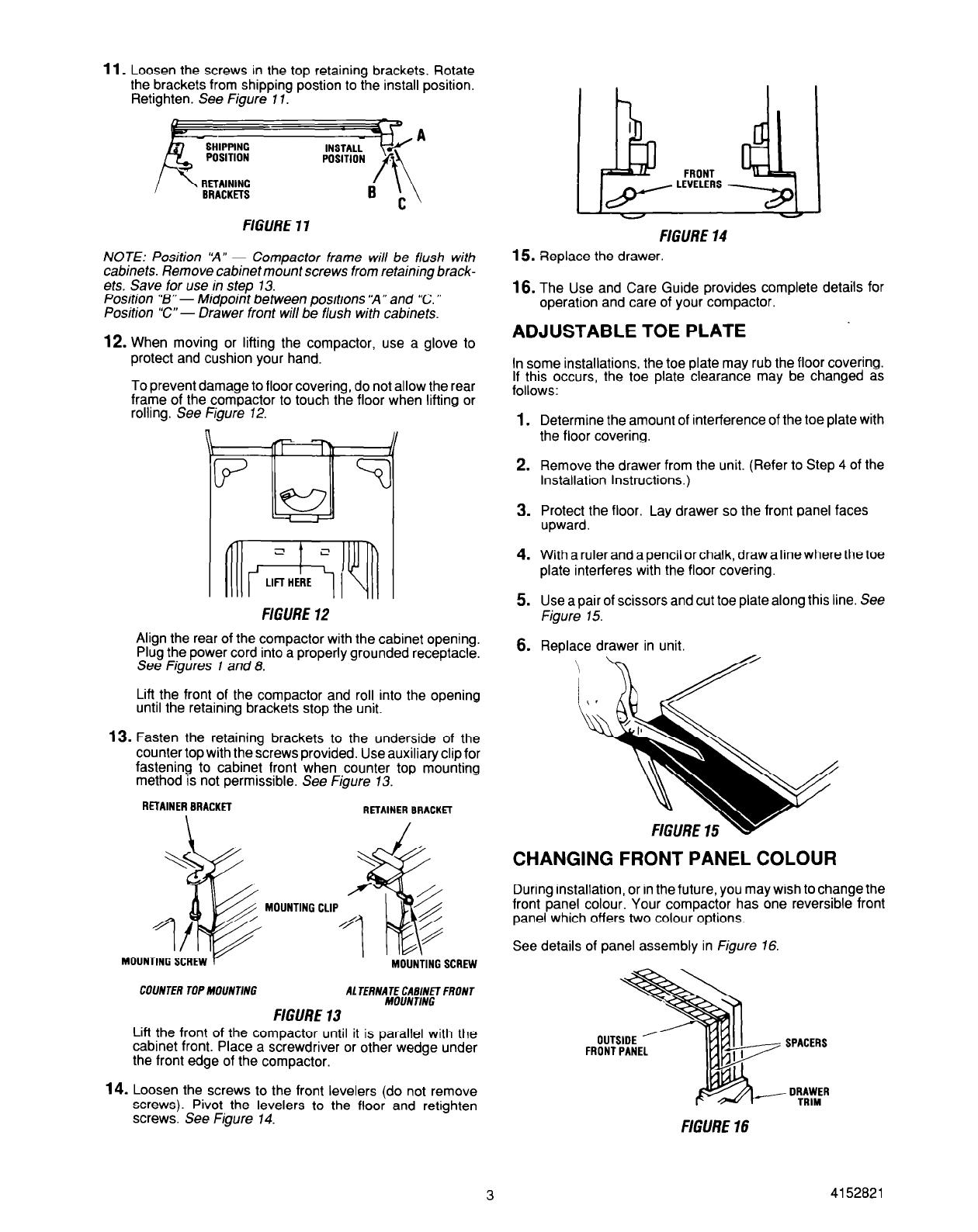
11.
Loosen the screws in the top retaining brackets. Rotate
the brackets from shipping postion to the install position.
Retighten. See Figure 11.
/ ’
RETAINING
EIRACKmS
FIGURE 11
NOTE: Position ‘A” - Compactor frame will be flush with
cabinets. Remove cabinet mount screws from retaining brack-
ets. Save for use in step 73.
Position “B” - Midpoint between positions ‘A” and ‘C. ”
Position “C” - Drawer front will be flush with cabinets.
12.
When moving or lifting the compactor, use a glove to
protect and cushion your hand.
To prevent damage to floor covering, do not allow the rear
frame of the compactor to touch the floor when lifting or
rolling. See Figure 12.
FIGURE 12
Align the rear of the compactor with the cabinet opening.
Plug the power cord into a properly grounded receptacle.
See Figures 7 and 8.
Lift the front of the compactor and roll into the opening
until the retaining brackets stop the unit.
13.
Fasten the retaining brackets to the underside of the
counter top with the screws provided. Use auxiliary clip for
fastening to cabinet front when counter top mounting
method is not permissible. See Figure 13.
RETAINER BRACKET
RETAINER BRACKfl
MOUNTING SCREW
COUNTER TOP MOUNTING
AL TERNATE CABINET FRONT
MOUNTING
FIGURE 13
Lift the front of the compactor until it is parallel with the
cabinet front. Place a screwdriver or other wedge under
the front edge of the compactor.
14.
Loosen the screws to the front levelers (do not remove
screws). Pivot the levelers to the floor and retighten
screws. See Figure 14.
FIGURE 14
15. Replace the drawer.
16.
The Use and Care Guide provides complete details for
operation and care of your compactor.
ADJUSTABLE TOE PLATE
In some installations, the toe plate may rub the floor covering.
If this occurs, the toe plate clearance may be changed as
follows:
1.
Determine the amount of interference of the toe plate with
the floor covering.
2. Remove the drawer from the unit. (Refer to Step 4 of the
Installation Instructions.)
3. ;;;;;;,the floor. Lay drawer so the front panel faces
4. With a ruler and a pencil or chalk, draw a line where the toe
plate interferes with the floor covering.
5. Use a pair of scissors and cut toe plate along this line. See
Figure 15.
6.
Replace drawer in unit.
CHANGING FRONT PANEL COLOUR
During installation, or in the future, you may wish to change the
front panel colour. Your compactor has one reversible front
panel which offers two colour options.
See details of panel assembly in Figure 16.
3
FIGURE 16
4152821
CAUTION: The panels have cut metal edges. Handle care-
fully to avoid cuts to hands and scratches on panels.
To change the front panel colour:
1.
Remove the drawer from the unit. (See Step 4 of the
Installation Instructions.)
2. Remove handle by removing the screws at the top inside
of the drawer.
3.
Remove one spacer.
4. Remove outside front panel by carefully pulling it up.
5. Select the colour you wish to have showing and carefully
push the panel in the drawer trim.
6.
Replace the spacer.
7. Replace the handle with the screws removed in Step 2
above.
8.
‘Replace the drawer.
CAUTION:
REPLACE HANDLE BEFORE OPERATING
COMPACTOR TO AVOID INJURY FROM MOVING PARTS.
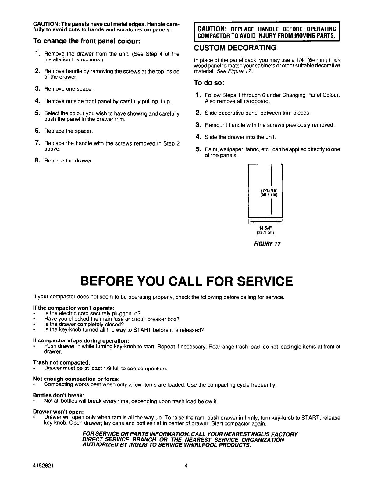
CUSTOM DECORATING
In place of the panel back, you may use a l/4” (64 mm) thick
wood panel to match your cabinets or other suitabledecorative
material. See Figure 17.
To do so:
1.
Follow Steps 1 through 6 under Changing Panel Colour.
Also remove all cardboard.
2. Slide decorative panel between trim pieces.
3. Remount handle with the screws previously removed.
4. Slide the drawer into the unit.
5.
Paint, wallpaper, fabric, etc., can be applied directly to one
of the panels.
t
22.i5n6”
(58.3 cm)
1
1 -
- ,
M-518"
(37.1
cm)
FIGURE 17
BEFORE YOU CALL FOR SERVICE
If your compactor does not seem to be operating properly, check the following before calling for set-vice.
If the compactor won’t operate:
.
Is the electric cord securely plugged in?
.
Have you checked the main fuse or circuit breaker box?
.
Is the drawer completely closed?
.
Is the key-knob turned all the way to START before it is released?
If compactor stops during operation:
.
Push drawer in while turning key-knob to stat-t. Repeat if necessary. Rearrange trash load-do not load rigid items at front of
drawer.
Trash not compacted:
.
Drawer must be at least l/3 full to see compaction.
Not enough compaction or force:
.
Compacting works best when only a few items are loaded. Use the compacting cycle frequently.
Bottles don’t break:
.
Not all bottles will break every time, depending upon trash load below it.
Drawer won’t open:
.
Drawer will open only when ram is all the way up. To raise the ram, push drawer in firmly; turn key-knob to START; release
key-knob. Open drawer; lay cans and bottles flat in center of drawer. Start compactor again.
FOR SERVICE OR PARTS INFORMATION, CALL YOUR NEARESTINGLIS FACTORY
DIRECT SERVICE BRANCH OR THE NEAREST SERVICE ORGANIZATION
AUTHORIZED BY INGLIS TO SERVICE WHIRLPOOL PRODUCTS.
4152821
4
/