Page is loading ...

Keep these important operating instructions.
Check www.meyersound.com for updates.
OPERATING INSTRUCTIONS
CINE STUDIO
HMS Cinema Surround Loudspeaker (IntelligentDC)
HMS-5, HMS-10, HMS-12, and HMS-15

ii
© 2016
Meyer Sound. All rights reserved.
HMS Operating Instructions, PN 05.198.005.01 A
The contents of this manual are furnished for informational purposes only, are subject to change without notice, and should not be con-
strued as a commitment by Meyer Sound Laboratories Inc. Meyer Sound assumes no responsibility or liability for any errors or inaccura-
cies that may appear in this manual. Except as permitted by applicable copyright law, no part of this publication may be reproduced,
stored in a retrieval system, or transmitted, in any form or by any means, electronic, mechanical, recording or otherwise, without prior writ-
ten permission from Meyer Sound.
Compass RMS, RMS, and all alpha-numeric designations for Meyer Sound products and accessories are trademarks of Meyer Sound.
Acheron, Compass, Meyer Sound, the Meyer Sound wave logo, and Thinking Sound are registered trademarks of Meyer Sound Laborato-
ries Inc. (Reg. U.S. Pat. & Tm. Off.). All third-party trademarks mentioned herein are the property of their respective trademark holders.

iii
CONTENTS
Chapter 1: Introduction 5
How to Use This Manual 5
HMS Cinema Surround Loudspeaker 5
MPS-488HP IntelligentDC High-Power Eight-Channel power Supply 8
Chapter 2: HMS Loudspeakers 9
Single-Channel Input Connector (HMS-5, HMS-10, and HMS-12) 9
Dual-Channel Input Connectors (HMS-15) 9
Current Draw and Cable Requirements for HMS Loudspeakers 10
Belden 1502 Cable (or Equivalent) 10
Long Cable Runs with Separate Cable for DC Power and Audio 11
On/Status LED 11
Pad Switch (HMS-10 Only) 12
Chapter 3: Powering HMS Loudspeakers 13
Powering HMS Loudspeakers 13
Configuring the MPS-488HP in Compass RMS 14
Chapter 4: HMS Mounting Options 17
Important Safety Considerations! 17
HMS Mounting Options 17
Chapter 5: Removing HMS Grille Frames 21
Removing HMS-12 and HMS-15 Grille Frames 21
Appendix A: HMS Accessories 23
Appendix B: Assembling Loudspeaker Cables 25
Appendix C: HMS Specifications 27

iv

5
CHAPTER 1: INTRODUCTION
HOW TO USE THIS MANUAL
Make sure to read these instructions in their entirety before
configuring a Meyer Sound loudspeaker system. In particular,
pay close attention to material related to safety issues.
As you read these instructions, you will encounter the follow-
ing icons for notes, tips, and cautions:
NOTE: A note identifies an important or useful
piece of information relating to the topic under
discussion.
TIP: A tip offers a helpful tip relevant to the topic
at hand.
CAUTION: A caution gives notice that an action
may have serious consequences and could
cause harm to equipment or personnel, or could
cause delays or other problems.
Information and specifications are subject to change.
Updates and supplementary information are available at
www.meyersound.com
.
Meyer Sound Technical Support is available at:
■ Tel: +1 510 486.1166
■ Tel: +1 510 486.0657 (after hours support)
■ Web: www.meyersound.com/support
■ Email: [email protected]
HMS CINEMA SURROUND LOUDSPEAKER
The HMS cinema surround loudspeaker is optimized for use
in cinemas, high-end private theatres, screening rooms, and
other surround applications. Designed to complement Meyer
Sound’s Acheron™ screen channel loudspeakers, the self-
powered HMS maintains a wide dynamic range, exceptional
fidelity, and precise clarity during the most demanding of dig-
ital soundtracks. Boasting a wide frequency range and a gen-
erous linear peak SPL with very low distortion, the HMS
delivers the full intensity and nuance of cinema surround
channels to every listener without compromise.
The HMS cinema surround loudspeaker is available in five
models: HMS-5, HMS-10, HMS-12, HMS-15, and
HMS-15AC, ranging in size, weight, driver size, and power to
accommodate a wide range of venues and applications. The
proprietary long-excursion cone drivers and diaphragm com-
pression drivers are driven by an onboard amplifier that
includes an active crossover, driver protection circuitry, and
correction filters for flat phase and frequency response. A
constant-directivity horn provides uniform, full-range, con-
sistent coverage.
The HMS-5, HMS-10, HMS-12, and HMS-15 are equipped
with IntelligentDC technology and receive DC power and bal-
anced audio from composite Phoenix™ 5-pin connectors.
Powering the loudspeakers from an external DC source elim-
inates the need for AC conduits while preserving the advan-
tages of self-powered systems. IntelligentDC loudspeakers
require an MPS-488HP external power supply. The single-
space 19-inch rack unit distributes DC power and balanced
audio to up to eight HMS-5, HMS-10, or HMS-12 loudspeak-
!
HMS-10 Cinema Surround Loudspeaker (With Grille)

CHAPTER 1: INTRODUCTION
6
ers, or up to four HMS-15 loudspeakers. Composite multi-
conductor cables, such as Belden
®
1502 or equivalent, can
deliver both DC power and balanced audio to loudspeakers
at cable lengths up to 150 feet with just 1 dB of loss in peak
SPL using 18 AWG wire. Longer cable runs are possible with
heavier gauges. The MPS-488HP is optionally available with
an RMS™ remote monitoring system module for monitoring
voltage and current draw for its attached loudspeakers from
a Mac
®
or Windows
®
-based computer.
The HMS-15AC is an AC-powered version of the HMS-15. Its
Intelligent AC™ power supply provides automatic voltage
selection, EMI filtering, soft current turn-on, and surge sup-
pression. The HMS-15AC is optionally available with its own
onboard RMS remote monitoring system module for compre-
hensive monitoring of loudspeaker parameters from a Mac or
Windows-based computer.
The versatile HMS can be suspended or mounted on walls or
ceilings at fixed or adjustable angles with optional half-yoke,
U-bracket, or wall-mount brackets, allowing it to be deployed
per the requirements of any surround application or immer-
sive cinema format.
Meyer Sound’s industry-leading self-powered technology not
only delivers unparalleled and consistent audio fidelity but
also simplifies installation, whether designing new rooms
from scratch or adding surround channels to existing instal-
lations. The HMS cabinet features a black textured finish and
an acoustically transparent, detachable, black cloth grille that
blend smartly with any theatre decor.
These operating instructions document the following HMS
loudspeakers:
■ HMS-5 compact cinema surround loudspeaker
■ HMS-10 cinema surround loudspeaker
■ HMS-12 high-power cinema loudspeaker
■ HMS-15 high-power cinema loudspeaker
NOTE: For the sake of brevity, when referring to
these loudspeakers collectively, this document
will refer to them as HMS loudspeakers.
NOTE: The AC-powered HMS-15AC is not doc-
umented in these operating instructions. For
information on it, refer to the HMS-15AC Operating
Instructions (PN 05.242.005.01).
HMS-5 Compact Cinema Surround
Loudspeaker
The HMS-5 compact cinema loudspeaker includes two
5-inch low-frequency, long-excursion cone drivers, and one
2-inch diaphragm high-frequency compression driver on a
symmetrical, constant-directivity 80-degree horn. The loud-
speaker is powered by a 3-channel amplifier with an active
crossover. The cabinet is constructed of multi-ply hardwood
and includes 3.94 inches x 3.94 inches (100 mm x 100 mm)
rear attachment points for optional mounting hardware.
HMS-10 Cinema Surround Loudspeaker
The HMS-10 cinema loudspeaker includes one 10-inch low-
frequency, long-excursion cone driver, and one 2-inch dia-
phragm high-frequency compression driver on a symmetri-
cal, constant-directivity 80-degree horn. The loudspeaker is
powered by a 2-channel amplifier with an active crossover.
The cabinet is constructed of multi-ply hardwood and
includes 3.94 inches x 3.94 inches (100 mm x 100 mm) rear
attachment points for optional mounting hardware.
HMS-5 Compact Cinema Surround Loudspeaker (Without Grille)
HMS-10 Cinema Surround Loudspeaker (Without Grille)

HMS OPERATING INSTRUCTIONS
7
HMS-12 High-Power Cinema Surround
Loudspeaker
The HMS-12 high-power cinema loudspeaker includes one
12-inch low-frequency, long-excursion cone driver, and one
3-inch diaphragm high-frequency compression driver on a
symmetrical, constant-directivity 100-degree horn. The loud-
speaker is powered by a 2-channel amplifier with an active
crossover. The cabinet is constructed of multi-ply hardwood
and includes 3.94 inches x 3.94 inches (100 mm x 100 mm)
rear attachment points for optional mounting hardware.
HMS-15 High-Power Cinema Surround
Loudspeaker
The HMS-15 high-power cinema loudspeaker includes one
15-inch low-frequency, long-excursion cone driver, and one
3-inch diaphragm high-frequency compression driver on a
symmetrical, constant-directivity 80-degree horizontal by
50-degree vertical horn. The loudspeaker is powered by a 2-
channel amplifier with an active crossover. The cabinet is
constructed of multi-ply hardwood and includes 5.00 inches
x 2.75 inches (127 mm x 70 mm) rear attachment points and
side attachment points with 3/8”-16 threads for optional
mounting hardware.
HMS-12 High-Power Cinema Surround Loudspeaker (Without Grille)
HMS-15 High-Power Cinema Surround Loudspeaker (Without Grille)

CHAPTER 1: INTRODUCTION
8
MPS-488HP INTELLIGENTDC HIGH-POWER
EIGHT-CHANNEL POWER SUPPLY
HMS loudspeakers require an external MPS-488HP
IntelligentDC power supply. The single-space 19-inch rack
unit distributes DC power and balanced audio to up to eight
HMS-5, HMS-10, or HMS-12 loudspeakers, or up to four
HMS-15 loudspeakers. Composite multiconductor cables,
such as Belden 1502 or equivalent, can deliver both DC
power and balanced audio to loudspeakers at cable lengths
up to 150 feet with just 1 dB of loss in peak SPL using
18 AWG wire. Longer cable runs are possible with heavier
gauges. Meyer Sound’s RMS remote monitoring system is
optionally available for the MPS-488HP.
CAUTION: Disconnect the mains plug or power
off the MPS-488HP before disconnecting its
power cord.
TIP: For complete information on using the
MPS-488HP IntelligentDC power supply, refer to
the MPS-488HP Operating Instructions
(PN 05.205.005.01).
MPS-488HP IntelligentDC Power Supply
!

9
CHAPTER 2: HMS LOUDSPEAKERS
SINGLE-CHANNEL INPUT CONNECTOR
(HMS-5, HMS-10, AND HMS-12)
The HMS-5, HMS-10, and HMS-12 loudspeakers receive DC
power and balanced audio from a single Phoenix 5-pin male
Input connector. The connector includes two pins for DC
power (positive and negative) and three pins for balanced
audio (positive, negative, and shield). The pins are clearly
labeled on the HMS user panel. To function properly, the
HMS-5, HMS-10, and HMS-12 require an MPS-488HP Intel-
ligentDC power supply (one channel output per loudspeaker).
The MPS-488HP can power up to eight single-channel HMS
loudspeakers.
Single-channel HMS loudspeakers ship with one Phoenix
5-pin female cable mount connector for assembling loud-
speaker cables. A single composite cable (such as
Belden 1502 or equivalent) can be used to route DC power
and balanced audio to the HMS loudspeaker. For more infor-
mation, see “Belden 1502 Cable (or Equivalent)” on page 10
and Appendix B, “Assembling Loudspeaker Cables.”
CAUTION: When wiring HMS loudspeaker
cables, it is extremely important that each pin
be wired correctly. Make sure the 48 V DC from the
external power supply is wired directly (and only) to
the 48 V DC pins on the loudspeaker connector, and
that the polarity is observed (negative to negative,
positive to positive) to avoid damage to the loud-
speaker. In addition, make sure that audio pins are
wired correctly; polarity reversals for audio signals
affect system performance.
DUAL-CHANNEL INPUT CONNECTORS
(HMS-15)
The HMS-15 loudspeaker receives DC power and balanced
audio from two Phoenix 5-pin male Input connectors. Each
connector includes two pins for DC power (positive and neg-
ative) and three pins for balanced audio (positive, negative,
and shield). The pins are clearly labeled on the HMS-15 user
panel. To function properly, the HMS-15 requires an
MPS-488HP IntelligentDC power supply (two channel out-
puts per loudspeaker). The MPS-488HP can power up to four
HMS-15 loudspeakers.
The HMS-15 must be connected to a channel output pair
(1–2, 3–4, 5–6, or 7–8) of the MPS-488HP using two sepa-
rate composite cables. When successfully connected and
receiving the required voltage, both Input LEDs for the
HMS-15 turn solid green. Identical audio signals can be sent
to the two inputs with no additional gain and no adverse
effect. Sending different audio signals to the two inputs is
not recommended and could cause one signal to be heard
in the background.
NOTE: If the HMS-15 does not sense power
from both inputs (both Input LEDs lit) then it will
not output audio.
HMS-15 loudspeakers ship with two Phoenix 5-pin female
cable mount connectors for assembling loudspeaker cables.
Separate composite cables (such as Belden 1502 or equiva-
lent) must be used to route DC power and balanced audio to
the two inputs for the HMS-15 loudspeaker. For more infor-
mation, see “Belden 1502 Cable (or Equivalent)” on page 10
and Appendix B, “Assembling Loudspeaker Cables.”
Single-Channel Input Connector (HMS-5, HMS-10, and HMS-12)
!
Dual-Channel Input Connectors (HMS-15)

CHAPTER 2: HMS LOUDSPEAKERS
10
CAUTION: When wiring HMS loudspeaker
cables, it is extremely important that each pin
be wired correctly. Make sure the 48 V DC from the
external power supply is wired directly (and only) to
the 48 V DC pins on the loudspeaker connector, and
that the polarity is observed (negative to negative,
positive to positive) to avoid damage to the loud-
speaker. In addition, make sure that audio pins are
wired correctly; polarity reversals for audio signals
affect system performance.
CURRENT DRAW AND CABLE REQUIRE-
MENTS FOR HMS LOUDSPEAKERS
DC current draw for HMS loudspeakers is dynamic and fluc-
tuates as operating levels change. Cabling between HMS
loudspeakers and their external power supply adds resis-
tance and hence causes a voltage drop at the loudspeakers.
Because lower DC voltages compromise amplifier perfor-
mance (peak SPL), and in some cases frequency response,
cable resistance should be kept to a minimum.
Cable Lengths and Cable Gauges
Cable lengths up to 150 feet between HMS loudspeakers and
their external power supply are supported with only 1 dB of
peak SPL loss using 18 AWG wire. Longer cable lengths are
possible with heavier wire gauges (see Table 1 and Table 2).
NOTE: The total cable resistance between HMS
loudspeakers and their external power supply
should not exceed 2 ohms.
NOTE: For long cable runs, you can use a large
cable gauge for DC power and a separate bal-
anced audio cable for audio. For more information,
see “Long Cable Runs with Separate Cable for DC
Power and Audio” on page 11.
Calculating the Maximum Cable Length
The maximum cable length for an HMS loudspeaker can be
calculated with the following formula:
maximum length = 2 ohms / (2 * cable resistance)
For example, the maximum length of an 18 AWG cable with a
resistance of 0.00636 is 157.2 feet (2 / (2 * 0.00636)).
BELDEN 1502 CABLE (OR EQUIVALENT)
The most convenient method of wiring HMS loudspeaker
cables is with a multiconductor cable such as Belden 1502,
which has dedicated conductors for DC power and bal-
anced audio in a single jacket. When wiring loudspeaker
cables with Belden 1502 (or equivalent), use the conventions
in Table 3. The red and black wires are 18 AWG, thicker than
the other three wires, and should be used for DC power
(cable lengths up to 150 feet are possible with just 1 dB of
peak SPL loss). The blue, white, and shield drain wires
should be used for audio.
CAUTION: When wiring HMS loudspeaker
cables, it is extremely important that each pin
be wired correctly. Make sure the 48 V DC from the
external power supply is wired directly (and only) to
the 48 V DC pins on the loudspeaker connector, and
Table 1: HMS Loudspeaker Cable Lengths (AWG)
Cable Gauge Resistance
(Ohms/ft)
Approximate
Max. Length
12 AWG 0.0016 600 ft
14 AWG 0.00253 375 ft
16 AWG 0.00402 237 ft
18 AWG 0.00636 150 ft
20 AWG 0.01008 87 ft
Table 2: HMS Loudspeaker Cable Lengths (European)
Cable Gauge Resistance
(Ohms/m)
Approximate
Max. Length
2.50 mm
2
0.0052 157 m
1.50 mm
2
0.01076 87 m
1.00 mm
2
0.02087 45 m
0.75 mm
2
0.03307 27 m
!
Belden 1502 Composite Cable
Table 3: HMS Loudspeaker Cables with Belden 1502
Wire Signal Gauge
Black DC power (–) 18 AWG
Red DC power (+) 18 AWG
Shield drain Audio shield 24 AWG
Blue Audio signal (–) 22 AWG
White Audio signal (+) 22 AWG
Pin 1 DC power (–)
Pin 2 DC power (+)
Pin 3 Audio shield
Pin 4 Audio signal (–)
Pin 5 Audio signal (+)
!

HMS OPERATING INSTRUCTIONS
11
that the polarity is observed (negative to negative,
positive to positive) to avoid damage to the loud-
speaker. In addition, make sure that audio pins are
wired correctly; polarity reversals for audio signals
affect system performance.
NOTE: For more information on cable assem-
bly, refer to Appendix B, “Assembling Loud-
speaker Cables.”
NOTE: For a complete list of available cables
and cable accessories from Meyer Sound, refer
to Appendix A, “HMS Accessories.”
LONG CABLE RUNS WITH SEPARATE CABLE
FOR DC POWER AND AUDIO
For installations where Belden 1502 is not feasible, or for
installations that require cable runs longer than 150 feet, you
can use separate cables for DC power and balanced audio: a
large-gauge cable for DC and a high-quality, balanced audio
cable for audio. The separate cables attach to the Phoenix
connector at the loudspeaker as shown in Figure 1. Cable
runs longer than 150 feet for DC power require cable gauges
larger than 18 AWG; for more information, see “Cable
Lengths and Cable Gauges” on page 10.
ON/STATUS LED
The HMS user panel includes an On/Status LED that indi-
cates whether the loudspeaker is operating normally (green),
limiting or overheating (yellow), or clipping (red).
NOTE: The HMS-15 also includes two Input
LEDs that indicate, when solid green, when the
inputs are receiving voltage from the MPS-488HP.
Normal Operation (Green)
When powering on the HMS loudspeaker, the following
startup events occur and are indicated by the On/Status LED:
1. The On/Status LED flashes multiple colors during its
power-on sequence.
2. The LED turns solid green, indicating the power-on
sequence has completed and the loudspeaker is ready to
reproduce audio.
3. The LED remains green but is dimmed to eliminate any
undesired glow in darkened theatres.
CAUTION: If after the power-on sequence the
On/Status LED does not turn solid green (instead
flashes multiple colors or stays solid red) and the HMS
loudspeaker does not output audio, the loudspeaker
has encountered an error and may need to be serviced.
Contact Meyer Sound Technical Support.
NOTE: All three LEDs for the HMS-15 (Input 1,
Input 2, and On/Status) must turn solid green
before it will output audio. If some or all of the HMS-15
LEDs remain unlit, or not green, verify the cabling to
the MPS-488HP.
Limiting (Yellow)
The On/Status LED turns yellow to indicate limiting. When the
LED is solid yellow, limiting is engaged for the high-frequency
channel. When the LED flashes yellow (on and off), limiting is
engaged for the low-frequency channel.
When engaged, limiting not only protects the drivers but also
prevents signal peaks from causing excessive distortion in
the amplifier channels, thereby preserving headroom and
maintaining smooth frequency response at high levels. When
levels return to normal, below the limiter thresholds, limiting
ceases and the On/Status LED returns to green.
The HMS loudspeaker performs within its acoustical specifi-
cations at normal temperatures when the On/Status LED is
green, or when limiting is not continuous. If limiting activity is
continuous, the loudspeaker is nearing the limits of its oper-
ating capabilities where:
■ Increases to the input level have no effect
■ Distortion increases due to clipping
■ Drivers are subjected to excessive heat and excursion,
thereby compromising their lifespan
Figure 1: Separate Cables for DC Power and Balanced Audio
Audio
cable
DC
cable
Pin 1 DC power (–)
Pin 2 DC power (+)
Pin 3 Audio shield
Pin 4 Audio signal (–)
Pin 5 Audio signal (+)
!

CHAPTER 2: HMS LOUDSPEAKERS
12
CAUTION: Continuous limiting indicates that a
safe, optimum level has been exceeded. If the
HMS loudspeakers in a cinema installation begin to
limit before reaching the desired SPL, consider adding
more units to the system.
Operating Temperature
The On/Status LED also turns solid yellow when the HMS
loudspeaker’s internal temperature reaches a certain level,
indicating the unit is reaching its maximum heat dissipation.
When the On/Status LED is yellow, a reduction in SPL is rec-
ommended. While the loudspeaker will continue to operate
while the LED is yellow, the limiter threshold is lowered (caus-
ing the output level to also be reduced) to prevent the loud-
speaker from overheating. When the loudspeaker’s internal
temperature returns to a normal level, the On/Status LED
returns to green and the limiter threshold returns to normal.
Amplifier Cooling
HMS loudspeakers rely solely on natural convection for cool-
ing from air flowing over their heat sinks. The efficient ampli-
fier and heat sink design keeps temperatures low, even when
units are operated at high ambient temperatures and driven
continuously at high output levels.
Clipping on Input (Red)
The On/Status turns red when the loudspeaker’s input stage
clips, causing the amplifier to overload. When the On/Status
LED is red, the source level should be reduced to avoid dis-
tortion and to avoid overloading the amplifier.
CAUTION: If the On/Status LED turns solid red
and the loudspeaker continues to output audio,
though at reduced levels, the loudspeaker’s voltage
may have dropped below 25 V DC. When these con-
ditions are encountered, operation of the loudspeaker
should cease and its power supply and cabling should
be verified.
PAD SWITCH (HMS-10 ONLY)
The HMS-10 user panel includes a Pad switch that, when
enabled, reduces the loudspeaker’s internal gain by 7.5 dB,
thereby lowering the loudspeaker’s noise floor. This reduces
noise generated from audio sources upstream from the loud-
speaker and is especially useful for close-proximity listening.
NOTE: When the Pad switch is enabled (set to
Pad), to achieve the linear peak SPL for the
loudspeaker, the gain for the processor driving the
loudspeaker must be increased by 7.5 dB.
!
!
HMS-10 Pad Switch

13
CHAPTER 3: POWERING HMS LOUDSPEAKERS
HMS loudspeakers require an external MPS-488HP
IntelligentDC power supply. The single-space 19-inch rack
unit distributes DC power and balanced audio to up to eight
HMS-5, HMS-10, or HMS-12 loudspeakers, or up to four
HMS-15 loudspeakers. Composite multiconductor cables,
such as Belden 1502 or equivalent, can deliver both DC
power and balanced audio to loudspeakers at cable lengths
up to 150 feet with just 1 dB of loss in peak SPL using
18 AWG wire. Longer cable runs are possible with heavier
gauges. Meyer Sound’s RMS remote monitoring system is
optionally available for the MPS-488HP.
CAUTION: Disconnect the mains plug or power
off the MPS-488HP before disconnecting its
power cord.
TIP: For complete information on using the
MPS-488HP IntelligentDC power supply, refer to
the MPS-488HP Operating Instructions
(PN 05.205.005.01).
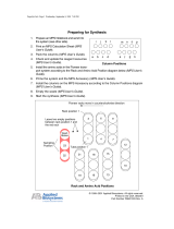
POWERING HMS LOUDSPEAKERS
NOTE: The MPS-488HP can power up to eight
single-channel HMS loudspeakers (HMS-5,
HMS-10, and HMS-12), or up to four dual-channel
HMS-15 loudspeakers.
To power HMS loudspeakers with the MPS-488HP:
1. Power off the MPS-488HP.
2. Connect audio sources (from a mixer or processor) to the
MPS-488HP channel inputs. Use balanced XLR cables.
3. Use the MPS-488HP Link switches to route channel
inputs to the desired channel outputs. For information on
the MPS-488HP Link switches, refer to the MPS-488HP
Operating Instructions (PN 05.205.005.01).
4. Connect HMS loudspeakers to the MPS-488HP channel
outputs. Use composite cables (such as Belden 1502 or
equivalent) wired for both DC power and balanced audio
and outfitted with the appropriate connectors.
■ To power single-channel HMS loudspeakers (HMS-5,
HMS-10, and HMS-12), connect each loudspeaker to a
single channel output with a single composite cable. The
MPS-488HP can power up to eight single-channel HMS
loudspeakers.
!
MPS-488HP with Eight HMS-10 Loudspeakers
MPS-488HP

CHAPTER 3: POWERING HMS LOUDSPEAKERS
14
■ To power dual-channel HMS-15 loudspeakers, connect
each loudspeaker to a channel output pair (1–2, 3–4,
5–6, or 7–8) with two separate composite cables. The
MPS-488HP can power up to four dual-channel HMS-15
loudspeakers.
CAUTION: When powering HMS-15 loudspeak-
ers, you must use two separate composite
cables connected to an MPS-488HP channel output
pair (1–2, 3–4, 5–6, or 7–8). Do not use a single cable
to deliver power to the HMS-15’s two Input connec-
tors. Never, in any manner, combine the signals from
two MPS-488HP channel outputs, either at the power
supply (source) or the loudspeaker (destination).
CAUTION: Make sure loudspeaker cables are
wired correctly. For details on assembling loud-
speaker cables, refer to Appendix B, “Assembling
Loudspeaker Cables.”
TIP: You can use separate cables for HMS loud-
speaker connections: a 2-conductor cable for
DC power and a 3-conductor cable for balanced
audio, both attached to a single Phoenix connector on
each cable end. This allows you to use a larger gauge
for the DC cable so you can achieve longer cable runs
(see “Long Cable Runs with Separate Cable for DC
Power and Audio” on page 11).
5. Power on the MPS-488HP and monitor the LEDs on the
front panel to verify connections. For information on the
MPS-488HP LEDs, refer to the MPS-488HP Operating
Instructions (PN 05.205.005.01).
6. Monitor the HMS loudspeaker LEDs to verify they are
receiving power.
■ For single-channel HMS loudspeakers (HMS-5, HMS-10,
and HMS-12), make sure the On/Status LED turns solid
green after powering on the loudspeakers.
■ For dual-channel HMS-15 loudspeakers, make sure the
two Input LEDs and On/Status LED turn solid green after
powering on the loudspeakers.
7. Enable output from the audio sources (from the mixer or
processor) connected to the MPS-488HP.
CONFIGURING THE MPS-488HP IN COMPASS
RMS
IntelligentDC loudspeakers can connect to RMS networks via
the MPS-488HP external supply (when equipped with the
factory-installed RMS option). Up to eight single-channel
HMS loudspeakers (HMS-5, HMS-10, and HMS-12) or up to
four dual-channel HMS-15 loudspeakers can be connected
to the MPS-488HP with their voltage and DC current moni-
tored in Compass RMS™.
NOTE: In order for the MPS-488HP to report the
correct voltage and current draw for the
HMS-15 to RMS, the HMS-15 must be connected to
an odd-even output pair (1–2, 3–4, 5–6, or 7–8) using
two separate composite cables.
To configure the MPS-488HP in Compass RMS:
1. Make sure the MPS-488HP power supply is powered on
and connected to the RMS network.
2. In Compass, click the RMServer > Network tab.
MPS-488HP with Four HMS-15 Loudspeakers
MPS-488HP
!
!

HMS OPERATING INSTRUCTIONS
15
3. In the Device list, right-click the MPS-488HP powering
the HMS loudspeakers and choose Edit Loudspeaker
Inventory.
4. In the Edit Loudspeaker Inventory dialog box, click in the
Product column and select the HMS loudspeaker model
connected to each MPS-488HP channel output.
■ Single-channel HMS loudspeakers (HMS-5, HMS-10, and
HMS-12) occupy a single channel output.
■ Dual-channel HMS-15 loudspeakers automatically
occupy two channel outputs.
5. Enter a name and serial number for each HMS loud-
speaker.
6. Click OK to save and upload the MPS-488HP loud-
speaker inventory. Once the MPS-488HP device is added
to an RMS page, the page displays the voltage and cur-
rent draw for the connected HMS loudspeakers.

CHAPTER 3: POWERING HMS LOUDSPEAKERS
16

17
CHAPTER 4: HMS MOUNTING OPTIONS
IMPORTANT SAFETY CONSIDERATIONS!
When mounting Meyer Sound loudspeakers, the following precautions should always be observed:
■ All Meyer Sound products must be used in accordance
with local, state, federal, and industry regulations. It is the
owner’s and user’s responsibility to evaluate the reliability
of any rigging or mounting method for their application.
Rigging should only be carried out by experienced profes-
sionals.
■ Use mounting and rigging hardware that has been rated
to meet or exceed the weight being hung.
■ Make sure to attach mounting hardware to the building’s
structural components (studs or joists), and not just to the
wall surface. Verify that the building’s structure and the
anchors used for the installation will safely support the
total weight of the mounted loudspeakers.
■ Use mounting hardware appropriate for the surface where
the loudspeaker will be installed.
■ Make sure bolts are tightened securely. Meyer Sound rec-
ommends using Loctite on bolt threads and safety cables.
■ Inspect mounting and rigging hardware regularly. Imme-
diately replace any worn or damaged components.
HMS MOUNTING OPTIONS
Table 4 list the mounting options available for HMS loudspeakers. All mounting options are rated for mounting a single HMS
loudspeaker with a 7:1 safety factor. For more information, refer to the installation instructions included with the mounting
hardware.
Table 4: HMS Mounting Options
Model (Part Number) Features Maximum Uptilt/Downtilt Weight Rated for
Overhead
Mounting
FMB-HMS Fixed Mount Bracket
(PN 40.198.040.01)
Mounts HMS loudspeakers (all
models) on walls at a fixed 0-
degree angle. The fixed bracket
mounts cabinets 0.87 inches
from the wall.
■ HMS-5: 0°
■ HMS-10: 0°
■ HMS-12: 0°
■ HMS-15: 0°
■ HMS-15AC: 0°
3.1 lbs
(1.4 kg)
No

CHAPTER 4: HMS MOUNTING OPTIONS
18
AMB-HMS Adjustable Mount Bracket
(PN 40.198.041.01)
Mounts HMS loudspeakers (all
models) on walls with uptilt or
downtilt. The available tilt
depends on the HMS loud-
speaker model mounted. When
installed with no tilt, the bracket
mounts cabinets 2.24 inches
from the wall.
■ HMS-5: +5°/–16°
■ HMS-10: +5°/–16°
■ HMS-12: +5°/–12°
■ HMS-15: +5°/–10°
■ HMS-15AC: +5°/–10°
Note: Wider downtilt may be
possible depending on the
building’s structural compo-
nents and mounting surface.
4.2 lbs
(1.9 kg)
No
HY-HMS Half Yoke
(PN 40.227.031.01)
Suspends HMS-5, HMS-10, and
HMS-12 loudspeakers with a full
range of tilt (360°). The yoke can
attach directly to ceilings or can
accept “C” or “G” hanging
clamps with standard 1/2-inch or
12 mm bolts.
■ HMS-5: 360°
■ HMS-10: 360°
■ HMS-12: 360°
12.4 lbs
(5.6 kg)
Yes
Table 4: HMS Mounting Options
Model (Part Number) Features Maximum Uptilt/Downtilt Weight Rated for
Overhead
Mounting

HMS OPERATING INSTRUCTIONS
19
HY-HMS-15 Half Yoke
(PN 40.242.035.01)
Suspends HMS-15 and
HMS-15AC loudspeakers with a
full range of tilt (360°). The yoke
can attach directly to ceilings or
can accept “C” or “G” hanging
clamps with standard 1/2-inch or
12 mm bolts.
■ HMS-15: 360°
■ HMS-15AC: 360°
7.6 lbs
(3.4 kg)
Yes
MUB-HMS U-Bracket
(PN 40.227.032.01)
Mounts HMS-5, HMS-10, and
HMS-12 loudspeakers on walls
and ceilings with uptilt or down-
tilt. The U-bracket includes three
loudspeaker attachment points
for placing the loudspeaker
closer or further from the mount-
ing surface. The available tilt is
determined by which HMS loud-
speaker model is mounted and
which attachment points are
used.
■ HMS-5: +60°/–43°
■ HMS-10: +32°/–25°
■ HMS-12: +23°/–20°
Note: Wider uptilt and
downtilt may be possible
depending on the building’s
structural components and
mounting surface.
13.5 lbs
(6.1 kg)
Yes
Table 4: HMS Mounting Options
Model (Part Number) Features Maximum Uptilt/Downtilt Weight Rated for
Overhead
Mounting

CHAPTER 4: HMS MOUNTING OPTIONS
20
CAUTION: When mounting HMS loudspeakers
in soffits, allow at least 3 inches above the loud-
speaker for the bracket to slide into place. The extra
space is also required for ventilation for the loud-
speaker’s amplifier and heat sink.
NOTE: When mounting HMS loudspeakers in
soffits, allow sufficient space around the loud-
speaker so its coverage pattern is unobstructed by the
walls of the soffit.
MUB-HMS-15 U-Bracket
(PN 40.242.025.01)
Mounts HMS-15 and HMS-15AC
loudspeakers on walls and ceil-
ings with uptilt or downtilt. The
U-bracket includes a loud-
speaker attachment slot for plac-
ing the loudspeaker closer or
further from the mounting sur-
face. The available tilt is deter-
mined by how close the
loudspeaker is placed to the
mounting surface.
■ HMS-15: +16°/–13°
■ HMS-15AC: +16°/–13°
Note: Wider uptilt and
downtilt may be possible
depending on the building’s
structural components and
mounting surface.
7.6 lbs
(3.4 kg)
Yes
WH-HMS Wall Hinge Bracket
(PN 40.227.030.01)
Mounts HMS-5, HMS-10, and
HMS-12 loudspeakers on walls
with the capability of aiming
them horizontally up to 90° away
from the wall. The bracket is
symmetrical, allowing it to be
rotated 180° so cabinets can be
aimed either toward or away
from the screen.
■ HMS-5: 0°
■ HMS-10: 0°
■ HMS-12: 0°
Note: Supports horizontally
aiming loudspeakers ±90°.
10.4 lbs
(4.7 kg)
No
Table 4: HMS Mounting Options
Model (Part Number) Features Maximum Uptilt/Downtilt Weight Rated for
Overhead
Mounting
!
/