OptiPure QT SERIES Installation, Operation & Maintenance Manual
- Category
- Sanitary ware
- Type
- Installation, Operation & Maintenance Manual

Models:
P/N 970-09705
Rev:B 04/11/19
QT2+MP
QT3MP
QTC2+MP
QTC3MP
Installation, Operation & Maintenance Manual
For: QT-Multi-Point Manifold Series
101 S. Gary Ave, suite A
Roselle, IL 60172
www.optipurewater.com
(972)881-9797

2
DO NOT DISCARD - GIVE THIS MANUAL TO THE OWNER AFTER INSTALLATION
● Installation must conform to all local plumbing codes and regulations.
● Do NOT use with water that is microbiologically unsafe or of unknown quality without adequate
d
isinfection before or after the system. Systems certified for cyst reduction may be used on
d
isinfected waters that may contain filterable cysts.
● Connect system to cold water supply only! Water temperature must not exceed 100°F/38°C.
● Do NOT solder plumbing connections attached to the assembly. High temperature will damage
these components.
● Do NOT over-tighten fitting connections. Always back-up valves and fittings with a wrench to
avoid turning the valve.
● Allow a minimum of 3” under the housing to allow for sump removal and filter replacement.
● Do NOT mount the system near a heat source or above the electrical wiring or any device or
area that would be adversely affected by water.
● Do NOT mount the system behind equipment. The unit must be easily accessible for filter
replacement.
● Failure to change cartridges per recommended intervals with OptiPure replacement cartridges
may lead to system failure and property damage.

3
Introduction:
Your new OptiPure QT-Series FoodService Filtration System will cleanse and condition the tap water
providing optimum water characteristics for their specified applications. The result is reduced
equipment maintenance requirements, longer equipment life and improved quality & consistency of
your products. The OptiPure System is built with the finest, most advanced materials and each
s
ystem is quality inspected and pressure tested prior to shipment. Proper system installation and
routine filter changes will ensure years of trouble-free operation and performance.
Please refer to this manual when performing routine filter changes. The instructions make periodic
maintenance quick and easy, and ensure you will receive maximum benefit from your system.
OptiPure Limited Warranty:
All system components and assembly except for replacement filter cartridges, separation
membranes, permeate pumps, electric motors, diaphragm pumps, and rotary vane pumps shall be
warranted against defects in workmanship for a period of 60 months from the date of original
shipment.
Replacement filter cartridges are warranted for defects in material and workmanship only.
Membrane failure due to fouling, hydrolysis, oxidation or other damage caused by the local water
conditions is not covered under warranty.
Permeate pumps, electric motors, diaphragm pumps, and rotary vane pumps shall be warranted
against materials and workmanship for a period of 12 months from the date of purchase and are
limited to the terms of warranty extended by the original equipment manufacturer.
Products should only be installed and operated in accordance with the recommended procedures
and guidelines from OptiPure. Products must be maintained and serviced with OptiPure approved
replacement parts and filters. Failure to replace filter cartridges or filter elements at recommended
interval or specified capacity will void warranty.
Contact OptiPure customer service or go to www.optipurewater.com for a detailed copy of the
warranty statement.
Obtaining Warranty Service:
To obtain warranty service the customer should:
1) Contact the authorized OptiPure dealer who supplied the product.
2) Call OptiPure’s customer service department for replacement parts and support.

4
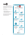
HOW DOES FILTERTRAK WORK?
Simple, One-Time
R
egistration of
System with
FilterTrak!
2
. Change Notice
"Filter Change Due"
Notice Generated by
FilterTrak and
Received
Most Filters Shipped
Same Day.
Filters Changed by
On-site Store or
Service Personnel.
Change Information
Recorded in
FilterTrak.
Choose Upon Set-up to
Auto-Ship or Manually
Place Filter Orders
Filter Change
Acknowledged in
FilterTrak
3. Order Placed
1.Register
4. Filters Shipped
5.Filters Changed
6.Acknowledgement
Authorized Distributors
Available Through
Filtertrak® is an online application that
enables low maintenance service and filter
monitoring of water treatment systems,
ensuring customers get the full performance
of their system.
FilterTrak manages timely, proper filter
replacement which:
• Reduces maintenance
• Improves operating efficiency
• Assures the quality of ice, beverages, and
steam generating systems
For more information about FilterTrak,
please contact one of our foodservice
master distributors or go to:
www.optipurewater.com
®

5
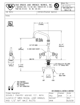
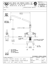
System/ Operating Specification & Connections:
Maximum Pressure: 125 psi/8.6 bar
Operating Temperature: 35° - 100°F (2° - 32°C)
Inlet/Outlet Connections:
1/2” NPT Male Fittings Standard on all Multi-Point Systems
3
/4” NPT Male Fittings are optional
1/2” Push-In-Tube Connections are optional.

6
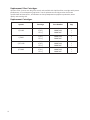
Capacity:
Change filters at gallon rating or at least every 6 months, or when pressure gauge needle enters the
red zone on the outlet gauge while water is flowing through the filter system under normal
operating conditions.
Model
Name
Flowrate Capacity Scale
Inhibitor
Media
Reduction of
gpm lpm gallons Liters
Q
T2+MP
4
.5
1
7
4
5,000
1
70,325
MP*
Particulate Class I , Chlorine, Taste & Odor
QT3MP 6.75 25.5 67,500 255,488
MP*
Particulate Class I , Chlorine, Taste & Odor
QTC2+MP 4.5 17 45,000 170,325
MP*
Chlorine, Taste & Odor, and Cyst
QTC3MP 6.75 25.5 67,500 255,488
MP*
Chlorine, Taste & Odor, and Cyst
MP* - Multi-Point Models (MP) have Scale Inhibitor Outlets that use
IsoNet Scale Inhibitor Media.
Flowrate via Scale Reduction Outlet port is: 2.0 gpm (7.56 lpm)
Capacity via Scale Reduction Outlet port is: 15,000 gallons (56,700 liters)

7
5
"
5
"
5
"
R
1
8
"
R
1
8
"
I
N
L
E
T
>
>
S
C
A
L
E
R
E
D
U
C
T
I
O
N
O
U
T
L
E
T
O
U
T
L
E
T
<
4
3
4
"
26
1
4
"
23
1
4
"
S
HOWN WITH
BALL VALVE ATTACHED
24
1
4
"
Mounting
Dimensions
Dimensional Drawing:

8
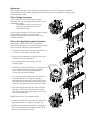
Installation Procedure :
1. Turn off all equipment to be fed by the OptiPure System.
2. Locate water supply cut-off valve and turn off.
3. We recommend that you install a full-flow ball valve of the same size or larger than the
connection fittings on the OptiPure System. Installing a ball valve on the line supplying the
OptiPure System allows the system to be serviced without shutting off the main water
supply. (It will not be necessary to use this valve when replacing filters.)
4. Mount the OptiPure System on a wall stud or suitable mounting material spanning wall
studs.
NOTE: QT3-MP Systems full of water can weigh up to 35 lbs. Use suitable fasteners
when mounting to wall.
5. Run 1/2” Piping / tube or larger feed line from the full-flow ball valve to the top INLET
Connection on the left side of the OptiPure system. For NPT connection: Use 2-3 wraps of
PTFE Thread sealant tape and hold the inlet male fitting on the system with a wrench when
connecting the feed water line.
NOTE: Ensure all piping / tubing being attached to OptiPure System is properly
supported, to ensure proper alignment and that piping / tubing can allow movement
associated with the expansion and contraction of the piping system. Use hangers and
anchors of proper strength to maintain the proportional share weight of the piping /
tubing and contents. Improper piping / tubing support can cause undesired stress and
fatigue on plastic fittings of OptiPure System causing system failure.
NOTE: Do not overtighten connection fittings.
6. Select the appropriate size tubing for the equipment being fed and connect the tubing to the
OUTLET of the OptiPure System. See page 11 for alternate outlet location.
Scale Reduction Outlet on the top right of System, use 2-3 wraps of PTFE Thread sealant tape
to connect supplied 1/2” Ball Valve to 1/2” NPT Male Fitting of the Optipure MP System. Close
1/2” Ball Valve. Connect appropriate size tubing for the equipment requiring Scale Inhibitor
to the Scale Reduction Outlet 1/2” Female NPT Ball Valve on the top right of the system.
Unless Flush Valve Assembly or Flushing Line is installed prior to making connection to the
equipment, DO NOT connect the tubing from OUTLET of OptiPure System to the equipment
at this time, this tubing from the OUTLET can be used to flush the system.
Installation Precautions:
• Do NOT install system on line pressure above 100 psi.
• Do NOT install the system backwards with the feed water line connected to the outlet.
• Do NOT use liquid pipe compounds for fitting connections. USE two to three wraps of
PTFE thread sealant tape.
•
Do NOT allow system to freeze. Turn off water supply to housing and drain housing if
temperature falls below 33°F.
• Do NOT install system in direct sunlight or where system is exposed to harsh chemicals or
may be subjected to being struck by moving equipment, carts, mops or any other item
that may cause damage.
• IF water hammer is evident, install water hammer arrestors before OptiPure unit.

9
I
nstallation Procedure (continued):
7. With OptiPure Multi-Function Valve set in the off position (See Figure 2 on page 10) and Scale
Reduction Outlet ball valve being closed, slowly open the full-flow ball valve at the water
source.
C
heck for leaks from plumbing leading into the OptiPure System.
8. Flushing of system before use.
NOTE: NO ACTIVATION IS REQUIRED FOR THE OPTIPURE SYSTEM TO PERFORM PROPERLY.
FLUSHING IS RECOMMENDED TO ALLOW AIR TO ESCAPE THE SYSTEM AND REMOVE ANY
CARBON FINES PRIOR TO CONNECTING TO EQUIPMENT.
Scale Reduction Outlet does not require flushing.
Three possible flush port connections:
(NOTE: a. and b. allow for convenient flushing after filter replacement.)
a. A Flush Valve Assembly included in the parts pack can be attached to the Multi-Function
Valve port opening. See page 15 for more information. When using this option, connect
the system outlet tubing to the equipment before flushing.
b. A tee (not supplied) can be added on the outlet line from the system. Install a manual
shut-off valve (not supplied) on the branch of the tee. When using this option, connect
outlet tubing from the tee to the equipment before flushing.
c. If no flush valve is installed, use the outlet tubing that is not yet connected to the
equipment for flushing.
Flushing steps:
1. Hold tubing from the chosen flush connection in a bucket or over a sink or drain.
2. Slowly turn the Multi-Function Valve top handle into the Operating Position.
(See Figure 1 on page 10.) Turn Flush Valve Options a. / b. to open positions.
3. Allow water to flush through the OptiPure System for 5 to 10 minutes or until the water
runs clear.
4. Turn Multi-Function Valve to the Off Position. (See Figure 2 on page 10.)
5. If flush connection a. or b. is used, be sure to turn the shut-off valve to the Off position.
If flush connection c. was chosen, connect the outlet tubing to the equipment at this
time. Ensure that the tubing is clean before connecting to the equipment.
9. With tubing connected to equipment. Turn Multi-Function Valve to the Operating Postion
(See Figure 1 on page 10) and open Scale Reduction Outlet ball valve and check for leaks.
10. If no plumbing leaks, turn on equipment and check for normal operation of equipment.
11. Register your system with FilterTrak.

10
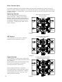
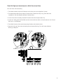
Multi-Function Valve
The OptiPure Manifold System includes a Multi-Function Valve that allows the System to have the
water turned off, or be put into bypass. The white handles on the valve provide a clear indication of
the water flow path in each position. The three points on the tee shape of the handle indicate a path
the flow can take.
Operating Position
This is the position of the handles during
normal operation. Looking at the handle
pointers, you can see that feed water flows
from the INLET port into the filter system and
treated water flows out of the system to the
OUTLET port. The bypass path from inlet to
outlet is blocked.
Off Position
In this position, the inlet water is stopped
before entering the OptiPure System.
Bypass Position
In this position, the INLET water is diverted to
the OUTLET port and all flow to and from the fil-
ters is blocked.
Equipment does not have treated water at this
time, so this should only be used when
issues with filtration are occurring.
Alternate Bypass Position is used when
Outlet connection is switched to right side of
manifold. Note: Non treated water is flowing
thru manifold at this time. See page 11 for
Alternated Outlet Location.
INLET
O
UTLET
Raw
W
ater IN
Treated
Water OUT
Filter
System
Filter System Operating Position
(Service Position)
Water
C
onnections
INLET
OUTLET
OPEN
Raw
Water OFF
Treated
Water OPEN
Filter
System
Incoming Water OFF Position 1
(Primary Off)
Water
Connections
INLET
Raw Water
OUTLET
Raw Water
Raw
Water OFF
Treated
Water OFF
Filter
System
Incoming Water BYPASS Position 1
(Standard Plumbing of Outlet)
Water
Connections
FIGURE 3
FIGURE 2
FIGURE 1

11
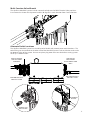
Alternate Outlet Locations
The OptiPure Manifold System has the ability to be flexible with treated water outlet locations. The
outlet fitting can be switched to the other end of the Manifold System if Inlet and Outlet needs to be
on opposite sides of the system. Be sure to replace plug onto alternate side before starting system.
NOTE: QT-3 shown below.
Multi-Function Valve Wrench
The OptiPure Manifold Systems include a wrench to help turn the Multi-Function Valve positions.
Insert wrench as shown to help rotate handles 90 degrees in each direction from Service Position.
REMOVE CLIP
AND FITTING
BOTTOM OUTLETS
FOR FULL FLOW
TOP OUTLET
MULTI-POINT
SCALE REDUCTION
ONLY
INLET IS ALWAYS
TOP LEFT PORT
OPENING!
BOTTOM OUTLETS
FOR FULL FLOW
ALTERNATE
OUTLET

12
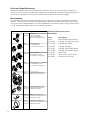
Replacement Filter Cartridges:
OptiPure Filter Systems are designed, tested, and certified with OptiPure filter cartridges with proven
performance, size and operating capacities. Use of replacement cartridges other than those
specified will void warranties, certifications and may compromise equipment protection, water
quality and cartridge life.
Replacement Cartridges:
System Cartridge Part Number Qty.
QT2+MP
S5-Q
CTO-Q
PTS-Q
300-05802
300-05830
300-05805
1
2
1
QT3MP
CTO-Q
PTS-Q
300-05830
300-05805
3
1
QTC2+MP
S5-Q
XTO-Q
PTS-Q
300-05802
300-05840
300-05805
1
2
1
QTC3MP XTO-Q
PTS-Q
300-05840
300-05805
3
1

13
Filter Change Frequency:
Several situations will mandate filter changes.
C
omplete filter sets should be changed when any of
the following apply:
• Six (6) Months have passed since unit
installation or previous filter change.
• Reduced water flow.
If filter change frequency is less than 6 months due to
pressure drop, it may be necessary to add
additional prefiltration or evaluate system sizing
recommendations.
Filter Cartridge Replacement Procedure:
IMPORTANT: Determine whether all equipment
connected to the OptiPure System must be turned off
prior to shutting off water supply from filters.
1. On Multi-Function Valve Turn Upper handle to the
OFF Position. (See figure 2 on page 10)
2. Relieve pressure downline by opening flush valve
or briefly actuating equipment.
3. Turn cartridge to the left 1/4 turn until the
cartridge stops.
4. Pull down on the cartridge until the cartridge clears
the system connection. Discard old cartridge.
NOTE: Some water will drip from Optipure
System during cartridge removal.
5. Line up the upward-arrow on the new cartridge
with the arrow on the side of the cartridge
connection on the Optipure System. NOTE: Some
cartridges do not have arrows. Reference the Key
Feature in the figure when connecting to system.
6. Push cartridge up into head until the base of the
cartridge is next to the base of the filter system.
Turn the cartridge to the right about a 1/4 turn or
until the cartridge stops.
REPEAT Steps 3 thru 6 on additional filters.
7. On Multi-Function Valve Turn Upper Handle to the
Operation Position. (See figure 1 on page 10)
8. Follow flushing procedure used for installation to
flush new cartridges for a recommended 5 to 10
minutes or until water runs clear.
Operation:
With adequate pressure, normal operation of the OptiPure System is completely automatic.
Dependable operation involves only monitoring of outlet pressure, periodic filter changes and
service documentation.
Filter Cartridge
Arrow / Key Feature
STEP 2
S
TEP 3
STEP 1
STEP 4
STEP 5
STEP 6
STEP 7

14
Optional Kit
Flush Valve Assembly
(
1) Flush Valve Assembly
(8ft) - 3/8” (TUBE NOT SHOWN)
Optional Fitting Kit
1/2” Tube Connection
(
2) - Connectors, O-rings, Clips
K
IT #:
170-52912
O
PTIONAL KITS & REPLACEMENT PARTS
KIT #:
5
75-92272
Optional Fitting Kit
3/4 NPT MALE Connection
(2) - Connectors, O-rings, Clips
KIT #:
575-92273
Optional Fitting Kit
1/2 NPT MALE Connection
(2) - Connectors, O-rings, Clips
KIT #:
575-92274
Replacement Assembly / Part
Bypass / Multi-Functional Valve
Part:
575-92274
Replacement Assembly / Part
(1) Plug Assembly with O-ring
(1) Manifold, Head Clip
Parts:
575-92264
575-92225
Replacement Assembly / Part
(1) Port Plug Assembly with O-ring
(1) Manifold, Port Clip
Parts:
575-92265
575-92230
Replacement Assembly / Part
(1) PSI Gauge Assembly with O-ring
(1) Manifold, Port Clip
Parts:
575-92266
575-92230
Pressure Gauge Monitoring:
Periodically monitor the pressure gauge on the OptiPure System. If the needle on the gauge ever
enters the red zone (while the connected equipment is in operation and water is flowing through the
system to the equipment) it may be an indication that the filters have become clogged.
Maintenance:
The only routine maintenance your OptiPure System should ever require is periodic filter cartridge
changes. Filter changes are necessary for optimum performance of your foodservice equipment. If
the system sizing recommendations have been followed the OptiPure System is designed to provide
a six (6) month filter replacement interval on most tap water.
Additional Replacement Parts
(Not Shown):
Part# Description
19782 Multi-Function Valve Wrench
575-92233 O-Ring 0-118 (Body & Fittings)
575-92234 O-Ring 0-021 (Body)
575-92235 O-Ring 0-110 (Port)
575-92239 O-Ring 0-120 (Handle Lower)
575-92240 O-Ring 0-122 (Handle Upper)
575-92251 Cover 4 Up
575-92232 Cover Screw 1/4-.375 Black
520-12031 Valve Ball 1/2 NPT PVC

15
Flush Kit Optional attachment to Multi-Function Valve
To install Flush Valve Assembly:
1. Turn Multi-function Valve to Off Position and relieve pressure to OptiPure System.
2
. To remove White Port Plug on Multi-Function Valve remove Port Clip using small flat head
screwdriver. Pull Port Plug out of Multi-Function Valve.
3. Insert Flush Valve Assembly into Multi-Function Valve Port. Replace Port Clip.
4. Install 3/8” Tubing (NOT INCLUDED) into ball valve and direct other end into bucket or sink. Ensure
ball valve is in off position.
5. Turn Multi-Function Valve to the Operating Position and check for leaks.
6. Open ball valve on Flush Valve Assembly to verify water flushing. Turn ball valve off when
flushing is complete.
PORT CLIP
PORT PLUG

Manufactured by :
OptiPure
101 S. Gary Ave, suite A
Roselle, IL 60172
p: 972.881.9797 e: [email protected]
www.optipurewater.com
-
 1
1
-
 2
2
-
 3
3
-
 4
4
-
 5
5
-
 6
6
-
 7
7
-
 8
8
-
 9
9
-
 10
10
-
 11
11
-
 12
12
-
 13
13
-
 14
14
-
 15
15
-
 16
16


OptiPure QT SERIES Installation, Operation & Maintenance Manual
- Category
- Sanitary ware
- Type
- Installation, Operation & Maintenance Manual
Ask a question and I''ll find the answer in the document
Finding information in a document is now easier with AI
Related papers

Other documents
-
 T & S Brass & Bronze Works B-0270 Datasheet
-
DuPont WFQT130005 User guide
-
 T & S Brass & Bronze Works B-0272 Datasheet
-
 T & S Brass & Bronze Works B-0271 Datasheet
-
A.O. Smith AO-MF Installation guide
-
Watts PWMB10M20 Installation guide
-
3M High Flow Series Replacement Cartridge Kit, Model CARTPAK DP295-CL, 5613818 User manual
-
Watts 7100333 Installation guide
-
3M High Flow Series Scale Feeder Single Manifold Assembly (SF1XX), 6228601 User manual
-
C PURE 790OCLOKITS User manual


