Project: ___________
Item No.: ___________
Quantity: ___________
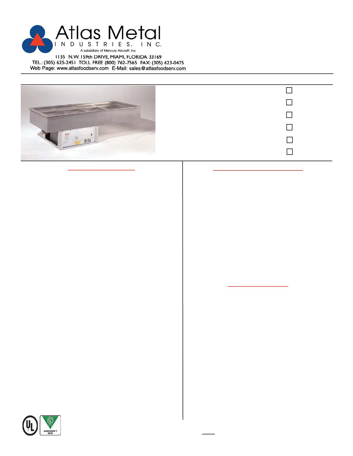
DROP-IN SERVING EQUIPMENT
COLD PAN
(3” Recessed Top)
Refrigerated
with Side Coils
Self-Contained
RM-1
RM-2
RM-3
RM-4
RM-5
RM-6
TOP: Constructed of 18 gauge, type 304 stainless steel, die
stamped with a raised perimeter bead. There shall be a solid
vinyl gasket under the beaded edge to form a seal to the
counter top, thus preventing seepage or marring of the
counter top. Embossed mounting lugs are provided along the
inner surface, 3” down from the top, to hold the pan rails and
a full set of removable separator channels in place.
LINER: The inner liner shall be 18 gauge, type 304 stainless
steel with a 3" recessed top, one piece construction, all
welded, ground and polished to a uniform finish. All corners
are coved with a minimum 1/4" radius. The liner has copper
tubing firmly soldered to the top 3" on all sides. A 3/4 dia.
drain with strainer, 4" PVC nipple, and valve is provided.
INSULATION: The pan is fully insulated with high density
polystyrene, 1" thick on all sides, 2" thick on the bottom and
enclosed with a 22 gauge galvanized steel outer case.
REFRIGERATION SYSTEM: The compressor housing shall
be fabricated from 14 gauge galvanized and bolted to the
base of the unit. A fully self-contained condensing unit is pro-
vided with a hermetically sealed compressor and digital elec-
tronic thermostat/thermometer. The system is fully charged
with CFC free refrigerant and ready to operate.
NOTE: Proper ventilation must be provided in the counter.
ELECTRICAL: The unit will be wired for 15 amps., 120 volt,
single phase operation with an on/off switch and pilot light. A
6' long, 3-wire cord and plug (NEMA 5-15P) will be provided.
Specifications subject to change without notice.
SPECIFICATIONS STANDARD FEATURES
Refrigerated copper tubing, within the 3” recess,
around all sides - meets your toughest health
department standards
Fully insulated for maximum efficiency and energy
savings
Factory applied gasket - makes installation a snap and
seals units to the counter top, thus eliminating
seepage
Accommodates standard 12” X 20” pans with the use
of separator channel(s) and pan rails, or fractional size
pans with the use of optional adapter bars
1-Year Parts & Labor Warranty
NSF Certified; UL Recognized
ACCESSORIES
5YW - 5-Year Compressor Warranty
WFB - Stainless steel perforated false bottom
Stainless Steel adapter bars (pg DI-51-52)
Stainless Steel adapter plates (pg DI-51-52)
CP - Cover Plate with handles, S/S
2060-1 - Condensate Evaporator
RS - Remote on/off switch for counter mounting
* RDVE - Rear Drain Valve Extension
* 220 Volt - 50 Cycle Compressor
* Units with these accessories are not currently UL listed.
RM-4
DI-17


