Page is loading ...

INSTALLATION GUIDE FOR
LDK SOLAR PHOTOVOLTAIC MODULES
Version: April 2011
LDK SOLAR CO. LTD.
1、
、、
、 INTRODUCTION
This guide contains information regarding the installation and safe handling of LDK Solar photovoltaic
module. All instructions should be read and understood before attempting to install. If there are any
questions, please contact LDK Solar Technical Service department for further explanation.
The following document refers to the following crystalline modules manufactured by LDK Solar:
Mono-crystalline:
• LDK-160D-24(s) to LDK-200D-24(s), LDK-200D-20(s) to LDK-250D-20(s).
• LDK-200D-20 to LDK-250D-20.
Poly-crystalline :
• LDK-160P-24(s) to LDK-200P-24(s), LDK-200P-20(s) to LDK-250P-20(s) and LDK-250P-24(s)
to LDK-290P-24(s).
• LDK-200P-20 to LDK-250P-20 and LDK-250P-24 to LDK-290P-24.
1.1 Disclaimer of liability
Because the use of this manual and the conditions or methods of installation, operation, use and
maintenance of photovoltaic (PV) product are beyond LDK Solar’s control, LDK Solar does not accept
responsibility and expressly disclaims liability for loss, damage, or expense arising out of or in any way
connected with such installation, operation, use or maintenance.
No responsibility is assumed by LDK Solar for any infringement of patents or other rights of third
parties, which may result from use of the PV product. No license is granted by implication or otherwise
under any patent or patent rights.
The information in this manual is based on LDK Solar’s knowledge and experience and is believed to
be reliable; but such information including product specification (without limitations) and suggestions
do not constitute a warranty, expresses or implied. LDK Solar reserves the right to change the manual,
the PV product, the specifications, or product information sheets without prior notice.
1.2 Product identification
Each module provides the following information:
Nameplate: describes the product type, rated power, rated current, rated voltage, open circuit voltage,
short circuit current, all as measured under standard test conditions, weight, dimension etc. the
maximum system voltage is shown on the nameplate.
Bar code: each individual module has a unique serial number. There is only one bar code on module. It
is permanently attached to the interior of the module visible when viewing from the front of the module.
This bar code is inserted at the beginning of laminating.
Figure 1. Example of LDK module label
1.3 Quality and Safety Standards
LDK Solar photovoltaic modules meet all the requirements by the following
official Standards in terms of Quality and Safety:
IEC 61215: Design qualification and type approval
IEC 61730-1 and 2: Photovoltaic module safety qualification
UL1703-2002
ULC/ORD-C1703-01
ULand Canadian Standard for safety flat-plate Photovoltaic modules and
panels
ISO 9001:Quality management system for manufacture and sales of
Photovoltaic solar modules

________________________________________________________________________________________________________________________________________
LDK Installation Guide for Photovoltaic Solar Modules – Version: April 2011
All rights strictly reserved reproduction or issue to third parties in any form what ever is not permitted without written authority from the proprietor.
1.4 Limited warranty
Module warranty conditions are described in the LDK Solar document: LDK Solar Limited Warranty for
PV Module.
Ignoring the instructions and considerations described herewith can be a cause by LDK Solar to
invalidate the warranty in case of provable negligence. Please contact to the Technical Support
Service for any question s about warranties.
2、
、、
、 SAFETY
LDK Solar PV modules have passed all required safety tests and certification according to the IEC
61730 with Application Class A, and as Safety Class II according to the IEC 61140. Fire safety has
been rated as Class C, reaching all requirements to be mounted on Class A roofs.
2.1 General Safety
All PV modules should be installed according to all local and national
applicable standards, codes and regulations.
Installation should be performed only by qualified persons. Installers
should assume the risk of all injury that might occur during installation,
including, without limitation, the risk of electric shock.
Check and follow all safety precautions specified for other components of
the system.
Rooftop installations should be placed over fire resistant roofs only.
Do not attempt to disassemble the modules, and do not remove any attached nameplates or
components from the modules.
Do not apply paint or adhesive to module top surface.
Do not use mirrors or other magnifiers to artificially concentrate sunlight on the modules. Do not
expose back sheet foils directly to sunlight.
2.2 Handling Safety
Do not stand or step on module.
Do not drop module or allow objects to fall on module.
To avoid glass breakage, do not place any heavy objects
on the module.
Do not set the module down hard on any surface.
Inappropriate transport and installation may break module.
2.3 Installation Safety
Installing solar photovoltaic systems requires specialized skills and knowledge.
One individual module may generate DC voltages greater than 30 volts when exposed to direct
sunlight. Contact with a DC voltage of 30V or more is potentially hazardous.
Do not disconnect under load.
It is recommended to completely cover the module with an opaque material during installation to
keep electricity from being generated.
Do not wear metallic rings, watchbands, ear, nose, lip rings or other metallic devices while installing
or troubleshooting photovoltaic systems.
Use only insulated tools that are approved for working on electrical installations. Abide with the
safety regulations for all other components used in the system, including wiring and cables,
connectors, charging regulators, inverters, storage batteries and rechargeable batteries, etc.
Use only equipment, connectors, wiring and support frames suitable for a solar electric system.
Always use the same type of module within a particular photovoltaic system.
Do not attempt to repair any part of the PV module.
3、
、、
、INSTALLATION
3.1 Design considerations
LDK Solar PV modules should be installed in a location where they will receive the maximum amount
of sunlight throughout the year. In the Northern Hemisphere modules should face south, while in the
Southern Hemisphere modules should face north. Therefore, modules facing more than 30 degrees
away from true South (or North) could lose approximately from 10% to 30% of their power output.
LDK Solar PV modules connected in series should be installed at same orientation and angle. Different
orientation or angles may cause a loss of power output due to the change in sunlight exposure.
To develop the final distribution of the modules conforming the photovoltaic system, consider to keep
suitable access to allow the maintenance and inspection works.
LDK Solar modules series must be installed in the following conditions:
Operating ambient temperature: -40°C to +85°C
Storage temperature: -40°C to +60°C
Humidity: below 85RH%
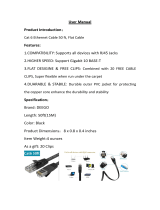
When installing a module on a roof or building, ensure that it is securely fastened and cannot fall as a
result of wind or snow loads and provide adequate ventilation under a module for cooling
(recommended 10cm minimum air space between module and mounting surface).
LDK Solar modules are not allowed to be mounted in mobile applications or in marine environments
with direct contact with salty water, please avoid installing the modules on places directly exposed to
the sea.
Figure 2. Provide adequate ventilation under a module

________________________________________________________________________________________________________________________________________
LDK Installation Guide for Photovoltaic Solar Modules – Version: April 2011
All rights strictly reserved reproduction or issue to third parties in any form what ever is not permitted without written authority from the proprietor.
3.2 Mechanical installation
Use always structures and materials specifically developed and certified for photovoltaic modules
installation.
The minimum distance between two modules for linear thermal expansion of the module frames
should be 5mm, but recommended distance between two solar modules is 20mm to allow wind
circulation to reduce loads and improve module ventilation. The PV module should not be mounted in
such a way that the drain holes of PV module can incur blockage.
The PV modules are suitable for mechanical mounting both in portrait and landscapte orientation. In
choosing the orientation, please keep in mind the internal PV module by-pass diode configuration to
ensure the optimum electrical behaviour from any potential shadings over the modules.
To prevent Electrolysis Corrosion due to the anodized aluminum in the module frame, PVC or stainless
steel washers can be placed between the PV module frame and support structure. Additionally, all
module support structures used to support PV modules at correct tilt angles should be wind and snow
load rated by appropriate local and civil codes prior to installation.
Note: It is not allowed to dismount, drill or modify the frame or any other part of the PV module. This
may cause the loss of warranty. Please contact LDK Technical Service Contact if module mounting
procedure is not clear.
3.2.1 Frame holes mounting
Modules must be securely attached to the mounting structure using four mounting points(14mm*9mm).
Use M8 stainless steel hardware, spring washers and flat washers with a torque of approximately 8
Newton-meters for normal installation. Refer to the drawings on the Annex 1 to get more information
about the use of mounting holes and load resistance of all module types.
Figure 3. Frame holes mounting
3.2.2 Pressure clips mounting
The modules should be fixed to the structure by pressure clips on the large side or short side of the
frame according to instructions on Annex 1. The clips must be mounted at the position of the mounitng
hole, with a 10% of total length tolerance to the edge of the module. Note that always both sides
should be mounted in a simetric position respect to the center. Refer to the drawings on the Annex 1.
The clips must only fix the modules by the contact with the frame. Do not allow contact between clip
and glass.
Do not mount the modules by pressure clips out of the specified area. Module mechanical resistance
could be affected.
Figure 4. Clips mounting
3.2.3 Insertion systems
Insertion systems on the short sides of the module are allowed with a limitation on the load resistance
of 2400 Pa. Insertion systems on the large side of the module are not affected by any limitatioin and
are allowed with maximum of 5400 Pa for snow load. See Annex 1 for more information.
3.2.3 Module load resistance
Wind Load: 2400 Pa
Snow Load: 5400 Pa
Wind speed: 130 Km/h
Note that information above provided could vary according to the mounting system and configuration
as described on the Annex 1.
3.3 Electrical installation
The DC electrical energy generated by photovoltaic systems may be converted to AC and connected
to a utility grid system. As local utilities’ policies on connecting renewable energy systems to their grids
vary from region to region, consult a qualified system designer or integrator to design such a system.
Permits are normally required for installing such a system and the utility must formally approve and
inspect such a system before it can be accepted.
Use only insulated tools that are approved for working on electrical installations. Abide with the safety
regulations for all other components used in the system, including wiring and cables, connectors,
charging regulators, inverters, storage batteries and rechargeable batteries, etc.
The electrical characteristics are within ±5 percent of the indicated values of Isc and Voc under

________________________________________________________________________________________________________________________________________
LDK Installation Guide for Photovoltaic Solar Modules – Version: April 2011
All rights strictly reserved reproduction or issue to third parties in any form what ever is not permitted without written authority from the proprietor.
standard test conditions (irradiance of 100mW/cm2, AM 1.5 spectrums, and a cell temperature of 25°C
(77°F)) and tolerance of the Pmax is ±3%.
3.3.1 General considerations
Several modules are connected in series and then in parallel to form a PV array, especially for
application with a high operation voltage. If modules are connected in series, the total voltage is equal
to the sum of individual voltages. Do not use different type of modules in the same circuit.
Modules are fitted with pre-assembled cable leads and safe plug & socket connectors to use for
system electrical connections; these cable leads and connectors must not be removed or cut off
Consult rated local wiring regulations to determine system wire size, type, and temperature for your
installation.
3.3.2 System Grounding
All module frames and mounting racks must be properly grounded. The grounding wire must be
properly fastened to the module frame to assure good electrical contact. Use the recommended
type, or an equivalent, connector for this wire.
If the support structure is made of metal, the surface of the structure must be electroplated and
have excellent conductivity.
Proper grounding is achieved by connecting the module frame(s) and structural members
contiguously using a suitable grounding conductor
The grounding conductor must then make a connection to earth using a suitable earth ground
electrode. We recommend the lay-in lug when grounding. The rack must also be grounded unless
it is mechanically connected by nuts and bolts to the grounded PV modules.
3.3.3 Bypass diode and blocking diode
Partial shading of an individual module can cause a reverse voltage across the shaded PV module; the
current is then forced through the shaded area by the other modules. When a bypass diode is wired in
parallel with the series string, the forced current will flow through the diode and bypass the shaded PV
module, thereby minimizing module heating and array current losses. LDK Solar Photovoltaic modules
are fitted with internal bypass diodes within the junction box to reduce the effects of partial shadings.
4、
、、
、 Commission and maintenace
Test all electrical and electronic components of the system before using it. Follow the instructions in
the guides supplied with the components and equipment. Commission and Maintenance works must
be performed by specialized and properly formed personnel.
Check the open-circuit voltage of every series module by a digital multimeter. The measured values
should correspond to the sum of the open-circuit voltage of the individual module. You will find the
rated voltage in the technical specifications of the type of the module used. If the measured value
is significantly lower than the expected value, please proceed as described under
“Troubleshooting an excessively low voltage”.
Check the short-circuit current of every series circuit. It can be measured directly by a digital
multimeter connected in the two terminals of series circuit or module, or with any load such as PV
illumination to make a rough measurement. Attention, the rated scale of the ammeter or the rated
current of load should more than 1.25 times of the rated short-circuit current of series module. You
will find the rated current in the technical specifications of the type of module used. The measured
value can vary significantly, depending on weather conditions, the time of day and shading of the
module.
4.1 Troubleshooting low voltages
Identify the commonly low voltage and excessively low voltage. Commonly the low voltage mentioned
here is the decrease of open-circuit voltage of the module, which is caused by the temperature rising of
solar cells or lower irradiance. Excessively low voltage is typically caused by improper connections at
the terminals or defective bypass diodes. Please, contact the LDK Solar Technical Service if the
problem could not be resolved.
4.2 Maintenance
LDK Solar recommends the following maintenance in order to ensure optimum performance of the
module:
Under most weather conditions, normal rainfall is sufficient to keep the PV module glass surface
clean. Clean the glass surface of the module as necessary and consider that lower inclination
requires more cleaning frequency.
Always use water and a soft sponge or cloth for cleaning. A mild, non-abrasive cleaning agent can
be used to remove stubborn dirt.
Check the electrical and mechanical connections every six months to verify that they are clean,
secure and undamaged
If any problem arises, have them investigated by a competent specialist.
Attention, observe the maintenance instructions for all components used in the system, such as
support frames, charging regulators, inverters, batteries etc.
5、
、、
、 Module end-of-life
LDK Solar is a member of the PV CYCLE Association, European association for voluntary take-back
and recycling of photovoltaic modules.
The LDK membership guarantees that after the life span of the installation, all modules will be
collected and recycled by a specialized organization which ensures that all PV process is under
environmental care. All the services are according to European Commission and free of charge for
final users (except incidences during installation).
Please visit PV Cycle web site for further information:
http://www.pvcycle.org/

________________________________________________________________________________________________________________________________________
LDK Installation Guide for Photovoltaic Solar Modules – Version: April 2011
All rights strictly reserved reproduction or issue to third parties in any form what ever is not permitted without written authority from the proprietor.
6、
、、
、 Module specifications
LDK
160/200
D-24 (s)
LDK
160/200
P-24 (s)
LDK
200/250
D-20
LDK
200/250
D-20 (s)
LDK
200/250
P-20
LDK
200/250
P-20 (s)
LDK
250/290
P-24
LDK
250/290
P-24 (s)
A 1580 1580 1642 1630 1642 1630 1958 1946
B 808 808 994 976 994 976 994 976
C 390 390 421 415 421 415 579 573
D 140 140 171 165 171 165 329 323
E 40 40 40 40 40 40 50 50
F 30 30 30 30 30 30 40 40
Cable 950 950 1000 1000 1000 1000 1200 1200
Weight (kg) 15,6 15,6 20 19 20 19 30,5 27,3
Cell type
Mono
125
Multi
125
Mono
156
Mono
156
Multi
156
Multi
156
Multi
156
Multi
156
Num of
Cells
72 72 60 60 60 60 72 72
Connector MC4
Max fuse
rating
20 A
Note: All dimension values are in mm
7、
、、
、 Technical Service Contact
LDK Solar Hi-Tech (Nanchang) Co., Ltd
Add: No. 999 Torch Boulevard, Nanchang, Jiangxi, PRC
Post code: 330096
Tel: +86 791 8105313
Fax: +86 791 8108260
Email: Service@ldksolar.com
Website: www.ldksolar.com

________________________________________________________________________________________________________________________________________
LDK Installation Guide for Photovoltaic Solar Modules – Version: April 2011
All rights strictly reserved reproduction or issue to third parties in any form what ever is not permitted without written authority from the proprietor.
Annex 1: Module installation & load guide
System 1: Installation with mounting holes
All module types
5400Pa
Normal Installation
System 2: Installation with pressure Clips
A – Clips System on large side:
B – Clips System on short side:
All module types
5400Pa
Installation according to drawing specification
All module types
2400Pa
Pressure clips on short side
All module types
Not allowed for 5400 Pa
System 3: Insertion Systems
A – Insertion System on large side:
B – Insertion System on short side:
All module types
5400Pa
Insertion System on large side
All module types
2400Pa
Insertion System on short side
All module types
Not allowed for 5400 Pa
/