Motherboard
M4A89GTD
PRO Series
M4A89GTD PRO/USB3
M4A89GTD PRO

ii
E5471
First Edition (V1)
April 2010
Copyright © 2010 ASUSTeK COMPUTER INC. All Rights Reserved.
No part of this manual, including the products and software described in it, may be reproduced,
transmitted, transcribed, stored in a retrieval system, or translated into any language in any form or by any
means, except documentation kept by the purchaser for backup purposes, without the express written
permission of ASUSTeK COMPUTER INC. (“ASUS”).
product is defaced or missing.
ASUS PROVIDES THIS MANUAL “AS IS” WITHOUT WARRANTY OF ANY KIND, EITHER EXPRESS
OR IMPLIED, INCLUDING BUT NOT LIMITED TO THE IMPLIED WARRANTIES OR CONDITIONS OF
MERCHANTABILITY OR FITNESS FOR A PARTICULAR PURPOSE. IN NO EVENT SHALL ASUS, ITS
DIRECTORS, OFFICERS, EMPLOYEES OR AGENTS BE LIABLE FOR ANY INDIRECT, SPECIAL,
INCIDENTAL, OR CONSEQUENTIAL DAMAGES (INCLUDING DAMAGES FOR LOSS OF PROFITS,
LOSS OF BUSINESS, LOSS OF USE OR DATA, INTERRUPTION OF BUSINESS AND THE LIKE),
EVEN IF ASUS HAS BEEN ADVISED OF THE POSSIBILITY OF SUCH DAMAGES ARISING FROM ANY
DEFECT OR ERROR IN THIS MANUAL OR PRODUCT.
SPECIFICATIONS AND INFORMATION CONTAINED IN THIS MANUAL ARE FURNISHED FOR
INFORMATIONAL USE ONLY, AND ARE SUBJECT TO CHANGE AT ANY TIME WITHOUT NOTICE,
AND SHOULD NOT BE CONSTRUED AS A COMMITMENT BY ASUS. ASUS ASSUMES NO
RESPONSIBILITY OR LIABILITY FOR ANY ERRORS OR INACCURACIES THAT MAY APPEAR IN THIS
MANUAL, INCLUDING THE PRODUCTS AND SOFTWARE DESCRIBED IN IT.
Products and corporate names appearing in this manual may or may not be registered trademarks or
Offer to Provide Source Code of Certain Software
This product may contain copyrighted software that is licensed under the General Public License (“GPL”)
and under the Lesser General Public License Version (“LGPL”). The GPL and LGPL licensed code in this
product is distributed without any warranty. Copies of these licenses are included in this product.
and/or the complete corresponding source code of the LGPL Software (with the complete machine-
readable “work that uses the Library”) for a period of three years after our last shipment of the product
including the GPL Software and/or LGPL Software, which will be no earlier than December 1, 2011, either
(1) for free by downloading it from http://support.asus.com/download
or
(2) for the cost of reproduction and shipment, which is dependent on the preferred carrier and the location
where you want to have it shipped to, by sending a request to:
ASUSTeK Computer Inc.
Legal Compliance Dept.
15 Li Te Rd.,
Beitou, Taipei 112
Taiwan
In your request please provide the name, model number and version, as stated in the About Box of the
product for which you wish to obtain the corresponding source code and your contact details so that we
can coordinate the terms and cost of shipment with you.
The source code will be distributed WITHOUT ANY WARRANTY and licensed under the same license as
the corresponding binary/object code.
This offer is valid to anyone in receipt of this information.
ASUSTeK is eager to duly provide complete source code as required under various Free Open Source
Software licenses. If however you encounter any problems in obtaining the full corresponding source code
[email protected], stating the
product and describing the problem (please do NOT send large attachments such as source code archives
etc to this email address).

iii
Contents
Contents ...................................................................................................................... iii
Notices ...................................................................................................................... vii
Safety information .................................................................................................... viii
About this guide ......................................................................................................... ix
M4A89GTD PRO Series specications summary ................................................... xi
Chapter 1: Product introduction
1.1 Welcome! .................................................................................................... 1-1
1.2 Package contents.......................................................................................1-1
1.3 Special features..........................................................................................1-2
1.3.1 Product highlights........................................................................1-2
1.3.2 ASUS Xtreme Design—Hybrid Processor .................................. 1-2
1.3.3 ASUS Xtreme Design—Hybrid Switches .................................... 1-3
1.3.4 ASUS Xtreme Design—Hybrid OS ............................................. 1-3
1.3.5 ASUS unique features.................................................................1-3
Chapter 2: Hardware information
2.1 Before you proceed ................................................................................... 2-1
2.2 Motherboard overview ............................................................................... 2-2
2.2.1 Motherboard layout ..................................................................... 2-2
2.2.2 Layout contents ........................................................................... 2-3
2.2.3 Placement direction.....................................................................2-4
2.2.4 Screw holes.................................................................................2-4
2.3 Central Processing Unit (CPU) ................................................................. 2-5
2.3.1 Installing the CPU ....................................................................... 2-5
2.3.2 Installing the CPU heatsink and fan ............................................ 2-7
2.4 System memory ....................................................................................... 2-10
2.4.1 Overview ................................................................................... 2-10
.............................................................. 2-11
2.4.3 Installing a DIMM ...................................................................... 2-16
2.4.4 Removing a DIMM .................................................................... 2-16
2.5 Expansion slots........................................................................................2-17
2.5.1 Installing an expansion card......................................................2-17
................................................. 2-17
2.5.3 Interrupt assignments................................................................2-18
2.5.4 PCI slots .................................................................................... 2-19
2.5.5 PCI Express 2.0 x4 / x1 slots .................................................... 2-19
2.5.6 PCI Express 2.0 x16 slots ......................................................... 2-19
2.6 Jumper ...................................................................................................... 2-21
2.7 Onboard switches .................................................................................... 2-22

iv
Contents
2.8 Connectors ............................................................................................... 2-25
2.8.1 Rear panel connectors .............................................................. 2-25
2.8.2 Audio I/O connections ............................................................... 2-28
2.8.3 Internal connectors....................................................................2-30
2.8.4. ASUS Q-Connector (system panel) .......................................... 2-38
2.9 Onboard LEDs .......................................................................................... 2-39
2.10 Starting up for the rst time .................................................................... 2-41
2.11 Turning off the computer .........................................................................2-41
Chapter 3: BIOS setup
3.1 Knowing BIOS ............................................................................................ 3-1
3.2 Updating BIOS ............................................................................................ 3-1
3.2.1 ASUS Update utility.....................................................................3-2
3.2.2 ASUS EZ Flash 2 utility ............................................................... 3-4
3.2.3 ASUS CrashFree BIOS 3 utility................................................... 3-5
3.2.4 ASUS BIOS Updater ................................................................... 3-6
3.3 BIOS setup program .................................................................................. 3-9
3.3.1 BIOS menu screen ...................................................................... 3-9
3.3.2 Menu bar ..................................................................................... 3-9
3.3.3 Navigation keys ......................................................................... 3-10
3.3.4 Menu items................................................................................3-10
3.3.5 Submenu items ......................................................................... 3-10
................................................................... 3-10
3.3.7 Pop-up window..........................................................................3-10
3.3.8 Scroll bar ................................................................................... 3-10
3.3.9 General help..............................................................................3-10
3.4 Main menu ................................................................................................ 3-11
3.4.1 SATA 1–6 .................................................................................. 3-11
............................................................... 3-13
3.4.3 System Information ................................................................... 3-14
3.5 Ai Tweaker menu ......................................................................................3-15
3.5.1 CPU Level UP ........................................................................... 3-15
3.5.2 OC Tuner Utility ......................................................................... 3-16
3.5.3 Ai Overclock Tuner .................................................................... 3-16
3.5.4 CPU Ratio ................................................................................. 3-17
3.5.5 DRAM Frequency...................................................................... 3-17
3.5.6 CPU/NB Frequency................................................................... 3-17
3.5.7 HT Link Speed .......................................................................... 3-17
...................................................... 3-17

v
..................................................... 3-18
3.5.10 CPU & NB Voltage Mode .......................................................... 3-19
3.5.11 CPU VDDA Voltage ................................................................... 3-19
3.5.12 DRAM Voltage........................................................................... 3-19
3.5.13 CPU Load-Line Calibration ....................................................... 3-20
3.5.14 CPU/NB Load-Line Calibration ................................................. 3-20
3.5.15 CPU Spread Spectrum.............................................................. 3-20
3.5.16 PCIE Spread Spectrum ............................................................. 3-20
3.5.17 HT Voltage ................................................................................3-20
3.5.18 NB Voltage ................................................................................ 3-20
3.5.19 NB 1.8V Voltage ........................................................................ 3-20
3.5.20 SB Voltage ................................................................................ 3-20
3.5.21 SidePort Memory Voltage ......................................................... 3-20
3.5.22 Internal Graphics Mode ............................................................. 3-21
3.5.23 GFX Engine Clock Override ...................................................... 3-21
3.6 Advanced menu ....................................................................................... 3-22
.................................................................... 3-22
3.6.2 Chipset ...................................................................................... 3-23
................................................ 3-26
.................................................................... 3-27
3.6.5 PCIPnP ..................................................................................... 3-28
3.7 Power menu .............................................................................................. 3-29
3.7.1 Suspend Mode .......................................................................... 3-29
3.7.2 Repost Video on S3 Resume .................................................... 3-29
3.7.3 ACPI 2.0 Support ...................................................................... 3-29
3.7.4 ACPI APIC Support ................................................................... 3-29
.................................................................... 3-30
3.7.6 Hardware Monitor...................................................................... 3-31
3.8 Boot menu ................................................................................................ 3-33
3.8.1 Boot Device Priority................................................................... 3-33
...................................................... 3-34
3.8.3 Security ..................................................................................... 3-35
3.9 Tools menu ............................................................................................... 3-37
3.9.1 ASUS EZ Flash 2 ...................................................................... 3-37
3.9.2 Express Gate ............................................................................ 3-37
..................................................................... 3-38
3.9.4 AI NET 2 .................................................................................... 3-39
3.9.5 POST State LEDs ..................................................................... 3-39
3.10 Exit menu .................................................................................................. 3-40
Contents

vi
Chapter 4: Software support
4.1 Installing an operating system ................................................................. 4-1
4.2 Support DVD information .......................................................................... 4-1
4.2.1 Running the support DVD ........................................................... 4-1
4.2.2 Obtaining the software manuals.................................................. 4-2
4.3 Software information ................................................................................. 4-3
4.3.1 ASUS PC Probe II ....................................................................... 4-3
4.3.2 ASUS AI Suite ............................................................................. 4-4
4.3.3 ASUS Fan Xpert..........................................................................4-5
4.3.4 ASUS EPU .................................................................................. 4-6
4.3.5 ASUS Express Gate....................................................................4-7
.................................................................... 4-8
4.3.7 ASUS GPU Boost ....................................................................... 4-9
4.4 ASUS Unique Overclocking Utility—TurboV EVO ................................. 4-10
4.4.1 Using ASUS TurboV .................................................................. 4-10
4.4.2 Using Turbo Unlocker................................................................ 4-11
4.4.3 Using ASUS TurboV Auto Tuning Mode .................................... 4-12
4.4.4 Using CPU Level UP ................................................................. 4-13
4.4.5 Using ASUS Turbo Key ............................................................. 4-13
4.5 RAID congurations ................................................................................ 4-14
........................................................................ 4-14
4.5.2 Installing Serial ATA hard disks ................................................. 4-15
4.5.3 Setting the RAID item in BIOS .................................................. 4-15
4.5.4 AMD® Option ROM Utility .......................................................... 4-16
4.6 Creating a RAID driver disk.....................................................................4-19
4.6.1 Creating a RAID driver disk without entering the OS ................ 4-19
4.6.2 Creating a RAID driver disk in Windows® .................................. 4-19
4.6.3 Installing the RAID driver during Windows® OS installation ...... 4-19
................................................... 4-20
Chapter 5: ATI® CrossFireX™ technology support
5.1 ATI® CrossFireX™ technology .................................................................. 5-1
5.1.1 Requirements .............................................................................. 5-1
5.1.2 Before you begin ......................................................................... 5-1
5.1.3 Installing two CrossFireX™ graphics cards ................................ 5-2
5.1.4 Installing the device drivers ......................................................... 5-3
5.1.5 Enabling the ATI® CrossFireX™ technology ...............................5-3
5.2 ATI® Hybrid CrossFireX™ technology ...................................................... 5-4
5.2.1 System requirements .................................................................. 5-4
5.2.2 Before you proceed ..................................................................... 5-4
5.2.3 Installing AMD Chipset Driver ..................................................... 5-4
5.2.4 Using the ATI® CATALYST® Control Center ................................ 5-5
Contents
vii
Notices
Federal Communications Commission Statement
This device complies with Part 15 of the FCC Rules. Operation is subject to the following two
conditions:
• This device may not cause harmful interference, and
• This device must accept any interference received including interference that may cause
undesired operation.
This equipment has been tested and found to comply with the limits for a Class B digital
device, pursuant to Part 15 of the FCC Rules. These limits are designed to provide
reasonable protection against harmful interference in a residential installation. This
equipment generates, uses and can radiate radio frequency energy and, if not installed
and used in accordance with manufacturer’s instructions, may cause harmful interference
to radio communications. However, there is no guarantee that interference will not occur
in a particular installation. If this equipment does cause harmful interference to radio or
television reception, which can be determined by turning the equipment off and on, the user
is encouraged to try to correct the interference by one or more of the following measures:
•
Reorient or relocate the receiving antenna.
•
Increase the separation between the equipment and receiver.
•
Connect the equipment to an outlet on a circuit different from that to which the receiver is
connected.
•
Consult the dealer or an experienced radio/TV technician for help.
Canadian Department of Communications Statement
This digital apparatus does not exceed the Class B limits for radio noise emissions from
digital apparatus set out in the Radio Interference Regulations of the Canadian Department
of Communications.
This class B digital apparatus complies with Canadian ICES-003.
The use of shielded cables for connection of the monitor to the graphics card is required
expressly approved by the party responsible for compliance could void the user’s authority
to operate this equipment.
REACH
Complying with the REACH (Registration, Evaluation, Authorisation, and Restriction of
Chemicals) regulatory framework, we published the chemical substances in our products at
ASUS REACH website at http://green.asus.com/english/REACH.htm.
DO NOT throw the motherboard in municipal waste. This product has been designed to
enable proper reuse of parts and recycling. This symbol of the crossed out wheeled bin
indicates that the product (electrical and electronic equipment) should not be placed in
municipal waste. Check local regulations for disposal of electronic products.
DO NOT throw the mercury-containing button cell battery in municipal waste. This symbol
of the crossed out wheeled bin indicates that the battery should not be placed in municipal
waste.

viii
Safety information
Electrical safety
before relocating the system.
• When adding or removing devices to or from the system, ensure that the power cables
for the devices are unplugged before the signal cables are connected. If possible,
disconnect all power cables from the existing system before you add a device.
• Before connecting or removing signal cables from the motherboard, ensure that all
power cables are unplugged.
• Seek professional assistance before using an adapter or extension cord. These devices
could interrupt the grounding circuit.
• Ensure that your power supply is set to the correct voltage in your area. If you are not sure
about the voltage of the electrical outlet you are using, contact your local power company.
technician or your retailer.
Operation safety
• Before installing the motherboard and adding devices on it, carefully read all the manuals
that came with the package.
• Before using the product, ensure all cables are correctly connected and the power
cables are not damaged. If you detect any damage, contact your dealer immediately.
• To avoid short circuits, keep paper clips, screws, and staples away from connectors,
slots, sockets and circuitry.
• Avoid dust, humidity, and temperature extremes. Do not place the product in any area
where it may become wet.
• Place the product on a stable surface.
technician or your retailer.

ix
About this guide
How this guide is organized
This guide contains the following parts:
• Chapter 1: Product introduction
This chapter describes the features of the motherboard and the new technology it
supports.
• Chapter 2: Hardware information
This chapter lists the hardware setup procedures that you have to perform when
installing system components. It includes description of the switches, jumpers, and
connectors on the motherboard.
• Chapter 3: BIOS setup
This chapter tells how to change system settings through the BIOS Setup menus.
Detailed descriptions of the BIOS parameters are also provided.
• Chapter 4: Software support
This chapter describes the contents of the support DVD that comes with the
motherboard package and the software.
• Chapter 5: ATI® CrossFireX™ technology support
This chapter describes the ATI® CrossFireX™ feature and shows the graphics card
installation procedures.
Where to nd more information
Refer to the following sources for additional information and for product and software updates.
1. ASUS websites
The ASUS website provides updated information on ASUS hardware and software
products. Refer to the ASUS contact information.
2. Optional documentation
that may have been added by your dealer. These documents are not part of the
standard package.

x
Conventions used in this guide
To ensure that you perform certain tasks properly, take note of the following symbols used
throughout this manual.
Typography
Bold text Indicates a menu or an item to select.
Italic
<Key> Keys enclosed in the less-than and greater-than sign means
that you must press the enclosed key.that you must press the enclosed key.
Example: <Enter> means that you must press the Enter or
Return key.Return key.
<Key1> + <Key2> + <Key3> If you must press two or more keys simultaneously, the key
names are linked with a plus sign (+).
Example: <Ctrl> + <Alt> + <Del>
DANGER/WARNING: Information to prevent injury to yourself when trying to
complete a task.
CAUTION: Information to prevent damage to the components when trying to
complete a task.
IMPORTANT: Instructions that you MUST follow to complete a task.
NOTE: Tips and additional information to help you complete a task.

xi
M4A89GTD PRO Series specications summary
(continued on the next page)
CPU AMD®
Series Processors
AMD® 140W CPU Support
AMD® Cool ‘n’ Quiet™ Technology Technology
Supports 45nm CPU
Chipset AMD® 890GX / SB850
System bus
Memory
ECC / non-ECC, un-buffered memory
Dual channel memory architecture
* Due to the CPU spec., AMD AM3 100 and 200 series CPUs
With ASUS design, this
** When you install a total memory of 4 GB capacity or more,
Windows®
than 3 GB. We recommend using a maximum of 3 GB system
memory if you are using a Windows® 32-bit OS.
*** Refer to www.asus.com or this user manual for the Memory
Expansion slots 2 x PCI Express 2.0 x16 slots, support ATI, support ATI® CrossFireX™
Technology (@ dual x8 speed)(@ dual x8 speed)
1 x PCI Express 2.0 x4 slot
1 x PCI Express 2.0 x1 slot
2 x PCI slots
VGA Output Integrated ATI® Radeon™ HD 4290 GPU
Multi-VGA output support: HDMI, DVI-D, and RGB ports
Supports HDMI with max. resolution 1920 x 1200 (1080P)
Supports H.264, VC-1, MPEG-2, DirectX 10.1 and OpenGL 2.0
Supports Shader Model 4.1, Universal Video Decoder (UVD) 2.0
128 MB DDR3 1333 sideport memory support
Hybrid CrossFireX support
Storage AMD® SB850 chipset
- 6 x SATA 6.0 Gb/s ports with RAID 0, 1, 5, and 10 support
JMicron® JMB361 PATA and SATA controller
- 1 x Power eSATA 3.0 Gb/s port
- 1 x Ultra DMA 133/100 for up to 2 PATA devices
LAN Realtek® 8111E Gigabit LAN controller featuring AI NET2
Audio
- DTS Surround Sensation UltraPC
- Supports Jack-Detection, Multi-Streaming, and
Front Panel Jack-Retasking
- Optical S/PDIF Out port at back I/O
- ASUS Noise Filter

xii
(continued on the next page)
M4A89GTD PRO Series specications summary
USB M4A89GTD PRO/USB3 model
- 2 x USB 3.0 ports (blue, at back panel)
- 12 x USB 2.0 ports (8 ports at midboard, 4 ports at back panel)
M4A89GTD PRO model
- 14 x USB 2.0 ports (8 ports at midboard, 6 ports at back panel)
IEEE 1394 VIA® VT6308P controller supports 2 x IEEE 1394a ports
(one at midboard, one at back panel)
ASUS unique features ASUS Xtreme Design
ASUS Hybrid Processor – TurboV EVO
- TurboV, Turbo Unlocker, Auto Tuning, CPU Level UP
and GPU Boost
ASUS Hybrid OS – Express Gate
ASUS Hybrid Switches
- Turbo Key II
- Core Unlocker
ASUS Power Solutions
- 8+2 Phase Power Design
- ASUS EPU
ASUS Exclusive Features
- MemOK!
ASUS Quiet Thermal Solutions
- ASUS Fanless Design: Heat pipe solution
- ASUS Fan Xpert
ASUS EZ DIY
- ASUS Q-Design
- ASUS CrashFree BIOS 3
- ASUS EZ Flash 2
- ASUS MyLogo 2™
- Multi-language BIOS
ASUS exclusive
overclocking features
Precision Tweaker 3
- vCore: Adjustable CPU voltage at 0.003125V increment
- vDDNB: Adjustable CPU NB voltage at 0.003125V increment
- vCPU PLL: Adjustable CPU PLL voltage at 0.00625V
increment
- vHT Bus: Adjustable PCH voltage at 0.00625V increment
- vDRAM Bus: Adjustable DRAM voltage at 0.00625V
increment
- vChipset: Adjustable Chipset voltage at 0.00625V increment
SFS (Stepless Frequency Selection)
Overclocking protection
- ASUS C.P.R. (CPU Parameter Recall)
xiii
*Specications are subject to change without notice.
M4A89GTD PRO Series specications summary
Back panel I/O ports 1 x PS/2 keyboard port (purple)
1 x HDMI Out port
1 x DVI-D Out port
1 x D-Sub Out port
1 x Optical S/PDIF Out port
1 x Power eSATA port
1 x IEEE 1394a port
1 x LAN (RJ-45) port
2 x USB 3.0/2.0 ports (blue), and 4 x USB 2.0/1.1 ports (M4A89GTD
PRO/USB3 model)
6 x USB 2.0/1.1 ports (M4A89GTD PRO model)
8-channel Audio I/O ports
Internal I/O connectors 4 x USB connectors support additional 8 USB ports
1 x IDE connector
6 x SATA 6.0 Gb/s connectors
1 x CPU Fan connector
2 x Chassis Fan connectors (1 x 4-pin, 1 x 3-pin)
1 x Power Fan connector
1 x IEEE1394a connector
1 x S/PDIF Out header
1 x Core Unlocker switch
1 x Turbo Key II switch
1 x MemOK! button
Front panel audio connector
1 x COM connector
24-pin ATX Power connector
8-pin EATX 12V Power connector
System Panel
BIOS features 16 Mb Flash ROM, SPI, AMI BIOS, PnP, DMI 2.0, WfM 2.0,
SM BIOS 2.5, ACPI 2.0a, Multi-language BIOS,
ASUS EZ Flash 2, ASUS CrashFree BIOS 3
Manageability WfM 2.0, DMI 2.0, WOL by PME, WOR by PME, PXE
Support DVD contents Drivers
ASUS Utilities
ASUS Update
Anti-virus software (OEM version)
Form factor ATX form factor: 12 in. x 9.6 in. (30.5 cm x 24.4 cm)

xiv
ASUS M4A89GTD PRO Series 1-1
Chapter 1
Chapter 1: Product introduction
Chapter 1
1.1 Welcome!
Thank you for buying an ASUS® M4A89GTD PRO Series motherboard!
The motherboard delivers a host of new features and latest technologies, making it another
standout in the long line of ASUS quality motherboards!
Before you start installing the motherboard, and hardware devices on it, check the items in
your package with the list below.
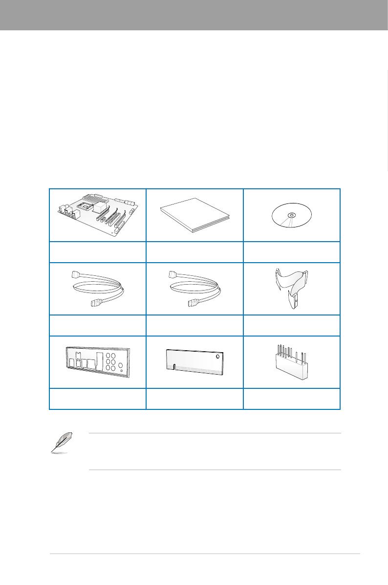
1.2 Package contents
Check your motherboard package for the following items.
• If any of the above items is damaged or missing, contact your retailer.
vary with different models.
User Manual
ASUS M4A89GTD PRO Series
motherboard User guide Support DVD
2 x Serial ATA 6.0 Gb/s cables
with 6.0 Gb/s label 2 x Serial ATA 3.0 Gb/s cables 1 x Ultra DMA 133/
100/66 cable
1 x ASUS Q-Shield 1 x VGA switch card 1 x 2-in-1 ASUS Q-Connector kit

1-2 Chapter 1: Product Introduction
Chapter 1
1.3 Special features
1.3.1 Product highlights
AMD® Phenom™ II / Athlon™ II / Sempron™ 100 Series Processors (socket AM3)
This motherboard supports AMD® AM3 multi-core processors with unique L3 cache and
delivers better overclocking capabilities with less power consumption. It features
dual-channel DDR3 1333 memory support and accelerates data transfer rate up to 5200MT/s
via HyperTransport™ 3.0 based system bus. This motherboard also supports AMD® CPUs in
the new 45nm manufacturing process.
AMD® 890GX Chipset
AMD® 890GX Chipset is designed to support up to 5200MT/s HyperTransport™ 3.0 (HT 3.0)
®’s latest AM3
and multi-core CPUs to provide excellent system performance and overclocking capabilities.
Dual-Channel DDR3 2000(O.C.) / 1333 / 1066 support
The motherboard supports DDR3 memory that features data transfer rates of 2000(O.C.) /
multimedia, and Internet applications. The dual-channel DDR3 architecture enlarges the
bandwidth of your system memory to boost system performance. Refer to page 2-10 for details.
ATI® CrossFireX™ Technology
ATI’s CrossFireX™ boosts image quality along with rendering speed, eliminating the
need to scale down screen resolution to get high quality images. CrossFireX™ allows
real-time 3D-rendered previews within ATI Catalyst™ Control Center.
AMD® SB850 Chipset
The AMD® SB850 Southbridge natively supports the next generation SATA 6.0 Gb/s data
transfer rate and PCI Express 2.0 interface.
True USB 3.0 Support (M4A89GTD PRO/USB3 model only)
Experience ultra-fast data transfers at 4.8 Gb/s with USB 3.0–the latest connectivity standard.
Built to connect easily with next-generation components and peripherals, USB 3.0 transfers
data 10X faster and is also backward compatible with USB 2.0 components.
1.3.2 ASUS Xtreme Design—Hybrid Processor*
TurboV EVO
to beginners. Auto tuning intelligently pushes the system to the fastest clock speeds while
more options to advanced overclockers to achieve world O.C. record. Moreover, upgrade
your CPU at no additional cost with CPU Level UP! Refer to page 4-10 for details.
Turbo Unlocker
Turbo Unlocker is the next evolution of an exclusive ASUS performance boost feature. All it takes
is one click in the TurboV EVO interface and Turbo Unlocker automatically and dynamically
adjusts each CPU core frequency to speed up performance based on actual system load. Turbo
Unclocker gets you in touch with more performance exactly when you need it.

ASUS M4A89GTD PRO Series 1-3
Chapter 1
Auto Tuning
Auto Tuning is an intelligent tool that automates overclocking to achieve a total system level
up. This tool also provides stability testing. Even O.C. beginners can achieve extreme yet
stable overclocking results with Auto Tuning!
GPU Boost
GPU Boost overclocks the integrated GPU in real time for the best graphics performance.
Refer to
page 4-9 for details.
1.3.3 ASUS Xtreme Design—Hybrid Switches*
Turbo Key II
Enjoy superb performance by auto-tuning your processor to an extreme yet stable state. Simply
activate a dedicated switch on the motherboard to unleash extra processing capabilities. Refer
to page 2-23 for details.
Core Unlocker
® CPU—with just a simple
switch. Enjoy an instant performance boost by simply unlocking the extra cores, without
performing complicated BIOS changes. Refer to page 2-24 for details.
* The actual overclocking result depends on the system conguration.
1.3.4 ASUS Xtreme Design—Hybrid OS
Express Gate
Express Gate is an ASUS exclusive OS that provides you with quick access to the Internet and
key applications before entering the Windows® OS. Refer to pages 3-37 and 4-7 for details.
1.3.5 ASUS unique features
ASUS Power Solutions
ASUS Power solutions intelligently and automatically provide balanced computing power and
energy consumption.
8+2 Phase Power Design
To fully unleash the next-generation AM3 CPU’s potential, the ASUS M4A89GTD PRO
Series motherboard has adopted the brand new 8-phase VRM power design, which
power components effectively lower system temperature to ensure longer component
lifespan. This motherboard also features an extra 2 phase power dedicated to
integrated memory/HT controller.
ASUS EPU
The ASUS EPU (Energy Processing Unit) provides total system power management by
detecting current PC loadings and intelligently moderating power usage for critical PC
components in real-time–helping save power and money! Refer to page 4-6 for details.

1-4 Chapter 1: Product Introduction
Chapter 1
MemOK!
Memory compatibility is among the top concerns during computer upgrades. Worry no more.
MemOK! is the fastest memory booting solution today. This remarkable memory rescue tool
requires nothing but a push of a button to patch memory issues and get your system up and
running in no time. The technology is able to determine failsafe settings that can dramatically
improve your system booting success. Refer to page 2-22 for details.
ASUS Quiet Thermal Solutions
ASUS Quiet Thermal solution makes system more stable and enhances the overclocking
capability.
ASUS Fanless Design—Heat pipe solution
The ASUS heat pipe features 0-dB thermal solution that offers users a noiseless
PC environment. Not only the beautiful shape upgrades the visual enjoyment for
motherboard users, but also the heat pipe design lowers the temperature of the chipset
and aesthetics, the ASUS heat pipe will give users an extremely silent and cooling
experience with the elegant appearance!
Fan Xpert
ASUS Fan Xpert intelligently allows you to adjust both the CPU and chassis fan speeds
according to different ambient temperatures caused by different climate conditions
in different geographic regions and your PC’s loading. The built-in variety of useful
Refer to page 4-5 for details.
ASUS EZ DIY
ASUS EZ DIY feature collection provides you with easy ways to install computer components,
update the BIOS or back up your favorite settings.
ASUS Q-Design
ASUS Q-Design enhances your DIY experience. Both of Q-Slot and Q-DIMM design
speed up and simplify the DIY process!
ASUS O.C. Prole
or load multiple BIOS settings. The BIOS settings can be stored in the CMOS or a
ASUS CrashFree BIOS 3
ROM chip.
ASUS EZ-Flash 2
ASUS EZ Flash 2 is a user-friendly utility that allows you to update the BIOS without
Precision Tweaker 3
Allows you to adjust the CPU/NB voltage in 0.003125V steps and DRAM voltage in 0.00625V

ASUS M4A89GTD PRO Series 2-1
Chapter 2
2.1 Before you proceed
Take note of the following precautions before you install motherboard components or change
any motherboard settings.
• Unplug the power cord from the wall socket before touching any component.
• Before handling components, use a grounded wrist strap or touch a safely grounded
object or a metal object, such as the power supply case, to avoid damaging them due
to static electricity.
• Hold components by the edges to avoid touching the ICs on them.
• Whenever you uninstall any component, place it on a grounded antistatic pad or in the
bag that came with the component.
• Before you install or remove any component, ensure that the ATX power supply is
switched off or the power cord is detached from the power supply. Failure to do so
may cause severe damage to the motherboard, peripherals, or components.
Chapter 2: Hardware information
Chapter 2

2-2 Chapter 2: Hardware information
Chapter 2
2.2.1 Motherboard layout
Refer to 2.8 Connectors for more information about rear panel connectors and internal
connectors.
2.2 Motherboard overview
Page is loading ...
Page is loading ...
Page is loading ...
Page is loading ...
Page is loading ...
Page is loading ...
Page is loading ...
Page is loading ...
Page is loading ...
Page is loading ...
Page is loading ...
Page is loading ...
Page is loading ...
Page is loading ...
Page is loading ...
Page is loading ...
Page is loading ...
Page is loading ...
Page is loading ...
Page is loading ...
Page is loading ...
Page is loading ...
Page is loading ...
Page is loading ...
Page is loading ...
Page is loading ...
Page is loading ...
Page is loading ...
Page is loading ...
Page is loading ...
Page is loading ...
Page is loading ...
Page is loading ...
Page is loading ...
Page is loading ...
Page is loading ...
Page is loading ...
Page is loading ...
Page is loading ...
Page is loading ...
Page is loading ...
Page is loading ...
Page is loading ...
Page is loading ...
Page is loading ...
Page is loading ...
Page is loading ...
Page is loading ...
Page is loading ...
Page is loading ...
Page is loading ...
Page is loading ...
Page is loading ...
Page is loading ...
Page is loading ...
Page is loading ...
Page is loading ...
Page is loading ...
Page is loading ...
Page is loading ...
Page is loading ...
Page is loading ...
Page is loading ...
Page is loading ...
Page is loading ...
Page is loading ...
Page is loading ...
Page is loading ...
Page is loading ...
Page is loading ...
Page is loading ...
Page is loading ...
Page is loading ...
Page is loading ...
Page is loading ...
Page is loading ...
Page is loading ...
Page is loading ...
Page is loading ...
Page is loading ...
Page is loading ...
Page is loading ...
Page is loading ...
Page is loading ...
Page is loading ...
Page is loading ...
Page is loading ...
Page is loading ...
Page is loading ...
Page is loading ...
Page is loading ...
Page is loading ...
Page is loading ...
Page is loading ...
Page is loading ...
Page is loading ...
Page is loading ...
Page is loading ...
Page is loading ...
Page is loading ...
Page is loading ...
Page is loading ...
Page is loading ...
Page is loading ...
Page is loading ...
Page is loading ...
Page is loading ...
Page is loading ...
Page is loading ...
Page is loading ...
Page is loading ...
Page is loading ...
/