
Model 380405-en-GB_V1.4 5/18
User Manual
Capacitance Decade Box
Model 380405
Introduction
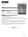
Congratulations on your purchase of the Extech 380405 Capacitance Decade Box. This
device offers 5 decades of capacitance ranges from 100pF to 11.111uF (in 100pF steps).
Slide switches allow easy addition and subtraction of capacitance values. Binding posts (3)
offer simple and secure connections. Careful use of this decade box will provide years of
reliable service.
Specifications
Capacitance ranges 100pF to 11.111uF in 100pF steps
Internal Residual Cap: 50pF maximum
Voltage limit 50VDC (non-polarized capacitors)
Connection Three (3) binding posts
Accuracy 5% (< =1uF: 1kHz test frequency; > 1uF: 100Hz test frequency)
Operating conditions Temperature: 0 to 50
o
C (32 to 122
o
F) / Humidity: < 80%RH
Dimensions/Weight 14.7 x 11.7 x 3.3cm (5.79 x 4.61 x 1.3") / Approx. 312g (0.69 lbs)
Operation
Binding Post Connections
The binding posts can be used for connections in several ways:
1. A banana plug can be inserted directly into the posts.
2. Bare wire can be threaded through the post after it has been unscrewed. Once the bare wire is threaded, tighten the posts as necessary.
3. Alligator clips can be used but use caution not to strip the post threads or plastic post housing.
The Capacitance output is available on the RED and the BLACK binding posts. The WHITE post is case ground and is typically not used. Connect the
positive lead of the device under test to the RED post. Connect the negative lead to the BLACK post. Use the WHITE grounding post only if the device
under test will be grounded to the 380405 case.
Range Selection
The 20 front panel switches are used to select the capacitance that will be output on the RED and BLACK terminals. When a switch is set to the IN
position, the value printed above the switch is added to the total capacitance available at the posts. When the switch is set to OUT it is excluded from
the total capacitance. If all of the switches are set to OUT, the total output capacitance will be zero (+ 50pF residual capacitance – approx).
For example, if the desired output value is 10.5uF, set the following switches to the IN position: 4uF, 3uF, 2uF, 1uF, 0.4uF, and 0.1uF.
Testing
This device can be used to verify the calibration integrity of multimeters, LCR meters, calibrators, etc. Connect as described in the Binding Post
Connections section above, and then set the capacitance switches to output the desired capacitance. Ensure that the voltage supplied by the device
under test is not greater than 50VDC. The device under test should read the value of capacitance selected on the tester. If it does not, the device
under test may need calibration, adjustment, or repair.
Copyright © 2013-2018 FLIR Systems, Inc.
All rights reserved including the right of reproduction in whole or in part in any form
ISO-9001 Certified
www.extech.com
-
 1
1

FLIR 380405 User manual
- Type
- User manual
- This manual is also suitable for
Ask a question and I''ll find the answer in the document
Finding information in a document is now easier with AI
Related papers
Other documents
-
HP 4440b User manual
-
Elenco Electronics CS-600 User manual
-
ETS 910 User manual
-
-
-
YSI 35 Conductance Meter Owner's manual
-
Tektronix AM 502 User manual
-
 Mark Levinson 32 User manual
-
-
HP (Hewlett-Packard) 4274A User manual
