
User’s Manual
Broadband Bandwidth Controller
Model No:SP883
http://www.micronet.info
CE Mark Warning
This equipment complies with the requirements relating to
electromagnetic compatibility, EN55022 class A for ITE, the essential
protection requirement of Council Directive 89/336/EEC on the
approximation of the laws of the Member States relating to
electromagnetic compatibility.
FCC Certifications
This Equipment has been tested and found to comply with the limits for a Class A digital
device, pursuant to Part 15 of the FCC rules. These limits are designed to provide
reasonable protection against harmful interference in a residential installation. This
equipment generates, uses and can radiate radio frequency energy and, if not installed
and used in accordance with the instructions, may cause harmful interference to radio
communications. However, there is no guarantee that interference will not occur in a
particular installation. If this equipment does cause harmful interference to radio or
television reception, which can be determined by turning the equipment off and on, the
user is encouraged to try to correct the interference by one or more of the following
measures:
- Reorient or relocate the receiving antenna.
- Increase the separation between the equipment and receiver.
- Connect the equipment into an outlet on a circuit different from that to which the
receiver is connected.
- Consult the dealer or an experienced radio/TV technician for help.
This device complies with Part 15 of the FCC Rules. Operation is subject to the
following two conditions: (1) this device may not cause harmful interference, and (2)
this device must accept any interference received; including interference that may
cause undesired operation.
Company has an on-going policy of upgrading its products and it may be
possible that information in this document is not up-to-date. Please check with
your local distributors for the latest information. No part of this document can be
copied or reproduced in any form without written consent from the company.
Trademarks:
All trade names and trademarks are the properties of their respective companies.
Copyright © 2003, All Rights Reserved.
Document Version: 2.0

Contents
CONTENTS OF PACKAGE ......................................................1
BANDWIDTH CONTROLLER OVERVIEW.........................1
HARDWARE DESCRIPTION...................................................3
BANDWIDTH CONTROLLER SOFTWARE
(CONFIGURATION TOOL) DESCRIPTION.........................5
SYSTEM.......................................................................................9
INTERFACE..............................................................................40
ADDRESS...................................................................................48
SCHEDULE ...............................................................................67
QOS.............................................................................................70
POLICY......................................................................................72
CONTENT FILTERING...........................................................81
VIRTUAL SERVER..................................................................85
LOG.............................................................................................94
ALARM ....................................................................................101
ACCOUNTING REPORT ......................................................105
STATISTICS.............................................................................116
STATUS.....................................................................................120
TROUBLE-SHOOTING.........................................................134
SETUP EXAMPLES................................................................140
SPECIFICATIONS..................................................................143

1
Contents of Package
BANDWIDTH CONTROLLER Overview
The Bandwidth Controller provides five 10/100Mbit Ethernet network
interface ports, which are the Internal/LAN and External/WAN ports.
It also provides easily operated software WebUI that allows users to
set system parameters or monitor network activities using a web
browser.
BANDWIDTH CONTROLLER security feature
Some functions that are available in this device are: Content Filter,
Proxy Server, Hacker invasion alarm, Packet monitor log, Policy, etc.
2
BANDWIDTH CONTROLLER installation
This product is a pure hardware Bandwidth Controller. Therefore
the installation is much easier than software one. First the user has
to prepare two network cables, and connect them to the LAN and
WAN connectors respectively. The LAN interface has to connect to
the office’s LAN network on the same HUB/Switch. The WAN
interface has to connect with an WAN router, DSL modem, or Cable
modem.
BANDWIDTH CONTROLLER function setting
The Bandwidth Controller has a built in WebUI (Web User Interface).
All configurations and management are done through the WebUI
using an Internet web browser.
BANDWIDTH CONTROLLER monitoring function
The Bandwidth Controller provides monitoring functions, which
contains traffic log, event log, traffic alarm, event alarm, and traffic
statistics. Traffic alarm records the packets of hacker invasions.
Not only does the Bandwidth Controller log these attacks, it can be
set up to send E-mail alerts to the Administrator automatically for
immediate hacker’s invasion crisis management.
BANDWIDTH CONTROLLER supporting protocols
The Bandwidth Controller supports all the TCP, UDP and ICMP
protocols, such as HTTP, TELNET, SMTP, POP3, FTP, DNS, PING,
etc. System Administrators can set up proprietary protocols
according to operating requirements.

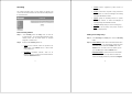
3
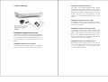
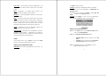
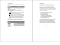
Hardware Description
External Port (WAN): Use this port to connect to the external router,
DSL modem, or Cable modem.
Internal Port (LAN)
: Use this port to connect to the internal network
of the office.
Reset
: Reset the Bandwidth Controller to the original default
settings.
DC Power
: Connect one end of the power supply to this port, the
other end to the electrical wall outlet.
4
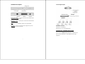
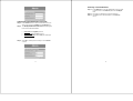
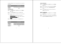
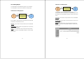
Connecting Example:
Bandwidth Controller:
Internal Port = 192.168.1.1
External Port = x.x.x.x (provided by ISP)
Connection Type: 10/100 Mbps Cable Connection
All ports supports MDI/MDI-X auto crossover capability that is the
port can connect either the PC or hub without crossover cable
adjustment.

5
BANDWIDTH CONTROLLER Software
(configuration tool) description
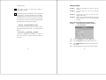
BANDWIDTH CONTROLLER configuration tool: Web
UI
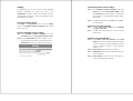
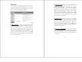
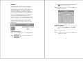
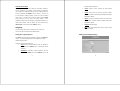
The main menu functions are located on the left-hand side of the
screen, and the display window will be on the right-hand side. The
main functions include items, which are: System, Interface,
Address, Service, Schedule, QoS, Policy, Content Filter, Virtual
Server, Log, Alarm, Accounting Report, Statistics, and Status.
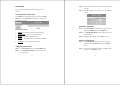
Quick Setup
Web UI Configuration example
Step 1:
Connect both the Administrator’s PC and the LAN port of the
Bandwidth Controller to a hub or switch. Make sure there is a link
light on the hub/switch for both connections. The Bandwidth
Controller has an embedded web server used for management and
configuration. Use a web browser to display the configurations of the
Bandwidth Controller (such as Internet Explorer 4(or above) or
Netscape 4.0(or above) with full java script support). The default IP
address of the Bandwidth Controller is 192.168.1.1 with a subnet
mask of 255.255.255.0. Therefore, the IP address of the Administrator
PC must be in the range between 192.168.1.2/24– 192.168.1.254/24.
If the company’s LAN IP Address is not subnet of 192.168.1.0, (i.e.
6
Internal IP Address is 172.16.0.1) the Administrator must change
his/her PC IP address to be within the same range of the LAN subnet
(i.e. 192.168.0.0). Reboot the PC if necessary.
By default, the Bandwidth Controller is shipped with its DHCP Server
function enabled. This means the client computers on the LAN
network including the Administrator PC can set their TCP/IP settings to
automatically obtain an IP address from the Bandwidth Controller.
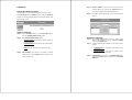
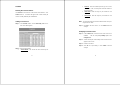
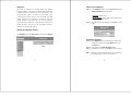
The following table is a list of private IP addresses. These addresses
may not be used as a WAN IP address.
10.0.0.0 ~ 10.255.255.255
172.16.0.0 ~ 172.31.255.255
192.168.0.0 ~ 192.168.255.255
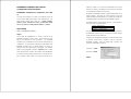
Once the Administrator PC has an IP address on the same network as
the Bandwidth Controller, open up an Internet web browser and type
in http://192.168.1.1 in the address bar.
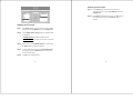
A pop-up screen will appear and prompt for a username and password.
A username and password is required in order to connect the
Bandwidth Controller. Enter the default login username and
password of Administrator (see below).
Username: admin
Password: admin
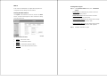
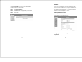
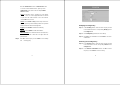
Step 2:

7
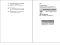
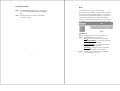
After entering the username and password, the Bandwidth Controller
WebUI screen will display. Select the Interface tab on the left menu
and enter proper Layer 3 network setup information. (For example)
LAN Interface IP Address 192.168.1.1
Netmask 255.255.255.0
WAN Interface IP address 211.22.93.2
Netmask 255.255.255.0
Default Gateway 211.22.93.1
Note: The above figures are only examples. Please fill in the
appropriate IP address information provided to you by the ISP.
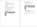
Click on the Policy tab from the main function menu, and then click on
Outgoing from the sub-function list.
Click on New Entry button.
When the New Entry option appears, then enter the following
configuration:
Source Address – select “Inside_Any”
Destination Address – select “Outside_Any”
8
Service - select “ANY”
Action - select “Permit”
Click on OK to apply the changes.
Make sure that all the computers that are connected to the LAN port
have their Default Gateway IP Address set to the Bandwidth
Controller’s LAN IP Address (i.e. 192.168.1.1). At this point, all the
computers on the LAN network should gain access to Internet
immediately. If a firewall filter function is required, please refer to the
Policy section.

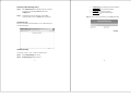
9
System
The Bandwidth Controller Administration and monitoring control is set
by the System Administrator. The System Administrator can add or
modify system settings and monitoring mode. The sub
Administrators can only read system settings but not modify them. In
System, the System Administrator can:
(1) Add and change the sub Administrator’s names and passwords.
(2) Back up all Bandwidth Controller configuration into local files.
(3) Set up alerts for Hackers invasion.
The thirteen sub functions under System are Admin, Setting,
Date/Time, Language, Permitted IPs, Multiple NAT, Hacker Alert,
Route Table, DHCP, DNS Proxy, DDNS, Logout and Software
Update.
10
Admin: has control of user access to the system. He/she can
add/remove users and change passwords.
Setting
: The Administrator may use this function to backup
Bandwidth Controller configurations and export (save) them to an
“Administrator” computer or anywhere on the network; or restore a
configuration file to the Bandwidth Controller; or restore the system
back to default factory settings. Under Setting, the Administrator may
enable e-mail alert notification. This will alert Administrator(s)
automatically whenever the Bandwidth Controller has experienced
unauthorized access or a network hit (hacking or flooding). Once
enabled, an IP address of a SMTP (Simple Mail Transfer protocol)
Server is required. Up to two e-mail addresses can be entered for
the alert notifications.
Date/Time
: Enables the Bandwidth Controller to be synchronized
either with an Internet Server time or with the client computer’s clock.
Language
: Bandwidth Controller provides Traditional Chinese
Version,Simplified Chinese Version and English version for you to
choose.
Permitted IPs
: Enables the Administrator to authorize specific
LAN/WAN IP address for management.
Multiple NAT
: Allows local port to set multiple subnet works and
connect with the Internet through different WAN IP Addresses.
Hacker Alert
: When abnormal conditions occur, the system will send
an e-mail alert to notify the Administrator, and also display warning
messages in the Event window of Alarm.

11
Route Table: Use this function to enable the Administrator to add
static routes for the networks when the dynamic route is not efficient
enough.
DHCP
: Administrator can configure DHCP (Dynamic Host
Configuration Protocol) settings for the LAN network.
DNS Proxy
: To make the Bandwidth Controller act as a DNS Server
for the LAN network.
DDNS
: The Dynamic DNS (require Dynamic DNS Service) allows
you to alias a dynamic IP address to a static hostname, allowing your
device to be more easily accessed by specific name. When this
function is enabled, the IP address in Dynamic DNS Server will be
automatically updated with the new IP address provided by ISP.
Logout
: Administrator logs out the Bandwidth Controller. This
function protects your system while you are away.
Software Update
: Administrators may visit distributor’s web site to
download the latest firmware. Administrators may update the
Bandwidth Controller firmware to maximize its performance and stay
current with the latest fixes for intruding attacks.
Admin
On the left-hand menu, click on System, and then select Admin
below it. The current list of Administrator(s) shows up.
Settings of the Administration table:
Admin Name: The username of Administrators for the system. The
12
user admin cannot be removed.
Privilege
: The privileges of Administrators (Admin or Sub Admin)
The username of the main Administrator is Administrator with
read/write privilege.
Sub Admins may be created by the Admin by clicking
New Sub
Admin
. Sub Admins have read only privilege.
Configure
: Click Modify to change the “Sub Administrator’s”
password and click Remove to delete a “Sub Administrator.”
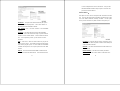
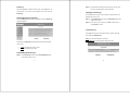
Adding a new Sub Administrator:
Step 1. In the Admin window, click the New Sub Admin button to
create a new Sub Administrator.
Step 2. In the Add New Sub Administrator window:
• Sub Admin Name: enter the username of new Sub
Admin.
• Password: enter a password for the new Sub Admin.
• Confirm Password: enter the password again.
Step 3. Click OK to add the user or click Cancel to cancel the
addition. (Match whole word only)

13
Changing the Sub-Administrator’s Password:
Step 1. In the Admin window, locate the Administrator name you
want to edit, and click on Modify in the Configure field.
Step 2. The Modify Administrator Password window will appear.
Enter in the required information:
• Password
: Enter original password.
• New Password
: Enter new password.
• Confirm Password
: Enter the new password again.
Step 3. Click OK to confirm password change or click Cancel to
cancel it.
14
Removing a Sub Administrator:
Step 1. In the Admin table, locate the Administrator name you want
to edit, and click on the Remove option in the Configure
field.
Step 2. The Remove confirmation pop-up box will appear.
Step 3. Click OK to remove that Sub Admin or click Cancel to
cancel.

15
Settings
The Administrator may use this function to backup Bandwidth
Controller configurations and export (save) them to an
“Administrator” computer or anywhere on the network; or restore a
configuration file to the device; or restore the Bandwidth Controller
back to default factory settings.
Entering the Settings window:
Click Setting in the Administrator menu to enter the Settings
window. The Bandwidth Controller Configuration settings will be
shown on the screen.
Exporting Bandwidth Controller settings:
Step 1. Under Bandwidth Controller Configuration, click on the
Download button next to Export System Settings to Client.
Step 2. When the File Download pop-up window appears, choose
the destination place in which to save the exported file. The
Administrator may choose to rename the file if preferred.
16
Importing Bandwidth Controller settings:
Step 1. Under Bandwidth Controller Configuration, click on the
Browse button next to Import System Settings. When
the Choose File pop-up window appears, select the file to
which contains the saved Bandwidth Controller Settings,
then click OK.
Step 2. Click OK to import the file into the System or click Cancel
to cancel importing.
Restoring Factory Default Settings:
Step 1. Select Reset Factory Settings under Bandwidth
Controller Configuration.
Step 2. Click OK at the bottom-right of the screen to restore the
factory settings.
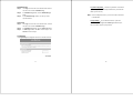
Enabling E-mail Alert Notification:
Step 1. Select Enable E-mail Alert Notification under E-Mail
Settings. This function will enable the Bandwidth Controller
to send e-mail alerts to the System Administrator when the
network is attacked by hackers or when emergency
conditions occur.
Step 2. SMTP Server IP: Enter SMTP server’s IP address.
Step 3. E-Mail Address 1: Enter the first e-mail address to receive
the alarm notification.
Step 4. E-Mail Address 2: Enter the second e-mail address to
receive the alarm notification. (Optional)

17
Step 5. Click OK on the bottom-right of the screen to enable E-mail
alert notification.
Web Management (WAN Interface)
The administrator can change the port number used by HTTP port
anytime. (Remote UI management) The number is the port number,
which you can access the Web Management Interface from WAN port.
Web Browsers use port 80 by default for connection. For security
reasons, you can change the port number or clear the check box to
disable it in Interface \ WAN Interface \ WEB UI
MTU Setting
The administrator can modify the networking packet length. PPPoE
uses a Maximum Transmission Unit (MTU) setting of 1492 bytes,
while all client computers (Windows IE browsers) usually use the
default MTU of 1500 bytes. The existing Internet standards to address
this issue, however, some web sites do not conform to these
standards, which causes the access problem.
18
To-Appliance Packets Log
Once this function is enabled, every packet to this appliance will be
recorded for system manager to trace.
System Reboot
Once this function is selected, the Bandwidth Controller will be
rebooting.
Date/Time
This option can synchronize the system clock of the appliance. This
will allow the logs to be time stamped correctly according to the
computer clock time.

19
Follow these steps to sync to an Internet Time Server
Step 1. Enable synchronization by checking the box.
Step 2. Click the down arrow to select the offset time from GMT.
Step 3. Enter the Server IP Address or Server name with which you
want to synchronize.
Step 4. Update system clock every minutes; You can set the
interval time to synchronize with outside servers. If you set it
to 0, it means the device will not synchronize automatically.
Follow this step to sync to your computer’s clock.
Step 1. Click on the Sync button.
Step 2. Click the OK button below to apply the setting or click
Cancel to discard changes.
20
Language
The software provides Traditional Chinese Version, Simplified
Chinese Version and English version for you to choose.
Step 1. Select the language version you want(Traditional Chinese
Version,Simplified Chinese Version and English
version).
Step 2. Click OK to change the language version or click Cancel to
discard changes.

21
Permitted IPs
Only the authorized IP address is permitted to manage the Bandwidth
Controller.
Step 1. Click New Entry button.
Step 2. In IP Address field, enter the LAN IP address or WAN IP
address.
Netmask
: This is the netmask of the LAN network. The default
netmask of the Bandwidth Controller is 255.255.255.0.
Ping
: Select this to allow the LAN network to ping the IP Address
of the Bandwidth Controller. If set to enable, the Bandwidth
Controller will respond to ping packets from the LAN network.
Web UI
: Select this to allow the Bandwidth Controller WebUI to
be accessed from the LAN network.
Step 3. Click OK to add Permitted IPs or click Cancel to discard
changes.
22
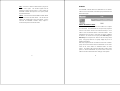
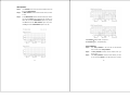
Multiple NAT
Multiple NAT allows local port to set multiple sub networks and
connect with the Internet through different WAN IP Addresses.
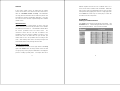
For instance: The lease line of a company applies several real IP
Addresses 168.85.88.0/24,and the company is divided into R&D
department, service, sales department, procurement department,
accounting department, the company can distinguish each department
by different sub networks for the purpose of convenient management.
The settings are as the following:
1. R&D department sub network:
192.168.1.11/24(LAN) ÅÆ 168.85.88.253(WAN)
2. Service department sub network:
192.168.2.11/24(LAN) ÅÆ 168.85.88.252(WAN)
3. Sales department sub network:
192.168.3.11/24(LAN) ÅÆ 168.85.88.251(WAN)
4. Procurement department sub network:
192.168.4.11/24(LAN) ÅÆ 168.85.88.250(WAN)
5. Accounting department sub network:
192.168.5.11/24(LAN) ÅÆ 168.85.88.249(WAN)
The first department(R&D department) was set while setting interface
IP, the other four ones have to be added in Multiple NAT; after
completing the settings, each department use the different WAN IP
Address to connect to the internet. The settings of each department
are as the following
Service IP Address: 192.168.2.1
Subnet Mask: 255.255.255.0
Default Gateway: 192.168.2.11

23
The other departments are also set by groups; this is the function of
Multiple NAT.
Add Multiple NAT
Step 1. Click Multiple NAT in the System menu to enter Multiple
NAT window.
Step 2. Click the New Entry button below to add Multiple NAT.
Step 3. Enter the IP Address in the website name column of the new
window.
• External Interface IP
: WAN IP address (public IP).
• Alias IP of internal Interface
: LAN IP address (private IP).
• Netmask
: Netmask of your network.
Step 4. Click OK to add Multiple NAT or click Cancel to discard
changes.
24
Modify Multiple NAT
Step 1. Click Multiple NAT in the System menu to enter Multiple
NAT window.
Step 2. Find the IP Address you want to modify and click Modify.
Step 3. Enter the new IP Address in Modify Multiple NAT IP
window.
Step 4. Click the OK button below to change the setting or click
Cancel to discard changes.
Remove Multiple NAT
Step 1. Click Multiple NAT in the System menu to enter Multiple
NAT window.
Step 2. Find the IP Address you want to delete and click Remove.
Step 3. A confirmation pop-up box will appear, click OK to delete the
setting or click Cancel to discard changes.

25
Hacker Alert
The Administrator can enable the Bandwidth Controller’s auto detect
functions in this section. When abnormal conditions occur, the system
will send an e-mail alert to notify the Administrator, and also display
warning messages in the Event window of Alarm.
Detect SYN Attack: Select this option to detect TCP SYN attacks
that hackers send to server computers continuously to block or cut
down all the connections of the servers. These attacks will prevent
valid users from connecting to the servers. After enabling this
function, the System Administrator can enter the number of SYN
packets per second that is allow to enter the network/system. Once
the SYN packets exceed this limit, the activity will be logged in Alarm
and an email alert is sent to the Administrator. The default SYN flood
threshold is set to 200 Pkts/Sec.
26
Detect ICMP Flood: Select this option to detect ICMP flood
attacks. When hackers continuously send PING packets to all the
machines of the LAN networks or to the system, your network is
experiencing an ICMP flood attack. This can cause traffic congestion
on the network and slows the network down. After enabling this
function, the System Administrator can enter the number of ICMP
packets per second that is allowed to enter the network. Once the
ICMP packets exceed this limit, the activity will be logged in Alarm
and an email alert is sent to the Administrator. The default ICMP
flood threshold is set to 1000 Pkts/Sec.
Detect UDP Flood: Select this option to detect UDP flood attacks.
A UDP flood attack is similar to an ICMP flood attack. After enabling
this function, the System Administrator can enter the number of UDP
packets per second that is allow to enter the network. Once the UDP
packets exceed this limit, the activity will be logged in Alarm and an
email alert is sent to the Administrator. The default UDP flood
threshold is set to 1000 Pkts/Sec.
Detect Ping of Death Attack: Select this option to detect the
attacks of tremendous trash data in PING packets that hackers send
to cause System malfunction. This attack can cause network speed
to slow down, or even make it necessary to restart the computer to get
a normal operation.

27
Detect Tear Drop Attack: Select this option to detect tear drop
attacks. These are packets that are segmented to small packets with
negative length. Some Systems treat the negative value as a very
large number, and copy enormous data into the System to cause
System damage, such as a shut down or a restart.
Detect IP Spoofing Attack: Select this option to detect spoof
attacks. Hackers disguise themselves as trusted users of the
network in Spoof attacks. They use a fake identity to try to pass
through the System and invade the network.
Filter IP Source Route Option: Each IP packet can carry an
optional field that specifies the replying address that can be different
from the source address specified in packet’s header. Hackers can
use this address field on disguised packets to invade LAN networks
and send LAN networks’ data back to them.
Detect Port Scan Attack: Select this option to detect the port
scans hackers use to continuously scan networks on the Internet to
detect computers and vulnerable ports that are opened by those
computers.
Detect Land Attack: Some Systems may shut down when
receiving packets with the same source and destination addresses,
28
the same source port and destination port, and when SYN on the TCP
header is marked. Enable this function to detect such abnormal
packets.
Default Packet Deny: Denies all packets from passing the
Bandwidth Controller. A packet can pass only when there is a policy
that allows it to pass.
Note: After enabling the needed detect functions, click OK to
activate the changes.

29
Route Table
In this section, the Administrator can add static routes for the
networks.
Entering the Route Table screen:
Click System on the left-hand side menu bar, and then click Route
Table below it. The Route Table window appears, in which current
route settings are shown.
Route Table functions:
• Interface: Destination network, LAN or WAN networks.
• Destination IP
: IP address of destination network.
• Netmask
: Netmask of destination network.
• Gateway
: Gateway IP address for connecting to destination
network.
• Configure
: Change settings in the route table.
Adding a new Static Route:
Step 1. In the Route Table window, click the New Entry button.
Step 2. In the Add New Static Route window, enter new static
route information.
30
Step 3. In the Interface field’s pull-down menu, choose the network
to connect.
Step 4. Click OK to add the new static route or click Cancel to
cancel.
Modifying a Static Route:
Step 1. In the Route Table menu, find the route to edit and click the
corresponding Modify option in the Configure field.
Step 2. In the Modify Static Route window, modify the necessary
routing addresses.
Step 3. Click OK to apply changes or click Cancel to cancel it.
Removing a Static Route:
Step 1. In the Route Table window, find the route to remove and
click the corresponding Remove option in the Configure
field.
Step 2. In the Remove confirmation pop-up box, click OK to confirm
removing or click Cancel to cancel it.

31
DHCP
In the section, the Administrator can configure DHCP (Dynamic Host
Configuration Protocol) settings for the LAN network.
Entering the DHCP window:
Click System on the left-hand side menu bar, and then click DHCP
below it. The DHCP window appears in which current DHCP settings
are shown on the screen.
Dynamic IP Address functions:
• Subnet
: LAN network’s subnet.
• NetMask
: LAN network’s netmask.
• Gateway
: LAN network’s gateway IP address.
• Broadcast
: LAN network’s broadcast IP address.
32
Enabling DHCP Support:
Step 1. In the Dynamic IP Address window, click Enable DHCP
Support.
Domain Name
: The Administrator may enter the name of the
LAN network domain if preferred.
Domain Name Server
: Enter in the IP address of the DNS
Server to be assigned to the LAN network.
Client IP Address Range 1
: Enter the starting and the ending IP
address dynamically assigning to DHCP clients.
Client IP Address Range 2
: Enter the starting and the ending IP
address dynamically assigning to DHCP clients. (Optional)
Step 2. Click OK to enable DHCP support.

33
DNS-Proxy
The Bandwidth Controller’s Administrator may use the DNS Proxy
function to make the Bandwidth Controller act as a DNS Server for the
LAN network. All DNS requests to a specific Domain Name will be
routed to the Bandwidth Controller’s IP address. For example, let’s
say an organization has their mail server (i.e., mail.dfl300.com) in the
LAN network (i.e. 192.168.10.10). The outside Internet world may
access the mail server of the organization easily by its domain name,
providing that the Administrator has set up Virtual Server or Mapped IP
settings correctly. However, for the users in the LAN network, their
WAN DNS server will assign them a public IP address for the mail
server. So for the LAN network to access the mail server
(mail.dfl300.com), they would have to go out to the Internet, then come
back through the Bandwidth Controller to access the mail server.
Essentially, the LAN network is accessing the mail server by a real
public IP address, while the mail server serves their request by a NAT
address and not a real one. This odd situation occurs when there are
servers in the LAN network and they are bound to real IP addresses.
To avoid this, set up DNS Proxy so all the LAN network computers will
use the Bandwidth Controller as a DNS server, which acts as the DNS
Proxy.
Note: If you want to use the DNS Proxy function of the Bandwidth
Controller, the end user’s main DNS server IP address should
be the same IP Address as the Bandwidth Controller.
34
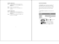
Entering the DNS Proxy window:
Click on System in the menu bar, and then click on DNS Proxy below
it. The DNS Proxy window will appear.
Below is the information needed for setting up the DNS Proxy:
• Domain Name
: The domain name of the server.
• Virtual IP Address
: The virtual IP address respective to DNS
Proxy.
• Configure
: Modify or remove each DNS Proxy policy.
Adding a new DNS Proxy:
Step 1: Click on the New Entry button and the Add New DNS
Proxy window will appear.
Step 2: Fill in the appropriate settings for the domain name and
virtual IP address.
Step 3: Click OK to save the policy or Cancel to cancel.

35
Modifying a DNS Proxy:
Step 1: In the DNS Proxy window, find the domain name to be
modified and click the corresponding Modify option in the
Configure field.
Step 2: Make the necessary changes needed.
Step 3: Click OK to save changes or click on Cancel to cancel
modifications.
Removing a DNS Proxy:
Step 1: In the DNS Proxy window, find the domain name to be
removed and click the corresponding Remove option in the
Configure field.
Step 2: A confirmation pop-up box will appear, click OK to remove
the DNS Proxy or click Cancel.
36
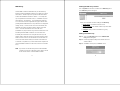
Dynamic DNS (DDNS)
The Dynamic DNS (require Dynamic DNS Service) allows you to
alias a dynamic IP address to a static hostname, allowing your
device to be more easily accessed by specific name. When this
function is enabled, the IP address in Dynamic DNS Server will
be automatically updated with the new IP address provided by
ISP.
Click Dynamic DNS in the System menu to enter Dynamic DNS
window.
The nouns in Dynamic DNS window:
• ! (Update Status)
: 【 Connecting; Update succeed;
Update fail; Unidentified error】.
• Domain name
: Enter the password provided by ISP.
• External IP Address
: IP Address of the WAN port.
• Modify
: Modify dynamic DNS settings. Click Modify to
change the DNS parameters; click Delete to delete the
settings.
Page is loading ...
Page is loading ...
Page is loading ...
Page is loading ...
Page is loading ...
Page is loading ...
Page is loading ...
Page is loading ...
Page is loading ...
Page is loading ...
Page is loading ...
Page is loading ...
Page is loading ...
Page is loading ...
Page is loading ...
Page is loading ...
Page is loading ...
Page is loading ...
Page is loading ...
Page is loading ...
Page is loading ...
Page is loading ...
Page is loading ...
Page is loading ...
Page is loading ...
Page is loading ...
Page is loading ...
Page is loading ...
Page is loading ...
Page is loading ...
Page is loading ...
Page is loading ...
Page is loading ...
Page is loading ...
Page is loading ...
Page is loading ...
Page is loading ...
Page is loading ...
Page is loading ...
Page is loading ...
Page is loading ...
Page is loading ...
Page is loading ...
Page is loading ...
Page is loading ...
Page is loading ...
Page is loading ...
Page is loading ...
Page is loading ...
Page is loading ...
Page is loading ...
Page is loading ...
Page is loading ...
Page is loading ...
-
 1
1
-
 2
2
-
 3
3
-
 4
4
-
 5
5
-
 6
6
-
 7
7
-
 8
8
-
 9
9
-
 10
10
-
 11
11
-
 12
12
-
 13
13
-
 14
14
-
 15
15
-
 16
16
-
 17
17
-
 18
18
-
 19
19
-
 20
20
-
 21
21
-
 22
22
-
 23
23
-
 24
24
-
 25
25
-
 26
26
-
 27
27
-
 28
28
-
 29
29
-
 30
30
-
 31
31
-
 32
32
-
 33
33
-
 34
34
-
 35
35
-
 36
36
-
 37
37
-
 38
38
-
 39
39
-
 40
40
-
 41
41
-
 42
42
-
 43
43
-
 44
44
-
 45
45
-
 46
46
-
 47
47
-
 48
48
-
 49
49
-
 50
50
-
 51
51
-
 52
52
-
 53
53
-
 54
54
-
 55
55
-
 56
56
-
 57
57
-
 58
58
-
 59
59
-
 60
60
-
 61
61
-
 62
62
-
 63
63
-
 64
64
-
 65
65
-
 66
66
-
 67
67
-
 68
68
-
 69
69
-
 70
70
-
 71
71
-
 72
72
-
 73
73
-
 74
74


