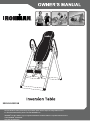
Ironman 5501 Owner's manual
- Type
- Owner's manual

5501.10-051518
The specifications of this product may vary from this photo and are subject to change without notice.
For more brand information, please visit www.IRONMAN.com
IRONMAN
®
and the "M-DOT" logo are registered trademarks of World Triathlon Corporation Official Product
of the IRONMAN
®
TRIATHLON.
Used here by permission.


1
TABLE OF CONTENTS
SERVICE-------------------------------------------------------------------------------------------------------------- 2
IMPORTANT SAFETY GUIDELINES--------------------------------------------------------------------------- 3
LABEL PLACEMENT----------------------------------------------------------------------------------------------- 6
OVERVIEW DRAWING-------------------------------------------------------------------------------------------- 7
HARDWARE & TOOLS PACK----------------------------------------------------------------------------------- 8
PARTS LIST---------------------------------------------------------------------------------------------------------- 9
ASSEMBLY----------------------------------------------------------------------------------------------------------- 10
OPERATION AND ADJUSTMENTS---------------------------------------------------------------------------- 17
STORAGE------------------------------------------------------------------------------------------------------------ 23
WARRANTY---------------------------------------------------------------------------------------------------------- 24
PARTS REQUEST FORM---------------------------------------------------------------------------------------- 25

2
SERVICE
IMPORTANT: FOR NORTH AMERICA ONLY
For damaged or defective product, questions, replacement parts or any other service support, please
contact our customer service department by the below methods:
For The Best Service, please Email:
service@paradigmhw.com
Response Time: 1-2 Business Days
Emailing us with the information above will be the best method to receive a response during peak business
hours
Website:
www.paradigmhw.com
Toll-Free:
1-844-641-7922
(8:00 AM - 5:00 PM Pacific Standard Time, Monday thru Friday)
Response time may vary via calling
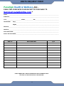
Please have the following information ready when requesting for service:
Your name
Phone number
Model number
Serial number
Part number
Proof of Purchase
For damaged or defective product please contact our customer service before returning to the store.
Paradigm Health & Wellness, Inc.
1189 Jellick Ave.
City of Industry, CA 91748, USA

3
IMPORTANT SAFETY GUIDELINES

4
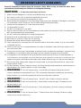
IMPORTANT SAFETY GUIDELINES
Read all instructions before using the Inversion Table. When using an Inversion table, basic
precautions should always be followed, including the following:
WARNING - To reduce the risk of injury to persons:
1. Make sure your equipment is correctly assembled before you use it.
2. Be sure all screws, nuts, and bolts are tightened prior to use.
3. Only one person should use the equipment at a time.
4. Never operate this equipment if it is not working properly, has been dropped, or damaged. If a problem
is Encountered, contact Customer Service before using the equipment again.
5. Always use this equipment on a clear and level surface.
6. For Household Use Only.
7. Do NOT use outdoors or near water.
8. Use the inversion table only for its intended use as described in this manual. Do NOT use attachments
NOT recommended by the manufacturer.
9. Do NOT wear loose clothing when using the equipment.
10. Keep all hands and feet away from any moving parts.
11. Never drop or insert any object into any opening.
12. Always wear shoes when using the inversion table.
13. Close supervision is necessary when the inversion table is used near children, or by or near invalids
or disabled persons.
14. Listen to your body. It is recommended that you rotate up and down slowly. Dizziness might occur if
you come up too fast.
15. If at any time you feel faint, light-headed, or dizziness while operating the equipment, stop exercising
immediately. You should also stop exercising if you are experiencing pain or any discomfort.
16. “This appliance is NOT intended for use by persons with reduced physical, sensory or mental capabilities, or
lack of experience and knowledge, unless they have been given supervision or instruction concerning use of the
appliance by a person responsible for their safety. Keep children under the age of 13 away from this machine.”
17. Wait 2 hours after eating before using the inversion table. If you start feeling nauseous, return to the
upright position slowly.
18. For any problems, contact Customer Service. Servicing should be performed by an authorized service
representative. Our contact number is on the service page.
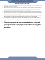
19. WARNING: - Risk of Personal Injury - Consult with your personal physician to see if
inversion equipment is appropriate for you. This is especially important for people with pre-existing
health problems. Do not use this equipment without your physician's approval.
20. WARNING: - Risk of Personal Injury – Do NOT allow children to use this machine.
21. WARNING:- Risk of Personal Injury - Keep children under the age of 13 away from the
machine while in use.
22. WARNING:- Risk of Personal Injury – Keep body parts, hair, loose clothing, and jewelry
clear of all moving parts.
23. WARNING: - Risk of Personal Injury - Tilt-back slowly when inverting. Failure to comply
could result in serious bodily injury.

5
IMPORTANT SAFETY GUIDELINES
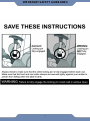
The product weighs more than 44 lbs. It is heavily
recommended that at least 2 persons assemble.
24. WARNING:- Risk of Personal Injury - Do NOT attempt to service the unit yourself.
Discontinue use and contact customer service.
25. WARNING: - To Reduce The Risk Of Personal Injury - Read And Understand All The
Instructions Before Using The Inversion Table.
Do not use this equipment if you have any of the following conditions or ailments:
Pregnancy
Extreme obesity
Middle ear infection
Hiatus hernia or Ventral hernia
Glaucoma, retinal detachment or conjunctivitis
Use of anticoagulants including Aspirin in high doses.
Spinal injury, Cerebral Sclerosis, or acutely swollen joints
Heart or circulatory disorders for which you are being treated
High blood pressure, Hypertension, Recent stroke or Transient Ischemic attack
Bone weaknesses including Osteoporosis, Unhealed fractures, Modular pins, or surgically
implanted orthopedic supports.
Do not exceed the maximum rated weight (load) and maximum
rated user height:
The Maximum Weight Capacity for this product is 275lbs / 125 kgs.
The Maximum Height Capacity for this product is 6 feet 6 inches / 198cm.
Retain this owner’s manual and keep the original purchase receipt
for future reference.
SAVE THESE GUIDELINES

6
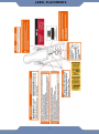
LABEL PLACEMENTS

7
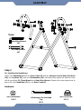
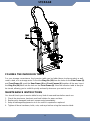
OVERVIEW DRAWING

8
HARDWARE & TOOLS PACK

9
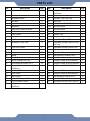
PARTS LIST
No.
Description
Qty
No.
Description
Qty
1
Backrest (#5501/#5502)
1
28
Hexagon Socket Head Cap Bolt
M8x20mm
6
2
Backrest Frame
1
29
Plastic Washers
4
3
Adjustable Boom
1
30
Foot Bar Oval End Cap
2
4
Foot Bar
1
31
Foot Cap
4
5
Adjustable Instep Frame
1
32
Flat Washer Ø13xØ6.5x1.5
6
6
Handlebar
2
033
Bolt M6x12mm
4
7
Steel Heel Holder Bracket
2
34
Bolt M6x50mm
2
8
Rear Frame
1
35
Loop Strap
1
9
Front Frame
1
36
Rubber Pad
2
10
Rod
1
37
Safety Hook
2
11
Pivot Arm
2
38
Square End Cap □33
1
12
Handlebar Foam Grip
2
39
Adjustable Instep Frame Round
End Cap
2
13
Front Heel Holder
2
40
Adjustable Instep Frame Knob
1
14
Rubber Rear Heel Holder
2
41
Adjustable Boom Knob
1
15
Spring Latch
1
42
Nylon Nut M8
7
16
Spring
1
43
Flat Washer Ø16xØ8.5x2.0
1
17
Plastic Spacer
4
44
Metal Bushing
1
18
Plastic Round End Cap
2
45
Hexagon Head Bolt M8x48mm
1
19
Flat Washer Ø16xØ8.5x1.5
14
46
Hexagon Head Bolt M10x42mm
1
20
Hexagon Socket Head Cap Bolt
M8x60mm
4
47
Flat Washer Ø18xØ10.5x2.0
1
22
Rod Cap Ø22
2
48
Nylon Nut M10
1
23
Nylon Strap
1
49
Hexagon Head Bolt M6x40mm
1
24
Cap Nut M8
4
50
Flat Washer Ø18xØ6.5x1.5
1
25
Square End Cap □30
1
51
Nylon Nut M6
1
26
Ring Pin Ø8x63.5mm
1
52
Handlebar Round End Cap Ø25
2
27
Hexagon Socket Head Cap Bolt
M8x65mm
2

10
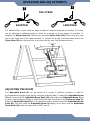
ASSEMBLY
The product weighs more than 44 lbs and should
be assembled and moved by two or more people.
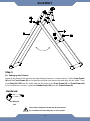
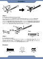
Step 1
1A. Setting up the Frames:
Stand up the base of the machine by separating the frames as shown above. Pull the Rear Frame
(8) and the Front Frame (9) as far apart as possible from each other and align the pin holes. Then
insert Ring Pin (26) from the outer side into the holes on the Rear Frame (8) and Front Frame (9)
to lock the frames in place. Install two Rubber Pads (36) onto the Front Frame (9).
(26) Ring Pin
1 PC
Hardware:

11
ASSEMBLY
Step 2
2A. Installing the Handlebars:
Attach one Handlebar (6) onto the Rear Frame (8) with two Hexagon Socket Head Cap Bolts
(20), two Cap Nuts (24), and four Flat Washers (19). Simultaneously tighten the bolts and nuts
with the provided 13, 17mm Wrench and 6mm Allen Wrench. Repeat the same steps above to
attach the other Handlebar (6) onto the Rear Frame (8).
Hardware:
(19) Flat Washers
8 PCS
(24) Cap Nut M8
4 PCS
(20) Hexagon Socket Head
Cap
4PCS
Tools:
13,17mm Wrench
1PC
6mm Allen Wrench
1PC

12
ASSEMBLY
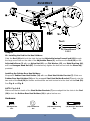
Step 3
Note: We recommend using two people for installing the backrest to the main frame.
3A. Installing the Backrest Frame:
Point the Pivot Arms (11) downwards and hold the bottom of the Backrest Frame (2) directly
above the Rubber Stopper for easier alignment. Slide the Backrest Frame (2) upwards
between both the Pivot Arms (11). Align the bolt holes on the Pivot Arms (11) with the holes on
the brackets of the Backrest Frame (2) and secure with four Hexagon Socket Head Cap Bolts
(28), four Flat Washers (19), and four Nylon Nuts (42). Simultaneously tighten the bolts and
nuts with the provided 13, 17mm Wrench and 6mm Allen Wrench.
Tools:
13,17mm Wrench
1PC
6mm Allen Wrench
1PC
(42) Nylon Nut
4PCS
(28) Hexagon Socket Head Cap Bolt
4PCS
(19) Flat Washer
4PCS
Hardware:

13
ASSEMBLY
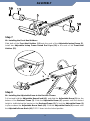
Step 4
4A. Installing the Adjustable Instep Frame:
Pull out and hold on the Adjustable Instep Frame Knob (40) before sliding the Adjustable
Instep Frame (5) out enough so it can turn. Turn it so that the adjustment holes are facing
towards the Adjustable Instep Frame Knob (40) and reinsert the Adjustable Instep Frame (5).
Release the Adjustable Instep Frame Knob (40) and adjust the Adjustable Instep Frame (5)
slightly until the Adjustable Instep Frame Knob (40) locks into place.
Step 5
5A. Installing the Foot Bar:
Align and secure the Foot Bar (4) into the bottom of the Adjustable Boom (3) with one
Hexagon Head Bolt (46), one Flat Washer (47), and one Nylon Nut (48). Simultaneously
tighten the bolt and nut with the two 13,17mm Wrenches provided.
Hardware:
Tool:
13,17mm Wrench
2 PCS
(47) Flat Washer
1PC
(48) Nylon Nut
1PC
(46) Hexagon Head Bolt
1PC

14
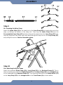
Step 6
6A. Installing the Rod for the Heel Holders:
Slide the Rod (10) with both the slots facing the Adjustable Instep Frame Knob (40) through
the large round hole on the side of the Adjustable Boom (3), and secure the Rod (10) on the
Adjustable Boom (3) with one Nylon Nut (42), one Flat Washer (43), one Metal Bushing (44),
and one Hexagon Head Bolt (45). Simultaneously tighten the bolt and nut with the Wrench(s)
provided.
Installing the Rubber Rear Heel Holders:
Wrap each Rubber Rear Heel Holder (14) with one Steel Heel Holder Bracket (7). Slide one
Rubber Rear Heel Holders (14) and the wrapped Steel Heel Holder Bracket (7) each onto the
two ends of the Rod (10) the holder and brackets are both locked in to the slots on the Rod (10).
See Fig. A and Fig. B.
NOTE: Fig. A & B
Make sure the lock teeth of the Steel Holder Brackets (7) are wedged into the slots in the Rod
(10) to lock the Rubber Rear Heel Holders (14) in place before use.
Hardware:
ASSEMBLY
Tool:
13,17mm Wrench
2 PCS
(45) Hexagon Head Bolt
1PC
(42) Nylon Nut
1PC
(43) Flat Washer
1PC
(44) Metal Bushing
1PC

15
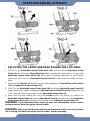
Step 7
6A. Installing the Front Heel Holders:
Slide both of the Front Heel Holders (13) onto the ends of the Adjustable Instep Frame (5).
Install two Adjustable Instep Frame Round End Caps (39) to the ends of the Front Heel
Holders (13).
Step 8
8A. Installing the Adjustable Boom to the Backrest Frame:
Pull out and hold the Adjustable Boom Knob (41), and slide the Adjustable Boom (3) into the
bottom of the Backrest Frame (2). Slide the Adjustable Boom (3) upwards until the desired
height is visible below the bracket on the Backrest Frame (2). To lock the Adjustable Boom (3)
in place release the Adjustable Boom Knob (41). Shift the Adjustable Boom (3) inwards until
the Adjustable Boom Knob (41) "POPS" down into the locked position.
ASSEMBLY

16
Step 9
9A. Preparing the Nylon Strap:
Attach the Nylon Strap (23) to the strap lock on the Loop Strap (35) by inserting the end of the
strap up through the bottom of the strap lock. Then loop the Nylon Strap (23) over the
Pre-assembled Loop Strap (35) and down through the strap lock on the Loop Strap (35). Now,
loop the strap back over itself, and insert back through the strap lock on the Loop Strap (35),
and pull tight to secure. See the illustration above.
Step 10
10A. Attaching the Nylon Straps
Attach the combined Nylon Strap (23) & Loop Strap (35) to the Backrest Frame (2). This is
done by hooking one end of the Safety Hooks (37) on the Nylon Strap (23) to the triangular tab
on the underside of the Backrest Frame (2). Then hook the other end of the Safety Hooks (37)
on the Loop Strap (35) to the triangular tab on the Front Frame (9) as shown above.
37
ASSEMBLY

17
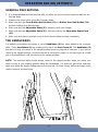
For added safety, a nylon strap has been included to restrict the degree of inversion. This strap
can be adjusted to different lengths to allow for a greater or lesser degree of inversion. To
lengthen the Nylon Strap (23), feed the top end of the Nylon Strap (23) into the strap lock, and
pull on the lower end of the strap outwards. To shorten the length, feed the bottom end of the
Nylon Strap (23) into the strap lock, and pull on the top end. See illustration above.
ADJUSTING THE BOOM
The Adjustable Boom (3) can be moved to a variety of different positions in order to
accommodate the height of the person using the inversion table. To adjust the Adjustable Boom
(3) pull out and hold the Adjustable Boom Knob (41) while sliding the Adjustable Boom (3) up
or down until the desired height is visible below the tube connected to the Backrest Frame (2).
When the Adjustable Boom (3) is in the desired position, simply release the Adjustable Boom
Knob (41), and then slide the Adjustable Boom (3) slightly up or down until the Adjustable
Boom Knob (41) locks into place with a “POP” sound.
THE STRAP
SHORTEN
LENGTHEN
OPERATION AND ADJUSTMENTS

18
GENERAL PRECAUTIONS
1. It is recommended that someone be with you while you are using this inversion table for the
first few times.
2. Always wear shoes when using the inversion table.
3. Make sure that the Front Rubber Heel Holders (13) and Rubber Rear Heel Holders (14)
are both holding your feet securely.
4. Make sure that the Adjustable Boom (3) is properly set to your height.
5. Make sure that the Adjustable Boom (3) is held securely by the Adjustable Boom Knob
(41).
6. Make sure that there is enough room for the inversion table to rotate completely.
THE HANDLEBARS
For added convenience and safety, a set of Handlebars (6) has been added to the inversion
table. These Handlebars (6) are located at the top of the Rear Frame (8). The Handlebars (6)
are there to help you return to the upright position from any degree of inversion. If you wish to
return to the upright position, and the backrest is moving too slowly, or not moving at all, slowly
pull on the handlebars until you return to the upright position.
NOTE: The inversion table should always return to the upright position when you move your
hand's closer to your starting position along the handlebars. If it does not, get off the inversion
table and adjust the height setting before your next use. Go back slowly; failure to comply could
result in serious physical injury.
OPERATION AND ADJUSTMENTS
Page is loading ...
Page is loading ...
Page is loading ...
Page is loading ...
Page is loading ...
Page is loading ...
Page is loading ...
-
 1
1
-
 2
2
-
 3
3
-
 4
4
-
 5
5
-
 6
6
-
 7
7
-
 8
8
-
 9
9
-
 10
10
-
 11
11
-
 12
12
-
 13
13
-
 14
14
-
 15
15
-
 16
16
-
 17
17
-
 18
18
-
 19
19
-
 20
20
-
 21
21
-
 22
22
-
 23
23
-
 24
24
-
 25
25
-
 26
26
-
 27
27


Ironman 5501 Owner's manual
- Type
- Owner's manual
Ask a question and I''ll find the answer in the document
Finding information in a document is now easier with AI
Related papers


Other documents
-
Exerpeutic 5503 Owner's manual
-
 Walker Edison Furniture Company HD48UBGLAG Installation guide
-
Kmart 42621331 User manual
-
 Cambridge Casual HD-240275A Installation guide
-
 Ottomanson CT600 Installation guide
-
Fitness Reality 4513 Owner's manual
-
-
ROOMS TO GO 23161906 Assembly Instructions
-
-
 Body-Solid GDCCBAR Owner's manual


