Electrical
Box
Black
CHARGE
LOAD
LIGNE
LINE
WHITE WIRE
FIL BLANC
HOT WIRE
FIL ACTIF
CHARGE
LOAD
LIGNE
LINE
WHITE WIRE
FIL BLANC
HOT WIRE
FIL ACTIF
8. Test your work
Why perform this test?
• If you miswired the GFCI it may not prevent personal injury or death due to a ground fault (electrical shock).
• If you mistakenly connect the LINE wires to the LOAD terminals, the GFCI will not reset and will not provide
power to either the GFCI receptacle face or any receptacles fed from the GFCI.
Procedure:
(a) This GFCI is shipped from the factory in the tripped condition and cannot be reset until it is wired
correctly and power is supplied to the device. Plug a lamp or radio into the GFCI (and leave it plugged
in). Turn the power ON at the service panel. Ensure that the GFCI is still in the tripped condition
by pressing the TEST button. If the lamp or radio is OFF, and the GFCI will not reset, go to the
Troubleshooting section as the Line and Load connections are reversed.
(b) Press the RESET button fully and release. If the Status Indicator Light turns ON and the lamp or radio is
ON, the GFCI has been installed correctly. If the Status Indicator Light turns or continuously blinks Red,
or the GFCI cannot be reset, go to the Self-Test Operation section.
(c) If you installed your GFCI using step 7B, plug a lamp or radio into surrounding receptacles to see which
one(s), in addition to the GFCI, lose power when you press the GFCI TEST button. Place a "GFCI
PROTECTED OUTLET" sticker on every receptacle that lost power, then press the RESET button to
reset the GFCI. DO NOT plug life saving devices into any of the receptacles that lost power.
(d) Press the TEST button (then RESET button) every month to assure proper operation. If the Status
Indicator Light does not turn Green when the RESET button is depressed and then released, or the
GFCI cannot be reset, it must be replaced.
Grounding
connection to
box (if box has a
grounding terminal)
Wire
Connector
LINE cable brings power to the GFCI
Yellow
sticker
remains
in place
to cover
the LOAD
terminals
SELF-TEST OPERATION
• A Self-Test GFCI receptacle has all the features of a conventional GFCI receptacle. In addition, this receptacle tests itself periodically to confirm
the GFCI electronics are functional. The Status Indicator Light will be solid white when the GFCI is powered from Line side and working correctly.
• Self-Test Indications: If the Status Indicator Light is solid or flashing RED a problem may exist. Press the TEST button to trip the GFCI. If unable
to Reset, replace the GFCI. NOTE: The status indicator may flash Red at power "ON" and Reset.
TROUBLESHOOTING
Turn the power OFF and check the wire connections against the appropriate wiring diagram in step 7A or 7B. Make sure that there are no
loose wires or loose connections. If the Status Indicator Light is not ON and the device is unable to reset this could be a result of no power
available. Start the test from the beginning of step 8 if you rewired any connections to the GFCI.
PK-A3081-10-00-2A
© 2015 Leviton Mfg. Co., Inc.
About Wire Connections:
Side Wire:
For Back wire -
Insert bare wire fully
and tighten terminal
clamp on conductor
ONLY
Back Wire:
For Side wire -
Loop clockwise 2/3 of the
way around screw
FOR CANADA ONLY
For warranty information and/or product returns, residents of Canada should contact Leviton in writing at Leviton Manufacturing of Canada Ltd to the attention of the Quality
Assurance Department, 165 Hymus Blvd, Pointe-Claire (Quebec), Canada H9R 1E9 or by telephone at 1 800 405-5320.
SmartlockPro is a Trademark of Leviton Manufacturing Co., Inc. registered in the United States, Canada, Mexico and China.
Self Test Cat. No. Description
GFNL1 15A-125VAC, 60Hz Tamper Resistant GFCI w/Guidelight
GFNL2 20A-125VAC, 60Hz Tamper Resistant GFCI w/Guidelight
All devices rated 20A feed-through
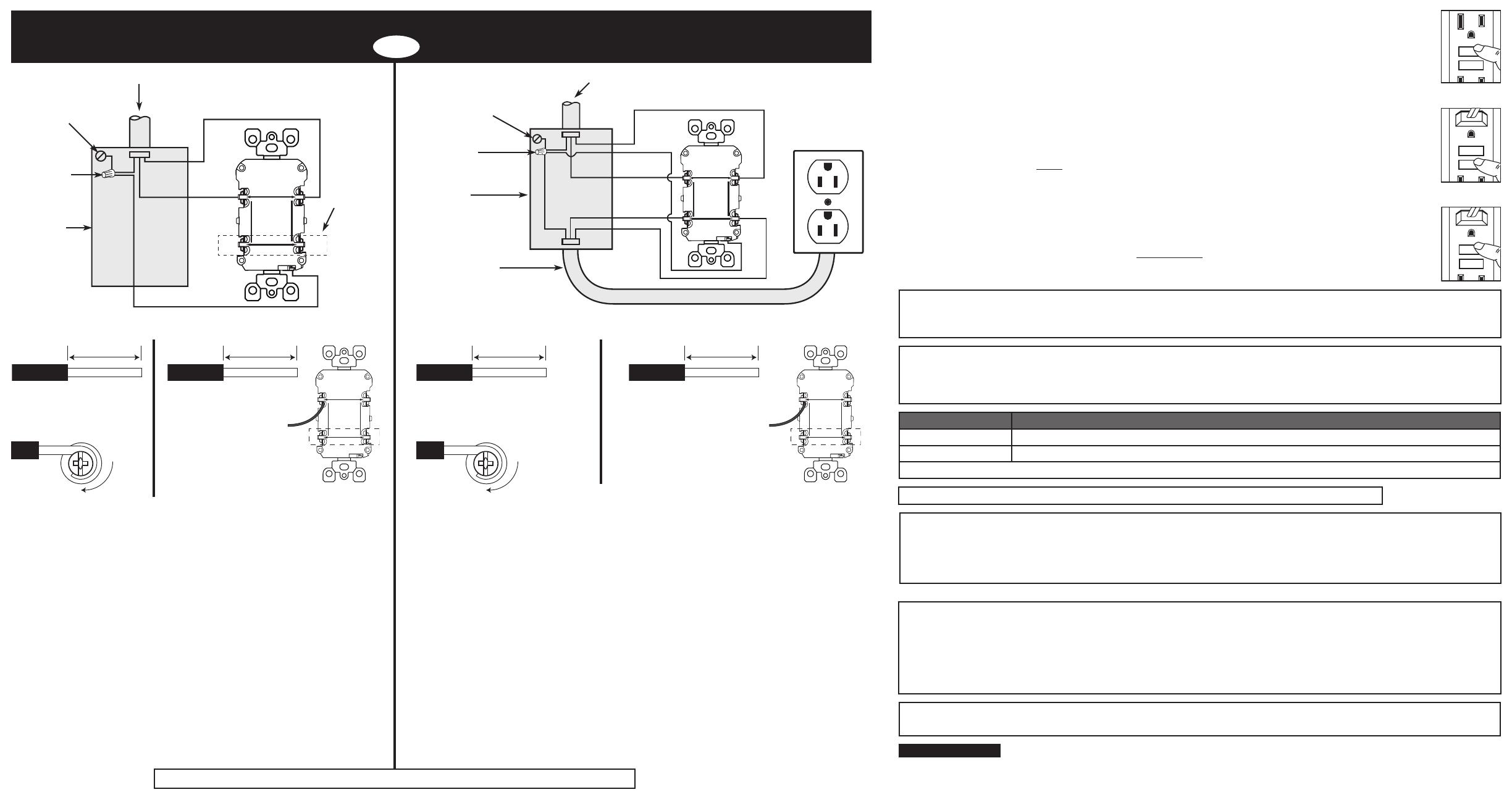
Connect the LINE cable wires to the LINE terminals:
• The white wire connects to the WHITE terminal (Silver)
• The black wire connects to the HOT terminal (Brass or Black)
Connect the grounding wire (only if there is a grounding wire):
• For a box with no grounding terminal (diagram not shown): Connect the
LINE cable's bare copper (or GREEN) wire directly to the grounding
terminal on the GFCI receptacle.
• For a box with a grounding terminal (diagram shown above): Connect
a 6-inch bare copper (or GREEN) 12 or 14 AWG wire to the grounding
terminal on the GFCI. Also connect a similar wire to the grounding
terminal on the box. Connect the ends of these wires to the LINE cable's
bare copper (or GREEN) wire using a wire connector.
If these wires are already in place, check the connections.
Complete the installation:
• Fold the wires into the box, keeping the grounding wire away from the
WHITE and HOT terminals. Screw the receptacle to the box and attach
the faceplate.
• Go to step 8.
7. Connect the wires (choose A or B)... only after reading other side completely
OR
A: One Cable (2 or 3 wires) entering the box B: Two cables (4 or 6 wires) entering the box
FCC STATEMENT
This equipment has been tested and found to comply with the limits for a Class B digital device, pursuant to part 15 of the FCC Rules. These limits are designed to provide
reasonable protection against harmful interference in a residential installation. This equipment generates, uses and can radiate radio frequency energy and, if not installed and
used in accordance with the instructions, may cause harmful interference to radio communications. However, there is no guarantee that interference will not occur in a particular
installation. If this equipment does cause harmful interference to radio or television reception, which can be determined by turning the equipment off and on, the user is encouraged
to try to correct the interference by one or more of the following measures:
• Reorient or relocate the receiving antenna. • Connect the equipment into an outlet on a circuit different from that to which the receiver is connected.
• Increase the separation between the equipment and receiver. • Consult the dealer or an experienced radio/TV technician for help.
IC STATEMENT
This device complies with Industry Canada licence-exempt RSS standard(s). Operation is subject to the following two conditions: (1) this device may not cause interference, and (2)
this device must accept any interference, including interference that may cause undesired operation of the device.
Black
Black
White
CHARGE
LOAD
LIGNE
LINE
WHITE WIRE
FIL BLANC
HOT WIRE
FIL ACTIF
CHARGE
LOAD
LIGNE
LINE
WHITE WIRE
FIL BLANC
HOT WIRE
FIL ACTIF
LINE cable brings power to the GFCI
Electrical
Box
Wire
Connector
Grounding connection
to box (if box has a
grounding terminal)
For Back wire -
Insert bare wire fully and
tighten terminal clamp on
conductor ONLY
Connect the LINE cable wires to the LINE terminals:
• The white wire connects to the WHITE terminal (Silver)
• The black wire connects to the HOT terminal (Brass or Black)
Connect the LOAD cable wires to the LOAD terminals:
• Remove the YELLOW sticker to reveal the LOAD terminals
• The white wire connects to the WHITE terminal (Silver)
• The black wire connects to the HOT terminal (Brass or Black)
Connect the grounding wires (only if there is a grounding wire):
•
Connect a 6-inch bare copper (or GREEN) 12 or 14 AWG wire to the grounding terminal on the
GFCI. If the box has a grounding terminal, also connect a similar wire to the grounding terminal
on the box. Connect the ends of these wires to the LINE or LOAD cable's bare copper (or
GREEN) wire using a wire connector. If these wires are already in place, check the connections.
Complete the installation:
• Fold the wires into the box, keeping the grounding wire away from the WHITE and HOT
terminals. Screw the receptacle to the box and attach the faceplate.
• Go to step 8.
Back Wire:
For Side wire -
Loop clockwise 2/3 of the
way around screw
About Wire Connections:
Side Wire:
LOAD cable feeds
power to other
receptacle(s)
NOTE: LINE and LOAD wiring terminals accept #10 - #14 AWG solid or stranded copper wire.
For Technical Assistance Call: 1-800-824-3005 (U.S.A. Only) 1 800 405-5320 (Canada Only) www.leviton.com
LIMITED 2 YEAR WARRANTY AND EXCLUSIONS
Leviton warrants to the original consumer purchaser and not for the benefit of anyone else that this product at the time of its sale by Leviton is free of defects in materials and workmanship
under normal and proper use for two years from the purchase date. Leviton’s only obligation is to correct such defects by repair or replacement, at its option. For details visit www.leviton.
com or call 1-800-824-3005. This warranty excludes and there is disclaimed liability for labor for removal of this product or reinstallation. This warranty is void if this product is installed
improperly or in an improper environment, overloaded, misused, opened, abused, or altered in any manner, or is not used under normal operating conditions or not in accordance with
any labels or instructions. There are no other or implied warranties of any kind, including merchantability and fitness for a particular purpose, but if any implied warranty
is required by the applicable jurisdiction, the duration of any such implied warranty, including merchantability and fitness for a particular purpose, is limited to two years. Leviton is
not liable for incidental, indirect, special, or consequential damages, including without limitation, damage to, or loss of use of, any equipment, lost sales or profits or
delay or failure to perform this warranty obligation. The remedies provided herein are the exclusive remedies under this warranty, whether based on contract, tort or otherwise.
This product is covered by U.S. Patent Nos. 6,040,967; 6,246,558; 6,282,070; 6,381,112; 6,437,953; 6,646,838; 6,657,834; 6,788,173; 6,864,766; 6,944,001; 7,336,458; 7,355,117;
7,400,479; 7,463,124; 7,697,252; 7,737,809; 7,764,151; 7,820,909; 7,862,350; 7,868,719; 7,907,371; 8,004,804; 8,054,595; 8,130,480; 8,242,362; 8,444,309; 8,547,126; 8,587,914;
8,599,522; 8,944,859; D674,753; and corresponding foreign patents.

