
May 2017 Rev. 1, 8/20
© 2017-2020 Fluke Corporation. All rights reserved. Specifications are subject to change without notice.
All product names are trademarks of their respective companies.
729/729 FC
Automatic Pressure Calibrator
Users Manual

LIMITED WARRANTY AND LIMITATION OF LIABILITY
This Fluke product will be free from defects in material and workmanship for three years from the date of purchase. This
warranty does not cover fuses, disposable batteries, or damage from accident, neglect, misuse, alteration, contamination, or
abnormal conditions of operation or handling. Resellers are not authorized to extend any other warranty on Fluke’s behalf.
To obtain service during the warranty period, contact your nearest Fluke authorized service center to obtain return
authorization information, then send the product to that Service Center with a description of the problem.
THIS WARRANTY IS YOUR ONLY REMEDY. NO OTHER WARRANTIES, SUCH AS FITNESS FOR A PARTICULAR
PURPOSE, ARE EXPRESSED OR IMPLIED. FLUKE IS NOT LIABLE FOR ANY SPECIAL, INDIRECT, INCIDENTAL OR
CONSEQUENTIAL DAMAGES OR LOSSES, ARISING FROM ANY CAUSE OR THEORY. Since some states or countries
do not allow the exclusion or limitation of an implied warranty or of incidental or consequential damages, this limitation of
liability may not apply to you.
Fluke Corporation
P.O. Box 9090
Everett, WA 98206-9090
U.S.A.
Fluke Europe B.V.
P.O. Box 1186
5602 BD Eindhoven
The Netherlands
11/99

i
Table of Contents
Title Page
Introduction .................................................................................................................... 1
Contact Fluke ................................................................................................................. 2
Safety ............................................................................................................................. 2
Standard Equipment....................................................................................................... 3
Buttons ........................................................................................................................... 5
The Display .................................................................................................................... 8
Triple-Function Display .............................................................................................. 12
RTD Connection ........................................................................................................ 13
Pressure Module Connection .................................................................................... 13
Fluke Connect Device Connection ............................................................................ 14
Ports ............................................................................................................................... 15
Download the Fluke Connect
App ................................................................................ 17
Enable the Fluke Connect
App ..................................................................................... 18
Setup Menu .................................................................................................................... 19

729/729 FC
Users Manual
ii
Manage FC Devices (729 FC Only) .......................................................................... 19
Locator ...................................................................................................................... 19
729 Information ......................................................................................................... 20
729 Setup ................................................................................................................. 21
Manage Users ........................................................................................................... 22
Manage Test Results ................................................................................................ 23
Manage Screen Shots .............................................................................................. 23
Manage Custom Tasks ............................................................................................. 24
Maintenance Menu ................................................................................................... 24
Drain Water (Condensation) ................................................................................. 24
Keypad Test ......................................................................................................... 26
Exhaust ................................................................................................................ 26
Tasks Menu ................................................................................................................... 26
Pressure Transmitter (P/I) ......................................................................................... 27
Pressure Switch (SW) ............................................................................................... 29
Current to Pressure Test (I/P) ................................................................................... 31
Pressure Leak Test ................................................................................................... 34
Pressure Transmitter (P/V) ....................................................................................... 35
Pressure Transmitter (P/P) ...................................................................................... 35
HART Functionality ........................................................................................................ 37
Loop Power +24V ON ............................................................................................... 38
Enable HART 250Ω .................................................................................................. 40
HART Menu ................................................................................................................... 40
HART Data ............................................................................................................... 40
HART Service ........................................................................................................... 41
PV Zero Trim ........................................................................................................ 41
mA Output Trim .................................................................................................... 41
Trim to Applied Values ......................................................................................... 41
Set Fixed mA Output ............................................................................................ 42

Contents (continued)
iii
Re-range Transmitter ............................................................................................ 42
Device Diagnostics ............................................................................................... 42
Calibrate (Ad hoc) ...................................................................................................... 42
Adjust .................................................................................................................... 43
PV Zero Trim ........................................................................................................ 43
mA Output Trim .................................................................................................... 43
Trim to Applied Values .......................................................................................... 44
As Left .................................................................................................................. 44
Find Task by Tag ....................................................................................................... 44
Bus Polling ................................................................................................................ 44
Measure Mode ............................................................................................................... 44
Current Measurement ................................................................................................ 45
Volts Measurement .................................................................................................... 45
Pressure Measurement ............................................................................................. 46
Autostep and Auto Ramp the Output Value ............................................................... 49
Autostep .................................................................................................................... 49
Auto Ramp the Output ............................................................................................... 50
Temperature Measurement ....................................................................................... 51
Source mA Mode ....................................................................................................... 52
4 to 20 mA Simulation ............................................................................................... 52
Log ................................................................................................................................. 54
Communication with a PC .............................................................................................. 54
The Battery ..................................................................................................................... 56
Charge the Battery .................................................................................................... 56
Battery Life ................................................................................................................ 56
Maintenance ................................................................................................................... 57
Clean the Product ...................................................................................................... 57
Clean the Pump Valve ............................................................................................... 57
In Case of Difficulty .................................................................................................... 59

729/729 FC
Users Manual
iv
Battery Replacement ................................................................................................ 60
Update Product Firmware ......................................................................................... 61
Calibration Data ........................................................................................................ 61
Service Center Calibration or Repair ........................................................................ 61
Error Messages ......................................................................................................... 62
HART Commands ..................................................................................................... 68
Documenting Functionality ........................................................................................ 69
Strap .............................................................................................................................. 69
Hanger Accessory ......................................................................................................... 71
User-Replaceable Parts and Accessories ..................................................................... 72
Specifications ................................................................................................................ 74
Pressure Specification .............................................................................................. 74
Electrical Specification .............................................................................................. 74
Product Models ......................................................................................................... 76
Mechanical Specification .......................................................................................... 79
Environmental Specification ...................................................................................... 79
Safety ........................................................................................................................ 79

1
Introduction
The Fluke 729 and 729 FC Automatic Pressure
Calibrators (the Product)
are portable field pressure
calibration tools for lab or field use. This battery-operated
product performs automatic pressure calibration of
transmitters, pressure switches, and gauges. The
automatic functions are done by the Product or by
downloaded tasks from calibration-management software
(CMS). The Product also supplies basic HART
®
communicator functions when used with HART-capable
transmitters. “FC” designates Fluke Connect
®
throughout
this manual.
Product key features and benefits include:
• Automatic pressure calibration of transmitters,
pressure switches and pressure gauges.
• Source and measure pressure to test and calibrate
pressure sensors, transmitters, and other pressure
instruments.
• Source and simulate milliamp signals while
measuring pressure for testing current to pressure
converters (I/P).
• HART (Highway Addressable Remote Transducer)
communication to configure and perform trim on
HART smart-pressure transmitters.
• Provides Loop Power and simultaneously measures
mA output from a connected device.
• Measures pressure with any of 50 Fluke-750P Series
pressure modules.

729/729FC
Users Manual
2
• Document automated as-found/as-left procedures to
satisfy quality regulations or audits with DPCTrack2
software.
• Advanced features like auto step and auto ramp
allow tests of devices automatically.
• The pressure switch test automatically ramps
pressure up and down across expected switch trip
setting to calibrate pressure switches.
• Fluke Connect (FC) built into FC models.
Contact Fluke
Fluke Corporation operates worldwide. For local contact
information, go to our website: www.fluke.com
To register your product, view, print, or download the
latest manual or manual supplement, go to our website.
Fluke Corporation
P.O. Box 9090
Everett, WA 98206-9090
+1-425-446-5500
Safety
General Safety Information is in the printed Safety
Information document that ships with the Product and at
www.fluke.com. More specific safety information is listed
where applicable.

Automatic Pressure Calibrator
Standard Equipment
3
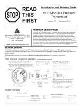
Standard Equipment
Figure 1 and Table 1 show standard equipment.
1
2
3
4
5
6
7
8
9
10
11
12
13
14
16
17
15
idj016.emf
Figure 1. Standard Equipment

729/729FC
Users Manual
4
Table 1. Standard Equipment
No. Equipment No. Equipment
729 or 729 FC Automatic Pressure Calibrator
Fitting, 1/8 in NPT-Female X M20-Female
AC/DC converter
Fitting, 1/4 in BSP-Female X 1/8 in NPT-Female
Mains line cable
Hanger Kit
Rechargeable Li-ion Battery
Hose to drain condensed water generated from
the Product. 1/8 in diameter, 1 ft length
Stackable test lead set
Hose for leakage test. 1/8 in diameter, 2 in
length
AC280 Sure Grip hook set (red and black)
Not
Shown
Adjustable quick-release strap for hanging the
Product
Alligator clips (red and black)
One set of TP220 test probes (red and black) Soft carrying case
USB communication cable: 3 ft (1 m) Type A
plug for host (PC) to Mini-B plug for device
Printed multilingual Safety Information
Nylon hose 1/8 in diameter, 3.5 ft length Traceable calibration report with data
Fitting, 1/8 in NPT-Female x 1/4 in NPT-
Female
PTFE Tape
Tube fitting, male connector (qty 2), 1/8 in
NPT male connector, 1/8 in hose
International AC Adapter Kit

Automatic Pressure Calibrator
Buttons
5
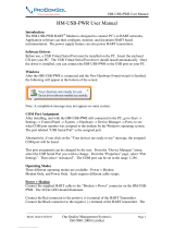
Buttons
See Figure 2 and Table 2 for the Product buttons and the softkeys.
4
13
9
8
12
11
10
7
6
5
3
2
1
18
16
15
14
17
idj001.emf
Figure 2. Buttons

729/729FC
Users Manual
6
Table 2. Buttons
Number Description Number Description
Power button. Push to turn on or turn off
the Product.
Display brightness button. Push to change the
display brightness from dim to bright and back again.
BACK button. Push to move to the
previous user interface (UI) screen. When
navigating through the screens, BACK can
move out of most screens and with
repeated pushes, can take you all the way
to the startup screen.
Numeric keypad. Used when a numeric entry is
necessary.
F1-F4 softkeys. Performs the specified
function of the label above each softkey on
the display. These labels change
throughout the UI.
ENTER button. Push to make a selection on the UI.
Only ENTER confirms numbers and characters.
Confirm all editable items with ENTER.
Arrow buttons. Push to move the display
cursor left, right, up, or down. Cursor
highlights in yellow over the selection.
CLEAR (ZERO) button. Push to clear highlighted
entry. When PI/PV/IP/SWT starts, push to zero the
pressure reading.
SELECT button. Push to make a selection
on the UI. This button cannot confirm
number or character choices (push
ENTER).
mA button. Push to select the mA measure function.

Automatic Pressure Calibrator
Buttons
7
Table 2. Buttons (cont.)
Number Description Number Description
VDC button. Push to select the measure dc
voltage function.
SOURCE PRESSURE button. Use this function
to output (source) a target pressure from the
Product. Use the arrows to select the Setpoint
field and enter the values with the number
buttons.
SETUP button. Push to enter the Setup menu
to change operating parameters. See Setup
Menu.
MEASURE PRESSURE button. Use this function
for pressure measurement mode.
TASKS button. Push to enter the Tasks menu.
See TASKS Menu.
HART button. Push to enter HART
communication mode.
VENT button. Push to release pressure at the
internal pressure port. VENTING shows on the
display as the Product vents. VENTED shows
after venting is complete.
HOLD button. Push to freeze the reading on the
display. Push it a second time to release the hold
on the display. Push and hold to capture the
screen and save into memory.

729/729FC
Users Manual
8
The Display
Figure 3 and Table 3 explain the display.
13
12
10
9
1
2 3 4 5 6
7
8
11
idj014.emf
Figure 3. The Display

Automatic Pressure Calibrator
The Display
9
Table 3. The Display
Number Description Number Description
Step size indicator Pressure units indicator
Setpoint indicator
External display shows selected device that is
connected. The device can be a pressure module,
temperature probe, process variable (PV) of
connected HART device, or Fluke Connect
secondary device reading.
Fluke Connect on indicator (729 FC only) Softkey indicator
HART on indicator Current, voltage, or pressure switch display
24 volt loop power active indicator Main display with measured or sourced value
Battery charge level Time and date display
Pressure port status

729/729FC
Users Manual
10
The display can also show different configurations:
Typically, the display does not show the third functions, see
Figure 4. See Triple-Function Display.
• The upper display for the internal pressure has these
different functions:
o VENT
o SOURCE
o MEASURE
• The lower display shows these different functions:
o Measure Current
o Source Current
o Simulate Current
o Measure VDC
o Switch
idj017.bmp
Figure 4. Typical Dual-Function Display

Automatic Pressure Calibrator
The Display
11
The screen has two sections:
The upper display shows the internal pressure controller
status and includes:
• Mode: Measure, Source, and Vent
• Pressure Value: Current measured pressure and unit
• Status: Shows nothing in measure mode, NOT READY,
STABLE in source mode, and VENTING, VENTED in
vent mode.
• Setpoint: Current setpoint for source function.
• Step Size: The step size when B (Step Up) and
C (Step Down) are pushed when sourcing
pressure.
The lower display shows the electrical status and includes:
• Mode: Measure Current, Source Current, Simulate
Current, Measure V dc, and Switch.
• Reading: Current reading from measure functions or
setpoint for source functions.
• Switch State: Shows the pressure reading when the
switch contacts open and close.
• Percent: Shows the percentage value of 4 mA to 20 mA
or 1 V to 5 V in measure functions.
• Status: Shows Open circuit detected in mA source
mode.

729/729FC
Users Manual
12
Triple-Function Display
When the third function (RTD, External Pressure
Module, HART Transmitter, or FC secondary device) is
connected, the Product changes to triple-function display
automatically. In the subsequent triple-function display,
the original bottom half of the display is divided into two
parts:
• The left display continues to show the electrical
measurement display.
• The right display shows the model name, reading,
and units from the selected third function. See
Figure 5. The figure shows a transmitter device
(3051C).
When more than one third function is available, use the
arrow keys to highlight the device (in yellow) in the right
display. Then use the softkeys to select the device to
show.
idj022.bmp
Figure 5. Triple-Function Display

Automatic Pressure Calibrator
The Display
13
RTD Connection
The display can show RTD temperature measurements in
the selected unit (C/F) as the third-function. When the
temperature unit field highlights, push the softkey to toggle
the temperature setting. The ohms reading shows.
Note
The Product supports PT100-385 RTD only.
Pressure Module Connection
The Product automatically detects external pressure module
installation or removal. Move the cursor to the unit type and
push E to configure the pressure-unit type (it can be
different from the pressure unit of internal pressure). Change
the unit type of the internal pressure to automatically change
the unit type of the pressure module.
Figure 6 shows a pressure module as the third function.
• When you plug in an external pressure module, the
pressure-unit type defaults to the internal pressure unit
type.
• When you remove or install an external pressure
module, the zero offset resets.
idj020.bmp
Figure 6. Triple-Function Display with External Pressure
Module Connected

729/729FC
Users Manual
14
Fluke Connect Device Connection
The display shows connected FC device measurements as
the third-function.
See Setup Menu for information to manage secondary FC
devices.
Page is loading ...
Page is loading ...
Page is loading ...
Page is loading ...
Page is loading ...
Page is loading ...
Page is loading ...
Page is loading ...
Page is loading ...
Page is loading ...
Page is loading ...
Page is loading ...
Page is loading ...
Page is loading ...
Page is loading ...
Page is loading ...
Page is loading ...
Page is loading ...
Page is loading ...
Page is loading ...
Page is loading ...
Page is loading ...
Page is loading ...
Page is loading ...
Page is loading ...
Page is loading ...
Page is loading ...
Page is loading ...
Page is loading ...
Page is loading ...
Page is loading ...
Page is loading ...
Page is loading ...
Page is loading ...
Page is loading ...
Page is loading ...
Page is loading ...
Page is loading ...
Page is loading ...
Page is loading ...
Page is loading ...
Page is loading ...
Page is loading ...
Page is loading ...
Page is loading ...
Page is loading ...
Page is loading ...
Page is loading ...
Page is loading ...
Page is loading ...
Page is loading ...
Page is loading ...
Page is loading ...
Page is loading ...
Page is loading ...
Page is loading ...
Page is loading ...
Page is loading ...
Page is loading ...
Page is loading ...
Page is loading ...
Page is loading ...
Page is loading ...
Page is loading ...
Page is loading ...
Page is loading ...
-
 1
1
-
 2
2
-
 3
3
-
 4
4
-
 5
5
-
 6
6
-
 7
7
-
 8
8
-
 9
9
-
 10
10
-
 11
11
-
 12
12
-
 13
13
-
 14
14
-
 15
15
-
 16
16
-
 17
17
-
 18
18
-
 19
19
-
 20
20
-
 21
21
-
 22
22
-
 23
23
-
 24
24
-
 25
25
-
 26
26
-
 27
27
-
 28
28
-
 29
29
-
 30
30
-
 31
31
-
 32
32
-
 33
33
-
 34
34
-
 35
35
-
 36
36
-
 37
37
-
 38
38
-
 39
39
-
 40
40
-
 41
41
-
 42
42
-
 43
43
-
 44
44
-
 45
45
-
 46
46
-
 47
47
-
 48
48
-
 49
49
-
 50
50
-
 51
51
-
 52
52
-
 53
53
-
 54
54
-
 55
55
-
 56
56
-
 57
57
-
 58
58
-
 59
59
-
 60
60
-
 61
61
-
 62
62
-
 63
63
-
 64
64
-
 65
65
-
 66
66
-
 67
67
-
 68
68
-
 69
69
-
 70
70
-
 71
71
-
 72
72
-
 73
73
-
 74
74
-
 75
75
-
 76
76
-
 77
77
-
 78
78
-
 79
79
-
 80
80
-
 81
81
-
 82
82
-
 83
83
-
 84
84
-
 85
85
-
 86
86


Fluke 729 automatisk trykkalibrator User manual
- Type
- User manual
- This manual is also suitable for
Ask a question and I''ll find the answer in the document
Finding information in a document is now easier with AI
Related papers
-
Fluke 729 Automatic Pressure Calibrator User manual
-
-
-
Fluke FL700-154 Quick start guide
-
-
Fluke 51 II Handheld Digital Probe Thermometer User manual
-
-
Fluke TL80A Owner's manual
-
-
Other documents
-
Omega PCL340 Owner's manual
-
-
-
Aktakom AM-7025 User manual
-
 ANDERSON-NEGELE MPP Installation And Startup Manual
-
 Hantek HT824 User manual
-
-
Dwyer Series 659 User manual
-
-
 ProComSol HM-USB-PWR User manual


