
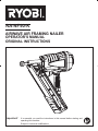
AIRWAVE AIR FRAMING NAILER
OPERATOR'S MANUAL
ORIGINAL INSTRUCTIONS
RA-NF90-K
Important! It is essential you read the instructions in this manual before starting and
operating this machine.
6XEMHFWWRWHFKQLFDOPRGL¿FDWLRQV

Fig. 5
Fig. 7Fig. 6
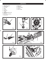
Fig. 1
Fig. 4
Fig. 2
Fig. 3
1
2
3
1
2
1
3
6
5
4
7
8
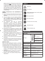
DESCRIPTION
1. Nitto style coupler
2. Exhaust cap
3. Air supply
4. Nails
5. Pusher
6. Magazine
7. Trigger
8. Depth adjustment knob
9. Stopper
10. Flat blade screwdriver
11. Safety yoke
12. Hex screw
13. Hex key
14. Screw hanger
15. Wrench
16. No-mar pad
16
11

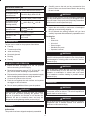
Quick
connector
Quick
connector
Lubricator Filter
Cut-off
valve
Regulator
(0-8.5 bar)
Quick
coupler
Tool
Air
compressor
Quick
coupler
Air hose
Fig. 8
Fig. 12
Fig. 11
Fig. 9
Fig. 13
1
2
5
13
4
12
6
10
Fig. 10
2
1
1
2
5
9
4
4
6
6
14
15
Fig. 14
11

1
GENERAL SAFETY RULES
Ŷ For multiple hazards, read and understand the safety
instructions before installing, operating, repairing,
maintaining, changing accessories on, or working
near, the air tool. Failure to do so can result in serious
bodily injury.
Ŷ Only qualified and trained operators should install,
adjust or use the air tool.
Ŷ Do not modify this air tool. Modifications can reduce
the effectiveness of safety measures and increase the
risks to the operator.
Ŷ Do not discard the safety instructions; give them to the
operator.
Ŷ Do not use the air tool if it has been damaged.
Ŷ Tools shall be inspected periodically to verify that the
ratings and markings required by this part of EN 792-
13 are legibly marked on the tool. The employer/user
shall contact the manufacturer to obtain replacement
marking labels when necessary.
PROJECTILE HAZARDS
Ŷ Be aware that the failure of the work piece, or
accessories, or even of the fastener driving tool itself,
can generate high-velocity projectiles.
Ŷ Always wear impact-resistant eye protection during
the operation of the air tool. The grade of protection
required should be assessed for each use.
Ŷ Ensure that the work piece is securely fixed.
ENTANGLEMENT HAZARDS
Choking, scalping and/or lacerations can occur if loose
clothing, personal jewellery, neck wear, hair or gloves are
not kept away from the tool and accessories.
OPERATING HAZARDS
Ŷ Operators and maintenance personnel shall be
physically able to handle the bulk, weight and power
of the tool.
Ŷ Hold the tool correctly; be ready to counteract normal
or sudden movements and have both hands available.
Ŷ Maintain a balanced body position and secure footing.
Ŷ Release the start-and-stop device in the case of an
interruption of the compressed air supply.
Ŷ Use only lubricants recommended by the manufacturer.
Ŷ Personal protective safety glasses shall be used; suitable
gloves and protective clothing are recommended.
REPETITIVE MOTIONS HAZARDS
Ŷ When using an air tool to perform work-related
activities, the operator can experience discomfort in
the hands, arms, shoulders, neck or other parts of the
body.
Ŷ While using an air tool, the operator should adopt a
comfortable posture while maintaining a secure footing
and avoiding awkward or off-balanced postures. The
operator should change posture during extended
tasks, which can help avoid discomfort and fatigue.
Ŷ If the operator experiences symptoms, such as
persistent or recurring discomfort, pain, throbbing,
aching, tingling, numbness, burning sensations or
stiffness, these warning signs should not be ignored.
The operator should tell the employer and consult a
qualified health professional.
ACCESSORY HAZARDS
Ŷ Disconnect the air tool from the compressed air line
before fitting or changing the fasteners or accessory.
Ŷ Use only sizes and types of accessories and
consumables that are recommended by the air tool
manufacturer; do not use other types or sizes of
accessories and consumables.
WORKPLACE HAZARDS
Ŷ Slips, trips and falls are major causes of workplace
injury. Be aware of slippery surfaces caused by the
use of the tool and also of trip hazards caused by the
air line.
Ŷ Proceed with care in unfamiliar surroundings. There
can be hidden hazards, such as electricity or other
utility lines.
Ŷ The air tool is not intended for use in potentially
explosive atmospheres and is not insulated against
coming into contact with electric power.
Ŷ Ensure that there are no electrical cables, gas pipes,
etc., that can cause a hazard if damaged by use of
the tool.
NOISE EMISSION
The characteristic noise values for the fastener driving tool
have been determined in accordance with EN12549:1999
and EN ISO4871 "Acoustics-Noise test code for fastener
GULYLQJWRROV(QJLQHHULQJPHWKRGVHH6SHFL¿FDWLRQV
These values are tool-related characteristic values and do
not represent the noise development at the point of use.
Noise development at the point of use will for example
depend on the working environment, the work piece, the
work piece support, the number of driving operations, etc.
Depending in the conditions at the workplace and the form
of the workplace, individual noise attenuation measures
may need to be carried out, such as placing work pieces
on sound-damping supports, preventing work piece
vibration by means of clamping or covering, adjusting
to the minimum air pressure required for the operation
involved, etc.
In special cases it is necessary to wear hearing protection
equipment.
INFORMATION ON MECHANICAL IMPACT(VIBRATION)
The characteristic vibration values for the fastener driving
tool have been determined in accordance with ISO 8662-
11:1999 and EN 12096 – Measurement of vibration in

2
hand-held power tools – Part 11: Fastener driving tools
VHH6SHFL¿FDWLRQV
This value is a tool-related characteristic value and does
QRWUHSUHVHQWWKHLQÀXHQFHWRWKHKDQGDUPV\VWHPZKHQ
XVLQJWKHWRRO$QLQÀXHQFHWRWKHKDQGDUPV\VWHPZKHQ
using the tool will for example depend on the gripping
force, the contact pressure force, the working direction,
the adjustment of compressed air supply, the workplace
and the work piece support.
ADDITIONAL SAFETY INSTRUCTIONS FOR
PNEUMATIC POWER TOOLS
Ŷ Air under pressure can cause severe injury.
Ŷ Always shut off air supply, drain hose of air pressure
and disconnect tool from air supply whenever not in
use, before changing accessories or where making
repairs.
Ŷ Never direct air at yourself or anyone else.
Ŷ Whipping hoses can cause severe injury. Always
check for damaged or loose hoses and fittings.
Ŷ Cold air should be directed away from the hands.
Ŷ :KHQHYHU XQLYHUVDO WZLVW FRXSOLQJV FODZ FRXSOLQJV
are used, lock pins shall be installed and whip check
safety cables shall be used to safeguard against
possible hose-to-tool and hose-to-hose connection
failure.
Ŷ Do not exceed the maximum air pressure stated on
the tool.
Ŷ Never carry an air tool by the hose.
Ŷ Only fasteners listed in the specifications may be used
in the fastener driving tool. The fastener driving tool
and the fasteners specified in the specifications are to
be considered as one unit safety system.
Ŷ Quick action couplings shall be used for connection
to the compressed air system and the non-sealable
nipple must be fitted at the tool in such a way that no
compressed air remains in the tool after disconnection.
Ŷ Oxygen or combustible gases shall not be used as an
energy source for compressed air operated fastener
driving tools.
Ŷ Fastener driving tools shall only be connected to an
air supply where the maximum allowable pressure of
the tool cannot be exceeded by more than 10%; in the
case of higher pressure ,a pressure reducing valve
which includes a downstream safety valve shall be
built into the compressed air supply.
Ŷ Only the main energy and the lubricants listed in
the operating instructions may be used for the
maintenance of fastener driving tools. Only spare
parts specified by the manufacturer or his authorised
representative shall be used.
Ŷ Repairs shall be carried out only by the manufacturer's
authorized agents or by other experts, having due
regard to the information given in the operating
instructions.
Ŷ Stands for mounting the fastener driving tools to a
support, for example to a work table, shall be designed
and constructed by the stand manufacturer in such
a way that the fastener driving tools can be safely
fixed for the intended use, thus for example avoiding
damage, distortion and displacement.
Ŷ Check prior to each operation that the safety and
triggering mechanism is functioning properly and that
all nuts and bolts are right.
Ŷ Do not carry out any alterations to the fastener driving
tool.
Ŷ Do not disassemble or make inoperative any parts of
the fastener driving tool such as the safety yoke.
Ŷ Do not perform any “emergency repairs” without
proper tools and equipment.
Ŷ The fastener driving tool should be serviced properly
and at regular intervals in accordance with the
manufacturer’s instructions.
Ŷ Avoid weakening or damaging the tool, for example
by:
– punching or engraving;
– modification not authorized by the manufacturer;
– guiding against templates made of hard material
such as steel;
– dropping or pushing across the floor;
– using the tool as a hammer;
– applying excessive force of any kind.
Ŷ
Never point any fastener driving tool at yourself or at
any other person or animal.
Ŷ Hold the fastener driving tool during the work operation
in such a way that no injuries can be caused to the
head or to the body in the event of possible recoil
consequent upon a disruption in the compressed air
supply or hard areas within the workplace.
Ŷ Never actuate the fastener driving tool into free space.
This will avoid any hazard caused by free flying
fasteners and excessive strain of the tool.
Ŷ The tool shall be disconnected from the compressed
air system for the purpose of transportation, especially
where ladders are used or where an unusual physical
posture is adopted whilst moving .
Ŷ Carry the fastener driving tool at the workplace using
only the handle, and never with the trigger actuated.
Ŷ Take conditions at the workplace into account.
Fasteners can penetrate thin work pieces or slip off
corners and edges of workplaces, and thus put people
at risk.
Ŷ For personal safety, use protective equipment such ad
hearing and eye protection.
Ŷ Fastener driving tools are operated by actuating the
trigger using finger pressure.
In addition, fastener driving tool is fitted with a safety
yoke which enables the driving operation to be carried
out only after the safety yoke of the tool is pressed

3
against a work piece, These tools are marked with an
inverted triangle
behind the serial number and are
not permitted for use without an effective safety yoke.
A safety yoke is not required on fastener driving tools
which accelerate the heaviest usable fasteners to a
free flight velocity below an admissible risk of injury.
Those fastener driving tools are not marked with an
inverted triangle.
SAFETY INSTRUCTIONS FOR COMPRESSED AIR
SYSTEM
Ŷ Proper functioning of the fastener driving tool requires
filtered, dry and lubricated compressed air in adequate
quantities.
Ŷ If the air pressure in the line system exceeds the
maximum allowable pressure of the fastener driving
tool, a pressure reducing valve followed by a
downstream safety valve shall additionally be fitted in
the supply line to the tool.
Ŷ The compressor plant shall be adequately
dimensioned in terms of pressure output and
SHUIRUPDQFH YROXPHWULF IORZ IRU WKH FRQVXPSWLRQ
which is to be expected. Line sections which are too
small in relation to the length of the line (pipes and
KRVHV DV ZHOO DV RYHUORDGLQJ WKH FRPSUHVVRU ZLOO
result in pressure drops.
Ŷ Permanently laid compressed air pipelines should
have an internal diameter of at least 19 mm and a
corresponding large diameter where relatively long
pipelines or multiple users are involved.
Ŷ Compressed air pipelines should be laid so as to
form a gradient (highest point in the direction to the
FRPSUHVVRU (DVLO\ DFFHVVLEOH ZDWHU VHSDUDWRUV
should be installed at the lowest points.
Ŷ Junctions for users should be joined to the pipelines
from above,
Ŷ Connecting points for fastener driving tools should be
fitted with a compressed air servicing unit (filter/water
VHSDUDWRURLOHUGLUHFWO\DWWKHMXQFWLRQSRLQW
RESIDUAL RISKS
Even if you are operating this product in accordance
with all the safety requirements, potential risks of injury
and damage remain. The following dangers can arise in
connection with the structure and design of this product:
1. Health defects resulting from vibration and noise
emission if the product is being used over long periods
of time or not adequately managed and properly
maintained.
2. Injuries and damage to property due to fasteners or
the sudden impact of hidden objects during use.
3. Danger of injury and property damage caused by
À\LQJREMHFWV
SYMBOLS
Safety alert
CE conformity
Please read the instructions carefully before
starting the product.
Wear eye protection.
Wear ear protection.
Lubricate with air tool oil daily.
Keep hands away
Tacker with safety yoke
SPECIFICATIONS
FASTENER
Nail type
Clipped head framing
nails
2.87 – 3.33 mm
Nail range: 50 - 90 mm
Collation angle: 34°
TOOL
Magazine capacity
70 nails
Air inlet size
PP´
Air hose size
PP´
Air consumption
/F\FOHDWEDUSVL
Working pressure
range
EDUSVL
Exhaust 5HDUDGMXVWDEOH
Tool weight
QRQDLOV
3.78 kg

4
NOISE AND VIBRATION
Noise according to EN 12549:1999 and EN ISO 4871
A-weighted sound
pressure level
L
PA
G%$.
PA
=2.5 dB
Sound power level L
WA
G%$.
WA
=2.5 dB
A-weighted sound
pressure level(at
ZRUNLQJVWDWLRQ
L
PA
G%$.
PA
=2.5 dB
C-weighted sound
pressure level
L
PC,peak
G%$
K
PC,peak
=2.5 dB
Vibration according to ISO 8662-11:1999
Vibration in the
handle
ah,W=13.4 m/s
2
,
K=1.5 m/s
2
INTENDED USE
The tool can be used for the purposes listed below:
Ŷ Framing
Ŷ 7UXVVHVDQGURR¿QJ
Ŷ -RLVWVDQGÀRRULQJ
Ŷ Structural plywood
Ŷ Decking
Ŷ Fencing
AIR SUPPLY AND OPERATION
Ŷ (QVXUH DLU YDOYH RU WULJJHU LV LQ WKH ³RII´ SRVLWLRQ
before connecting to the air supply.
Ŷ Required air pressure range of 5.5 - 8.3 bar (80 - 120
SVLDQGDQDLUIORZDFFRUGLQJWRVSHFLILFDWLRQV
Ŷ Disconnect the product from the compressed air supply
before changing accessories or making adjustments.
Ŷ Connect the product to the air hose.
Ŷ Push the tool against the work surface and squeeze
the trigger to drive a fastener.
Ŷ Do not use any additional force upon the product.
WARNING
Ensure the air supply is clean and does not exceed
EDU SVL ZKLOH RSHUDWLQJ WKH SURGXFW 7RR
high an air pressure and unclean air will shorten the
product's life due to excessive wear, and may be
dangerous causing damage and/or personal injury.
ASSEMBLY
UNPACKING
This product has been shipped completely assembled.
Ŷ Carefully remove the tool and any accessories from
the box. Make sure that all items listed in the packing
list are included.
WARNING
Do not use this product if it is not completely assembled
or if any parts appear to be missing or damaged. Use of
a product that is not properly and completely assembled
could result in serious personal injury.
Ŷ Inspect the tool carefully to make sure no breakage or
damage occurred during shipping.
Ŷ Do not discard the packing material until you have
carefully inspected and satisfactorily operated the tool.
Packing list
– Nailer
– Wrench kit
– Air tool oil
– Screw hanger
– Moulded carry case
– Operator’s manual
WARNING
If any parts are damaged or missing do not operate
this tool until the parts are replaced. Use of this product
with damaged or missing parts could result in serious
personal injury.
WARNING
Do not attempt to modify this tool or create accessories
not recommended for use with this tool. Any such
DOWHUDWLRQ RU PRGL¿FDWLRQ LV PLVXVH DQG FRXOG UHVXOW
in a hazardous condition leading to possible serious
personal injury.
OPERATION
WARNING
Do not use oxygen, combustible gases or bottled gases
as a power source for this tool. The tool will explode and
cause death or serious injury.
WARNING
Do not allow familiarity with tools to make you careless.
Remember that a careless fraction of a second is
VXI¿FLHQWWRLQÀLFWVHYHUHLQMXU\

5
WARNING
Always wear safety goggles or safety glasses with side
shields when operating tools. Failure to do so could
result in objects being thrown into your eyes resulting
in possible serious injury.
WARNING
Disconnect the tool from the air supply before leaving
the work area, moving the tool to another location, or
handing the tool to another person. Failure to do so
could result in serious personal injury.
WARNING
Always wear eye protection. Eye protection does
QRW ¿W DOO RSHUDWRUV LQ WKH VDPH ZD\ 0DNH VXUH WKH
eye protection chosen has side shields or provides
SURWHFWLRQ IURP À\LQJ GHEULV ERWK IURP WKH IURQW DQG
sides.
PREPARING THE TOOL FOR USE
6HH¿JXUH
WARNING
Please read and observe these operating instructions
before using the tool. Basic safety measures should
always be strictly followed to protect against damage to
the equipment and personal injury to the user or other
people working in the vicinity of operation.
Under normal use conditions, the tool should be lubricated
with air tool oil before connecting the tool to an air supply.
$GG DLU WRROOXEULFDQW LQWR WKH DLU ¿WWLQJ RQ WKH WRRO RQFH
daily with minimal use, or twice a day with heavy use. Only
a few drops of oil at a time is necessary. Too much oil will
only collect inside the tool and will be noticeable in the
exhaust cycle.
Before connecting the tool, check the air compressor
gauge to be sure it is functioning within the proper range
RIEDUSVL
NO-MAR PAD
6HH¿JXUH
The no-mar pad attached to the safety yoke of the tool
helps prevent marring and denting when working with
softer woods.
WARNING
Disconnect the tool from the air supply before removing
or replacing the no-mar pad. Failure to do so could
result in serious personal injury.
The pad can be removed by pulling it down and away from
WKHVDIHW\\RNH7RUHSODFHWKHSDG¿WLWLQWRSODFHRYHU
the safety yoke and push up.
ADJUSTING THE EXHAUST
6HH¿JXUH
The adjustable exhaust on the end cap of the tool allows
the operator to direct the exhaust according to operator
preference.
To adjust, turn the exhaust cap in the desired direction.
CONNECTING THE TOOL TO AN AIR SUPPLY
6HH¿JXUH
WARNING
Ensure that the pressure supplied by the compressed
air system does not exceed the maximum allowable
pressure of the fastener driving tool. Set the air
pressure initially to the lower value of the recommended
DOORZDEOHSUHVVXUHVHH6SHFL¿FDWLRQV
WARNING
Empty the magazine to prevent a fastener from being
ejected at the next stage of work in the event that
internal parts of the fastener driving tool are not in the
starting position following maintenance and repair work
or transportation.
WARNING
Connect the fastener driving tool to the compressed
air supply using suitable pressure hose equipped with
quick-action connectors.
WARNING
Check for proper functioning by applying the safety yoke
of the fastener driving tool to a piece of wood or wooden
material and actuating the trigger once or twice.
This tool is designed to operate on clean, dry compressed
air at regulated pressures between 5.5 - 8.3 bar (80 - 120
SVL7KHFRUUHFWDLUSUHVVXUHLVWKHORZHVWSUHVVXUHWKDW
will do the job.
NOTE:$LUSUHVVXUHWKDWLVKLJKHUWKDQEDUSVL
may damage the tool.
The tool and air hose must have a hose coupling that
allows all pressure to be removed from the tool when the
coupling is disconnected.

6
WARNING
Always use a coupling that discharges all the
FRPSUHVVHG DLU LQ WKH WRRO DW WKH WLPH WKH ¿WWLQJ RU
hose coupling is disconnected. Using a coupling that
does not discharge the compressed air could cause
unintended operation and serious personal injury.
WARNING
Do not climb rigging or scaffolding while carrying a tool
that is connected to an air hose. Doing so could result
in serious personal injury.
Connect the tool to the air supply with a 1/4 in. female
quick connector. For maximum tool performance, a 3/8 in.
VXSSO\OLQHDQG¿WWLQJVDUHUHTXLUHG
LOADING THE TOOL WITH FASTENERS
6HH¿JXUH
WARNING
2QO\ WKRVH IDVWHQHUV VSHFL¿HG XQGHU 6SHFL¿FDWLRQV
PD\ EH XVHG :KHQ ¿OOLQJ WKH PDJD]LQH KROG WKH
tool so that the safety yoke is not pointing towards the
operator or any other person or animals.
WARNING
The tool’s driving mechanism may cycle when the tool
LV¿UVWFRQQHFWHGWRWKHDLUVXSSO\$OZD\VFRQQHFWWKH
tool to a pressurized air supply before loading fasteners
to prevent injury from unintended cycling. Always make
sure the tool’s magazine is empty at the beginning of
each work session, before connecting to an air supply.
1. Connect the tool to the air supply.
2. With the safety yoke of the tool pointed away from you,
feed a strip of fasteners into the magazine. Be sure
the fasteners are pointed downward and at the angle
shown.
3. Slide the pusher all the way to the rear of the magazine.
WARNING
Keep the tool pointed away from yourself and others
when loading fasteners. Failure to do so could result in
possible serious personal injury.
4. Release the pusher and allow it to push the fasteners
to the driving mechanism. The pusher will stop when it
rests against the end of the fastener strip.
NOTE: Do not allow the pusher to snap back into place.
WARNING
Use only the fasteners recommended for use with this
tool. The use of any other fasteners can result in tool
malfunction, leading to serious injuries.
WARNING
Never load fasteners with the safety yoke or trigger
activated. Doing so could result in possible serious
personal injury.
WARNING
Do not use fasteners with shank diameter smaller than
2.87 mm. Doing so may cause fasteners to exit the
tool prematurely through the guide track. Do not use
hardened fasteners with pneumatic tools. This could
lead to excessive wear of the guide body and allow
fasteners to exit the back of the guide body, leading to
serious personal injury.
DRIVING A FASTENER
6HH¿JXUH
WARNING
Check the safety yoke before use. If it is deformed or
cannot telescope, do not use the tool until it is replaced.
Operate with a deformed safety yoke could result in
serious personal injury.
WARNING
Never wedge or hold back the safety yoke mechanism
during operation of the tool. Doing so could result in
possible serious injury.
Avoid triggering the fastener driving tool if the magazine
is empty.
Any defective or improperly functioning fastener driving tool
must immediately be disconnected from the compressed
air supply and passed to a specialist for inspection.
In the event of longer breaks in work or at the end of the
working shift, disconnect the tool from the compressed air
supply and it is recommended to empty the magazine.
The compressed air connectors of the fastener driving tool
and the hoses should be protected against contamination,
the ingress of coarse dust chips, sand, etc, will result in
leaks and damage to the fastener driving tool and the
couplings.
Single sequential actuation mode
The tool employs single sequential actuation mode.
1. Connect the tool to the air supply.

7
2. *ULS WKH WRRO ¿UPO\ WR PDLQWDLQ FRQWURO 3RVLWLRQ WKH
safety yoke of the tool onto the work surface.
3. Push the tool against the work surface to depress the
safety yoke.
4. Squeeze the trigger to drive a fastener.
5. Allow the tool to recoil away from the work surface as
the fastener is driven.
6. $OZD\V UHPRYH \RXU ¿QJHU IURP WKH WULJJHU DIWHU WKH
fastener has been driven.
NOTE: If there is only one nail left in the magazine, it may
not be fully driven into the workpiece, may be bent or fall
out.
WARNING
During normal use the tool will recoil immediately
after driving a fastener. This is a normal function of
the tool. Do not attempt to prevent the recoil by holding
the tool against the work. Restriction to the recoil can
result in a second fastener being driven from the tool.
*ULSWKHKDQGOH¿UPO\OHWWKHWRROGRWKHZRUNDQGGR
not place second hand on top of tool or near exhaust
at any time. Failure to heed this warning can result in
serious personal injury.
SETTING THE AIR PRESSURE
Having checked that the fastener driving tool is functioning
correctly, apply the tool to a work piece and actuate the
trigger.
Check whether the fastener has been driven into the work
piece in accordance with the requirements.
Ɣ If the fastener is protruding, increase the air
pressure in increments of 0.5 bar, checking the
result after each new adjustment;
Ɣ If the fastener is driven into an excessive depth,
reduce the air pressure in increments of 0.5 bar
until the result is satisfactory.
Ɣ It is preferred to adjust the depth adjustment knob
to reach the good fastening effect.
Work with the lowest possible air pressure. This will give
\RXWKUHHVLJQL¿FDQWDGYDQWDJHV
1. Energy will be saved,
2. Less noise will be produced,
3. A reduction in fastener driving tool wear will be
achieved.
The amount of air pressure required will depend on the
size of the fastener and the workpiece material.
Begin testing the depth of drive by driving a test fastener
into the same type of workpiece material used for the
actual job.
Drive a test fastener with the air pressure set at 6.2 - 6.5
EDUSVL5DLVHRUORZHUWKHDLU SUHVVXUH WR ¿QG
the lowest setting that will perform the job with consistent
results.
It may be possible to achieve the desired depth with air
SUHVVXUH DGMXVWPHQWV DORQH ,I ¿QHU DGMXVWPHQWV DUH
needed, use the drive depth adjustment on the tool.
DRIVE DEPTH ADJUSTMENT
6HH¿JXUH
The driving depth of the fastener may be adjusted. It
is advisable to test the depth on a scrap workpiece to
determine the required depth for the application.
7RGHWHUPLQHGHSWKRIGULYH ¿UVW DGMXVW WKH DLU SUHVVXUH
and drive a test fastener. To achieve the desired depth,
use the drive depth adjustment on the tool.
1. Disconnect the tool from the air supply.
2. Turn the depth adjustment knob left or right to change
the driving depth.
3. Reconnect the tool to the air supply.
4. Drive a test fastener after each adjustment until the
desired depth is set.
REMOVING FASTENERS FROM THE TOOL
6HH¿JXUH
1. Disconnect the tool from the air supply.
WARNING
Disconnect the tool from the air supply before
performing maintenance. Failure to do so could result
in serious personal injury.
2. To remove a strip of fasteners from the tool, retract the
pusher until it reaches the end of the magazine.
NOTE: $OZD\V NHHS ¿QJHUV FOHDU RI IDVWHQHU WUDFN RI
magazine to prevent injury from unintended release of the
pusher.
3. Tilt the tool up so that the hose connector faces down.
Press the pusher button and slowly release the pusher
to the front of the magazine. The strip of fasteners will
slide back until it reaches the stopper.
4. Press the stopper and let the fasteners exit the rear of
the magazine.
CLEARING A JAMMED FASTENER
6HH¿JXUH
WARNING
Disconnect the tool from the air supply before clearing a
jammed fastener. Failure to do so could result in serious
personal injury.
If a fastener becomes jammed in the tool, disconnect the
air hose and keep the tool pointed away from you while
clearing the jam.
1. Disconnect the tool from the air supply.
2. Remove fasteners from the tool.
3. ,QVHUW D ÀDW EODGH VFUHZGULYHU LQWR WKH GULYLQJ
mechanism and push the driver mechanism back,
freeing the fastener jam.

8
4. Remove the jammed fastener.
5. Reconnect the tool to the air supply.
6. Reinstall fasteners.
ATTACHING THE SCREW HANGER
6HH¿JXUH
1. Using a hex key, remove the hex screw at the exhaust
cap.
2. Apply a little screw glue on the screw thread of the
screw hanger.
3. Attach the screw hanger at the exhaust cap. Tighten
the screw hanger using a wrench. (Tightening torque
UDQJH1P
MAINTENANCE
WARNING
When servicing use only identical replacement parts.
Use of any other parts may create a hazard or cause
product damage.
WARNING
Always wear eye protection with side shields marked to
comply with one of the following standards:
Ɣ Australian Standard – AS/NZS 1337
Ɣ European Standard – CE EN166
Ɣ American Standard – ANSI Z87.1
Failure to do so could result in objects being thrown into
your eyes resulting in possible serious injury.
WARNING
Disconnect the tool from the air supply and empty the
magazine before performing maintenance. Failure to do
so could result in serious personal injury.
GENERAL MAINTENANCE
Avoid using solvents when cleaning plastic parts. Most
plastics are susceptible to damage from various types of
commercial solvents and may be damaged by their use.
Use clean cloths to remove dirt, dust, oil, grease, etc.
WARNING
'RQRWDWDQ\WLPHOHWEUDNHÀXLGVJDVROLQHSHWUROHXP
based products, penetrating oils, etc., come in contact
with plastic parts. Chemicals can damage, weaken or
destroy plastic which may result in serious personal
injury.
COLD WEATHER OPERATION
For cold weather operation, near and below freezing,
the moisture in the air line may freeze and prevent tool
operation. We recommend the use of air tool lubricant or
SHUPDQHQWDQWLIUHH]HHWK\OHQHJO\FRODVDFROGZHDWKHU
lubricant.
WARNING
Do not store tools in a cold weather environment to
prevent frost or ice formation on the tools’ operating
valves and mechanisms that could cause tool failure.
NOTE: Some commercial air line drying liquids are harmful
to “O” rings and seals. Do not use these low temperature
air dryers without checking compatibility.
AIR SUPPLY PRESSURE AND VOLUME
Air volume is as important as air pressure. The air volume
supplied to the tool may be inadequate because of
XQGHUVL]H¿WWLQJVDQGKRVHVRUIURPWKHHIIHFWVRIGLUWDQG
ZDWHULQWKHV\VWHP5HVWULFWHGDLUÀRZZLOOSUHYHQWWKHWRRO
from receiving an adequate volume of air, even though
the pressure reading is high. The results will be a slow
operation or reduced driving power. Before evaluating tool
problems for these symptoms, trace the air supply from
the tool to the supply source for restrictive connectors,
low points containing water and anything else that would
SUHYHQWIXOOYROXPHÀRZRIDLUWRWKHWRRO
REQUIRED DAILY CHECKLIST
1. Disconnect the air supply from the tool and remove
all fasteners.
2. Check all screws, nuts, bolts, and pins on the tool. If
any of these are loose, they must be tightened with the
appropriate size wrench.
3. Press the safety yoke against a workpiece to ensure
that it moves smoothly.
4. With the safety yoke depressed, pull the trigger. The
trigger should move smoothly, without binding.
5. While the tool is not loaded, connect the appropriate
DLUVXSSO\DWEDUSVLWRWKHWRRO
Ɣ Without pulling the trigger, press the safety yoke
against a workpiece several times. The tool must
not operate.
Ɣ With the safety yoke not engaged on the workpiece,
point the tool down and away from you and other
persons, and pull the trigger several times. Hold
the trigger in this position for a minimum of 5
seconds. The tool must not operate.
Ɣ Press the safety yoke firmly against the workpiece,
and pull the trigger. The tool must operate.
Ɣ With the safety yoke still depressed, release the
trigger. The driver must return to its up position.
6. If the tool successfully meets all the requirements
in this checklist, it is ready for use. Load the proper
fasteners for the desired application.
7. Set the depth of drive according to the “drive depth
adjustment” section in this manual. Repeat this
checklist before using the tool each day, or if the tool is
dropped or damaged in any way.

9
WARNING
Do not use any attachments or accessories not
recommended by the manufacturer of this tool. The use
of attachments or accessories not recommended can
result in serious personal injury.
LUBRICATION
$Q DXWRPDWLF LQOLQH ¿OWHUUHJXODWRUOXEULFDWRU LV
UHFRPPHQGHG)LJDVLWLQFUHDVHVSURGXFWOLIHDQGNHHSV
the product in sustained operation. The in-line lubricator
VKRXOGEHUHJXODUO\FKHFNHGDQG¿OOHGZLWKDLUWRRORLO
Proper adjustment of the in-line lubricator is performed by
placing a sheet of paper next to the exhaust ports and
actuate the tool 10 - 15 times without fasteners loaded.
The lubricator is properly set when a light stain of oil
collects on the paper. Excessive amounts of oil should be
avoided.
If it becomes necessary to store the product for an extended
SHULRGRIWLPHRYHUQLJKWZHHNHQGHWFLWVKRXOGUHFHLYH
a generous amount of lubrication at that time. Actuate the
tool 10 - 15 times without fasteners loaded to ensure oil
has been evenly distributed throughout the product. The
product should be stored in a clean and dry environment.
Ɣ It is most important that the product be properly
lubricated by keeping the air line lubricator filled
and correctly adjusted. Without proper lubrication
the product will not work properly and parts will
wear prematurely.
Use correct lubricant in the air line lubricator. The
lubricator should be of low air flow or changing air flow
type, and should be kept filled to the correct level. Use only
recommended lubricants, specially made for pneumatic
applications. Substitutes may harm the rubber compounds
in the product's O-rings and other rubber parts.
IMPORTANT!
6HH¿JXUH
,I D ¿OWHUUHJXODWRUOXEULFDWRU LV QRW LQVWDOOHG RQ WKH DLU
system, air operated tools should be lubricated at least
once a day or after 2 hours of work with 2 - 6 drops
of oil, depending on the work environment, directly
WKURXJKWKHPDOH¿WWLQJLQWKHWRROKRXVLQJ
20140515v1

10
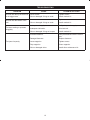
TROUBLESHOOTING
PROBLEM CAUSE POSSIBLE SOLUTION
Air leak near the top of the tool or
in the trigger area.
Loose screws. Tighten screws.
Worn or damaged O-rings or seals. Install overhaul kit.
Air leak near the bottom of the
tool.
Loose screws. Tighten screws.
Worn or damaged O-rings or seals. Install overhaul kit.
Tool does nothing or operates
sluggishly.
Inadequate air supply. Verify adequate air supply.
Inadequate lubrication. Lubricate tool.
Worn or damaged O-rings or bumper. Install overhaul kit.
Tool jams frequently.
Incorrect fasteners. Verify that fasteners are the correct
size.
Damaged fasteners. Replace fasteners.
Loose magazine. Tighten screws.
Dirty magazine. Clean magazine.
Worn or damaged driver. Install driver maintenance kit.

11
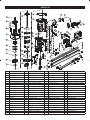
PARTS LIST
No. Description No. Description No. Description No. Description
1 Bolt 23 Gun body 45 Adjustment rod 67 Locknut M6
2 $LUGHÀHFWRU 24 O-ring 62 x 1.8 46 Adjustment bolt M6 68 Pusher seat
3 'HÀHFWRUSLHFH 25 Drive guide 47 Adjustment nut M6 69 Pusher spring
4 Pin 26 Spring washer D8 48 Roll pin 3 x 20 70 Pusher
5 Spring 27 Hex socket bolt M8 x 25 49 Roll pin 2.5 X 22 71 Orientation block
6 Hex socket bolt M6 x 30 28 Left orientation rubber 50 Roll pin 2.5 X 18 72 Magazine protection mantle
7 Cylinder cover 29 Right orientation rubber 51 Safety plate 73 Roll pin C4 x 18
8 Cylinder cover bumper 30 Switch seat sealing ring 52 Trigger 74 Spring core
9 Compressed spring 31 Valve seat 53 Oriented pin 75 Coil spring
10 O-ring 48.7 X 2.65 32 O-ring 16 x 1.6 54 O-ring 1.7 X 2 76 Fixed seat
11 O-ring 63 x 2.65 33 Valve sleeve 55 Safety stand 77 +H[QXWZLWKÀDQJH0
12 Head valve 34 O-ring 6.1 X 1.8 56 C ring D=3 78 Hex socket bolt M6 x 20
13 O-ring 50 x 3.55 35 O-ring 6.4 X 2 57 Safety stand shield 79 Hand protecting cushion
14 Piston 36 O-ring 9 x 1.8 58 Driver guide shield 80 Handle sleeve
15 O-ring 67 x 2.65 37 Switch spring 59 Drive bolt 81 End cap washer
16 Cylinder sealing ring 38 Switch stem 60 Coil spring pin 82 End cap
17 Cylinder 39 O-ring 2.4 X 1.6 61 Air inlet plug cover 83 Hex socket bolt M5 x 16
18 Sealing ring 40 O-ring 18 x 2.65 62 Magazine 84 Air inlet plug
19 O-ring 95 x 2.65 41 Switch seat 63 Drive nail bar 85 Compress spring
20 Collar 42 Adjustment seat 64 Hex bolt M6 x 10 86 Hex socket screw M6 x 16
21 Bumper 43 Safety yoke spring 65 Hex socket bolt M3 x 10 87 Orientation bar
22 Gasket 44 Adjustment bolt washer 66 Hex socket bolt M6 x 12

Techtronic Industries (Australia) Pty. Ltd.
Level 1, 660 Doncaster Road
Doncaster, VIC 3108, Australia
Techtronic Industries New Zealand Ltd.
18-26 Amelia Earhart Avenue
Mangere, Auckland 2022, New Zealand
-
 1
1
-
 2
2
-
 3
3
-
 4
4
-
 5
5
-
 6
6
-
 7
7
-
 8
8
-
 9
9
-
 10
10
-
 11
11
-
 12
12
-
 13
13
-
 14
14
-
 15
15


Ask a question and I''ll find the answer in the document
Finding information in a document is now easier with AI
Other documents
-
Husky H4340 Installation guide
-
RIDGID R250SFA User manual
-
-
-
 FASCO 11677F User manual
-
Parkside PDSS 310 A3 Operation and Safety Notes
-
Milwaukee M18CN15GA-0C User manual
-
Powermate CHFN35P Installation guide
-
Powerplus POWAIR0312 Owner's manual
-
Senco HN150 User manual
