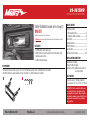
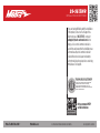
Metra Electronics 99-9613WR is a comprehensive kit designed to facilitate the installation of an aftermarket radio in Harley-Davidson FL models with a fairing, produced between 1998 and 2013, excluding those with a factory amplifier or more than two speakers.
Metra Electronics 99-9613WR is a comprehensive kit designed to facilitate the installation of an aftermarket radio in Harley-Davidson FL models with a fairing, produced between 1998 and 2013, excluding those with a factory amplifier or more than two speakers.


-
 1
1
-
 2
2
-
 3
3
-
 4
4
-
 5
5
-
 6
6
-
 7
7
-
 8
8
-
 9
9
-
 10
10
-
 11
11
-
 12
12


Metra Electronics 99-9613WR is a comprehensive kit designed to facilitate the installation of an aftermarket radio in Harley-Davidson FL models with a fairing, produced between 1998 and 2013, excluding those with a factory amplifier or more than two speakers.
Ask a question and I''ll find the answer in the document
Finding information in a document is now easier with AI
Related papers
-
Metra 99-7387HG Installation guide
-
-
-
-
-
-
-
Metra 107-GM5B Operating instructions
-
Metra 99-5841B User manual
-
Metra 99-9014HG Owner's manual
Other documents
-
Axxess ASWC-1 Operating instructions
-
Planet Audio PNV9680 Owner's manual
-
-
Axxess AX-TYAMP1-SWC Installation Instructions Manual
-
-
Axxess AX-LR90092 Installation guide
-
-
-
-