3
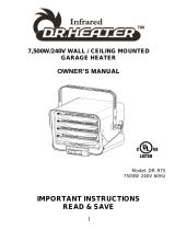
IMPORTANT INSTRUCTIONS
PLEASE READ ALL INSTRUCTIONS BEFORE USING THIS
HEATER
NOTE: There may be a trace of smoke or odor when unit is first
operated. Don’t be alarmed. This indicates that a drop of oil
fell on the heating coil during the manufacturing process. It will
quickly evaporate and should not re-occur.
Make sure that the room in which the appliance is located is
well ventilated during this operation. It is normal for the
appliance to emit small cracking sounds when you turn it on
for the first time. Do not be alarmed.
WHEN USING ELECTRICAL APPLIANCES, BASIC
PRECAUTIONS SHOULD ALWAYS BE FOLLOWED TO REDUCE
RISK OF FIRE, ELECTRICAL SHOCK AND INJURY TO
PERSONS OR DAMAGE TO PROPERTY, INCLUDING THE
FOLLOWING:
1) Read all instructions before using this heater.
2) This heater is hot when in use. To avoid burns, do not let bare
skin touch hot surfaces. Keep combustible materials, such as
furniture, pillows, bedding, papers, clothes, and curtains at least 3
feet (0.9 m) from the front of the heater and keep such materials
away from the sides and rear.
3) Extreme caution is necessary when any heater is used by or
near children or disabled persons and whenever the heater is left
operating and unattended.
4) Always switch off the heater when not in use.
5) Do not operate any heater after the heater malfunctions or has
been dropped or damaged in any manner. Disconnect power at
service panel and have heater inspected by a certified/licensed
electrician before reusing.
6) Do not use outdoors.
7) To disconnect heater, turn off power to circuit breaker at main
disconnect panel.