
Alliance Fitness Treadmills
Manufactured in the USA by:
KEYS Fitness Products, LP
P.O. Box 551239
Dallas, Texas 75239
(214) 340-8888
OWNER’S MANUAL
Alliance 855 / 888HR TREADMILL
WITH ORTHOPEDIC BELT

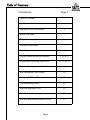
Table of Contents
Table of Contents 2
Specification Sheet 3
Important Safety Information 4
Before You Start 5
Warm Up Exercises 6
Assembly Instructions 7
Power Requirements 8
Console Functions and Descriptions 9, 10, & 11
Program and Operating Instructions 12, 13, & 14
Program Descriptions and Profiles 15
Belt Adjustments and Tension 16
Change to MPH or KM 17
Troubleshooting Guide 18
Parts and Exploded View 19
Parts List 20
Warranty Registration (Mail In Form) 21
Information Page #
Page 2

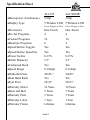
ALL855
ALL888HR
♦
Horsepower (Continuous) 2.0hp 3.0hp
♦
Display Type 5 Window LED 5 Window LED
Green Display w/Pace Green Display w/Pace
♦
Electronics One-Touch One-Touch
♦
Pre-Set Programs 4 4
♦
Custom Programs 10 10
♦
Heartrate Programs 0 2
♦
Speed/Incline Toggles Yes Yes
♦
Speed/Incline Speed bar Yes Yes
♦
Power Incline 0-15% 0-15%
♦
Roller Diameter 2.5” 2.5”
♦
Cushioned Deck Yes Yes
♦
Speed Range 0-10mph 0-12mph
♦Ortho-Belt Size 20x56 ” 20x56”
♦
Side Hand Rails Yes Yes
♦
Foot Print 29x71” 29x71”
♦
Warranty Motor 10 Years 10 Years
♦
Deck and Belt 5 Years 5 Years
♦
Warranty Parts 3 Years 3 Years
♦
Warranty Labor 1 Year 1 Year
♦
Warranty Frame Lifetime Lifetime
Specification Sheet
PAGE 3

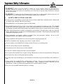
Important Safety Information
♦
WARNING!
Before using this treadmill or starting any exercise program, consult your physician.This is
especially important for persons over the age of 35 and/or persons with pre-existing health problems.The
manufacturer or distributor assumes no responsibility for personal injury or property damage sustained by or through
the use of this product.
♦
WARNING!
To reduce the risk of electrical shock, burns, fire, or other possible injuries to the user, it is
important to review this manual and the following precautions
before
operation.
♦
SAFETY PRECAUTIONS AND TIPS
♦
It is the owner’s responsibility to ensure that all users of this treadmill have read the Owner’s Manual and
are familiar with warnings and safety precautions.
♦
This treadmill has a user maximum capacity of 400 pounds.
♦
The treadmill should only be used on a level surface and is intended for indoor use only. The treadmill
should not be placed in a garage, patio, or near water and should never be used while you are wet. KEYS
recommends a treadmill mat be placed under the treadmill to protect floor or carpet and for easier cleaning.
♦
Follow safety information in regards to plugging in your treadmill. Keep the power cord away from the
incline wheels and do not run the power cord underneath your treadmill. Do not operate the treadmill with
a damaged or frayed power cord.
♦
Wear comfortable, good-quality walking or running shoes and appropriate clothing. Do not use the
treadmill with bare feet, sandals, socks or stockings.
♦
Always straddle the belt and allow it to start moving before stepping onto the belt.
♦
Hold on to handrails when adjusting speed, incline, or other controls.
♦
Always examine your treadmill before using to ensure all parts are in working order.
♦
Allow the belt to fully stop before dismounting.
♦
Pets should never be allowed near or on the treadmill.
♦
Do not leave children unsupervised near or on the treadmill.
♦
Never operate the treadmill where oxygen is being administered, or where aerosol products are being used.
♦
Never insert any object or body parts into any opening.
♦
For safety and to prevent damage to your treadmill, no more than one person should use the treadmill at a
time.
♦
Always unplug the treadmill before cleaning and/or servicing. Service to your treadmill should only be
performed by an authorized service representative, unless authorized and/or instructed by the
manufacturer. Failure to follow these instructions will void the treadmill warranty.
♦
Never leave the treadmill unattended while it is running.
PAGE 4

Thank you for purchasing a KEYS treadmill! The ALLIANCE 855 and 888 treadmill was designed to meet
your needs for cardiovascular exercise.
Before you start, please read the Owner’s Manual and become familiar with the operation of your new
treadmill.
♦
Remember to take the time to perform the stretching exercises provided on Page 6 to avoid injury.
♦
Do not stand on the walking belt while pressing the Power button or Start/Stop button.
♦
Always adjust the speed of the treadmill in small increments as this treadmill is capable of high speeds.
♦
If you are taking medication, consult your physician to see if the medication will affect your exercise
heart rate.
♦
If you have heart problems, you are not active, and/or are over the age of 35 years, do not use the pre-set
treadmill programs or start an exercise program without first contacting and receiving approval from your
physician.
♦
To avoid the risk of electrical shock, always keep the console dry. Do not spill liquids on the console.
KEYS recommends a sealed water bottle for beverages consumed while using the treadmill.
♦
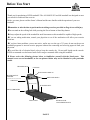
Please review the following picture below to familiarize yourself with the listed parts. This
manual covers several treadmills, so the one pictured below may not be identical to your particular
model.
Before You Start
PAGE 5
ELECTRONIC DISPLAY
CONSOLE
WATER BOTTLE
HOLDER
(WATER BOTTLE NOT INCLUDED)
SIDE HAND RAILS
CIRCUIT BREAKER
UPRIGHTS
MOTOR COVER
REAR ROLLER
ADJUSTMENT BOLTS
FOOT RAILS
WALKING BELT
READING RACK

Warm Up Exercises
EXERCISE GUIDELINES
WARNING
!
Before beginning this or any exercise program, you should consult your physician. This is espe-
cially important for individuals over the age of 35 or individuals with pre-existing health problems.
Warming up prepares the body for the exercise by increasing circulation, supplying more oxygen to the mus-
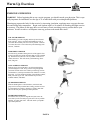
cles and raising body temperature. Begin each workout with 5 to 10 minutes of stretching and light exercise
to warm up. The photos on this page show several forms of basic stretching you may perform before your
workouts. In order to achieve an adequate warm-up, perform each stretch three times.
TOE TOUCH STRETCH
Stand bending your knees slightly and slowly bend forward
from your hips. Allow your back and shoulders to relax as
you reach down toward your toes as far as possible. Hold for
15 counts, then relax. This will stretch your hamstrings, back
of knees , and back.
HAMSTRING STRETCH
Sit with one leg extended. Bring the sole of the opposite foot
toward you and rest it against the inner thigh of your extended
leg. Reach toward your toes as far as possible. Hold for 15
counts, then relax. This will stretch your hamstrings, lower
back, and groin.
CALF/ACHILLES STRETCH
With one leg in front of the other, reach forward and place
your hands against a wall. Keep your back leg straight and
your back foot flat on the floor. Bend your front leg, lean for-
ward and move your hips toward the wall. Hold for 15 counts,
then relax. To cause further stretching of the Achilles tendons,
bend your back leg as well. This will stretch your calves,
Achilles tendons, and ankles.
QUADRICEPS STRETCH
With one hand against a wall for balance, reach back and
grasp one foot with your other hand. Bring your heel as close
to your buttocks as possible. Hold for 15 counts, then relax.
This will stretch your quadriceps and hip muscles.
INNER THIGH STRETCH
Sit with the soles of your feet together and your knees out-
ward. Pull your feet toward your groin area as far as possible.
Hold for 15 counts, then relax. This will stretch your quadri-
ceps and hip muscles.
PAGE 6

PAGE 7
Minor Assembly Required!
ALLIANCE 855/888HR
treadmill is shipped in two pieces: the console upright assembly, and the base
assembly. After opening the box, remove any packing materials from the treadmill. Do not throw away any
packing materials until the unit is working properly. The treadmill box contains a package that includes the
Owners Manual, a RED SAFETY KEY, and a belt adjustment tool. The 888HR will also contain the heart
rate chest strap.
The treadmill will not operate without the Red Safety Key.
The console upright assembly is attached to the base assembly. Place the unit on a clean, level surface near
an electrical outlet (extension cords are not recommended).
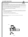
See Figure 1
1. Raise the console into an upright position. Loosely install both 3/4” buttonhead screws on each side of
the upright. Install and tighten each 3 1/2” x 5/16” bolt (2) with washers from the bottom of the base
frame through the upright lock (diag. 1).
2. Now tighten the buttonhead screws securely from step 1.
3. Install motor hood cover using 5/8” phillips head screws (8 screws).
Be sure the treadmill is level to the floor. The rear feet can be adjusted to level the treadmill.
Assembly is now complete!
Assembly Instructions
Figure 1

ARNG!
IMPROPER CONNECTION OF THE EQUIPMENT GROUNDING CONNECTOR CAN RESULT IN A
RISK OF AN ELECTRIC SHOCK. CHECK WITH A QUALIFIED ELECTRICIAN OR SERVICE MAN
IF YOU ARE IN DOUBT AS TO WHETHER THE PRODUCT IS PROPERLY GROUNDED. DO NOT
MODIFY THE PLUG PROVIDED WITH THE PRODUCT, IF IT WILL NOT FIT THE OUTLET, HAVE
A PROPER OUTLET INSTALLED BY A QUALIFIED ELECTRICIAN.
This treadmill can be seriously damaged by sudden voltage changes in your home’s electrical power.
Voltage spikes, surges, and noise interference can result from weather conditions or from other appliances
being turned on or off. To reduce the possibility of treadmill damage, always use a surge protector (not
included) with your treadmill.
Surge protectors can be purchased at most hardware stores. The manufacturer recommends a single outlet
surge protector with a UL 1449 rating as a Transient Voltage Surge Suppressor (TVSS) with a UL
suppressed voltage rating of 400V or less and an electrical rating of 120VAC, 15 amps.
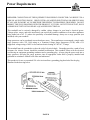
This treadmill must be grounded to reduce the risk of electrical shock. Grounding provides a path of least
resistance for electric current, should the treadmill malfunction. This treadmill comes with an electrical
cord having an equipment-grounding conductor and a grounding plug. Always plug the power cord into a
surge protector, and plug the surge protector into an appropriate outlet that is properly installed and
grounded in accordance with all local codes and ordinances.
This product is for use on a nominal 120-volt circuit and has a grounding plug that looks like the plug
illustrated in the drawing below.
Power Requirements
PAGE 8

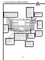
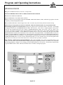
Console Functions and Descriptions
POWER
- Press to on. Allow
6-8 seconds while the
electronics perform a self
check prior to pressing other
buttons.
START/STOP
- This button
starts the treadmill belt
moving. There is a 4 second
countdown built in as a safety
feature to let you know the
treadmill belt is about to start
moving.
Use the START/STOP button
also to stop your treadmill
after your workout. The belt
will gradually come to a stop
after pressing the button.
PAUSE
- Press to
temporarily pause
your workout
while in use. The
treadmill is
designed with an
automatic power
off feature after 5
minutes in the
pause mode.
SPEED
- Use to either
increase (UP arrow) or
decrease (DOWN arrow)
the speed. These buttons
are also used while
programming SPEED and
TIME.
INCLINE - Use to either
increase (UP arrow) or
decrease (DOWN arrow)
the incline. These buttons
are also used while
programming INCLINE.
ONE TOUCH SPEED BAR -
Use to either increase or
decrease the speed. Each
number indicates MPH.
Pressing one of the buttons will
gradually increase or decrease
the speed to the new setting.
ONE TOUCH INCLINE
BAR
- Use to either increase or
decrease the incline. Each
number indicates percent of
grade. Pressing one of the
buttons will gradually increase
or decrease the incline to the
new setting.
CONSOLE SAFETY KEY
- Place the RED
Safety Key here prior to turning power on.
THE TREADMILL WILL NOT OPERATE
WITHOUT THE SAFETY KEY ATTACHED.
The safety key is equipped with a string and
clip that will clip to your clothing. This is an
important safety feature that will automatically
turn the power off if you should trip or fall
while using the treadmill.
PROGRAM BUTTONS - These buttons are used to
access each of the four programs: Fat Burn, Cardio,
Warm Up, and Cross Training. Each program has one
preset program, and two additional custom programs in
the P1 and P2 mode. See the “Program and Operating
Instructions” on page 12.
ENTER
- Use
the Enter button
while setting
program time,
speed, and
incline options.
See page 12 for
complete
instructions.
PAGE 9

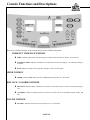
Console Functions and Descriptions
There are five display windows on the control panel to provide feedback information.
WORKOUT TIME/PACE WINDOW
♦
TIME:
Indicates elapsed time after pressing start in minutes and seconds (0-99 minutes, 0-59 seconds)
♦
INTERVAL TIME:
Indicates countdown in seconds to the next interval starting at 5 seconds and counting to
0 seconds
♦
PACE:
Indicates amount of time required to complete 1 mile at current speed.
SPEED WINDOW
♦
SPEED:
Indicates MPH (miles per hour) or KMH (kilometer per hour) in .1 increments
DISTANCE / CALORIES WINDOW
♦
DISTANCE:
Indicates Miles or Kilometers traveled in .01 increments up to 9.99 and .1 increments starting at
10.0
♦ CALORIES:
Indicates estimated calories used based on 150 lb. person at the indicated speed, incline, and
time
INCLINE WINDOW
♦
INCLINE: Indicates incline in percent of grade 0-12% in .5 increments
PAGE 10

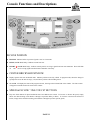
INCLINE WINDOW
♦
INCLINE:
Indicates incline in percent of grade 0-12% in 1 increments
♦
PULSE (888HR Model Only): Indicates current heart rate
♦
HEART
(888HR Model only): Indicates control panel is receiving a signal from heart rate transmitter. Heart will blink
on and off if receiving signal from Heart Rate Transmitter chest strap.
♦
CENTER BRICKYARD WINDOW
♦ Displays quarter mile track in Manual mode. Indicates position on track by a blink. In program mode, shows the change in
speed profile across the interval range (1-10) and shows position with a blinking action.
♦
The 880HR will display the name of the program selected, showing on the left hand side of the window. The LAP counter
will appear in manual mode in the center of the window.
♦
SPEED & INCLINE “ONE-TOUCH” BUTTONS
♦
Easy One-Touch buttons for Speed and Incline have been added to the console. To increase or decrease the speed, simply
choose the desired setting (each number 2 through 8 represents Miles per Hour). To increase or decrease the amount of
incline, simply choose the desired setting (each number 2 through 8 represents percent grade).
Console Functions and Descriptions
PAGE 11

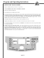
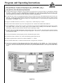
♦
QUICK START / MANUAL MODE
♦
Plug into a standard wall outlet (110-Volt AC, 15-amp circuit).
♦
ATTACH THE RED SAFETY KEY TO CENTER OF CONSOLE
.
♦ Stand on the treadmill and straddle belt.
♦
Press POWER button. The TIME window will flash.
♦
Press START/STOP button. Belt will begin to move after 4 seconds. Step on belt slowly after the belt starts moving. Speed
or incline may be adjusted by using the appropriate UP (increase) or DOWN (decrease) buttons. Speed and Incline can also
be adjusted using the “One Touch” buttons labeled 2 through 8, or by using the toggle switches located on the handlebars.
For speed and incline adjustments while using the treadmill, try the convenient handlebar toggles switches. The left
handlebar switch is for incline, while the right handlebar switch adjusts the speed.
♦
To end your workout
, press START/STOP button. Belt will gradually slow to zero.
♦
To pause your workout
, press PAUSE. The treadmill will automatically shut off after five (5) minutes.
♦
To re-start after pausing: Press the PAUSE button. WARNING: The treadmill belt will resume at the speed the treadmill
was moving before pausing.
♦
Countdown Time, Preset Speed and/or Incline
: Time, Speed, and Incline may be preset prior to getting started. After
pressing the POWER button, the time window will blink. Use the SPEED UP or DOWN arrows to select your workout time,
then press the ENTER PROGRAM button located on the left hand side of the console below the program buttons. The
SPEED window will now be flashing. Using the same + or – arrows, select the speed for your workout, then press ENTER
PROGRAM. Now the INCLINE window will be flashing. Use the INCLINE + or – arrows to set your workout incline, then
press ENTER PROGRAM. To start, press the START/STOP button.
Program and Operating Instructions
PAGE 12

♦
PROGRAM MODE
♦Plug into a standard wall outlet (110-Volt AC, 15-amp circuit).
♦
ATTACH THE
RED SAFETY KEY TO THE CENTER OF THE CONSOLE
.
♦
Stand on the treadmill and straddle belt.
♦Press POWER button. The TIME window will flash.
♦There are three (4) pre-set programs on the 855 and 888HR. Both include Fat Burn, Cardio, and Warm Up programs. Select the
program by pressing the appropriate button.
♦
Press START/STOP button. Belt will begin to move after 4 seconds. Step on belt slowly after the belt starts moving.
♦
Each of the pre-set programs (4) can also be customized. Follow the instructions below for your particular model.
♦
Customizing programs in P1 and P2 Mode:
Each pre-set program can be customized in the P1 or P2 mode. After making
the program selection, the CALORIE/DISTANCE window will read “OP.” ”OP” refers to “original program” and is preset.
Press the same program button once more, and the CALORIE/DISTANCE window will read P1. The “P1” mode is now
accessed. You can now program the Time, Speed, and Incline in P1 mode, which will save your entered information for future
use. The time window will blink. Use the SPEED UP or DOWN arrows to select your workout time, then press the ENTER
PROGRAM button located on the left hand side of the console below the program buttons. The SPEED window will now be
flashing. Using the SPEED UP or DOWN arrows, select the speed for your workout, then press the ENTER PROGRAM button.
Now the INCLINE window will be flashing. Use the INCLINE UP or DOWN arrows to set your workout incline, then press the
ENTER PROGRAM button. To start, press the START/STOP button. To access P2 mode, press the selected program button
three times (once for OP, twice for P1, three times for P2). Follow the above procedure to customize.
♦
TO CHANGE A PREVIOUSLY PROGRAMMED P1, P2, or user program:
Once you have programmed the P1 or P2
modes, you will need to use the PAUSE button to change the program you previously entered. For instance, if P1 in Fat Burn
has been programmed, to change to a new setting, press the Fat Burn button twice to access P1. Then press the PAUSE button
to get the TIME window to flash. Follow the directions above to continue to change the program.
Program and Operating Instructions
PAGE 13

Program and Operating Instructions
♦
Heart Rate Control Instructions (888HR only)
♦
HEART RATE PROGRAM MODE
♦
The Heart Rate program is designed to keep your heart rate a desired level of “beats per minute” by automatically adjusting
the incline. For example, if you have programmed in a desired heart rate of 105 beats per minute and your heart rate is only
95 beats per minute (you must be wearing Heart Rate Transmitter), the incline will automatically increase to intensify the
work load, and increase you heart rate to the 105 beats per minute you programmed.
♦
If your heart rate is above your programmed amount of beats per minute the incline will automatically decrease to lower your
heart rate. You may at any time during the Heart Rate Program adjust/override the speed and or incline by simply pressing
the correct corresponding buttons. You may change your “Target Heart Rate” at any time during the program by pressing
the TARGET + or TARGET – buttons.
♦
Plug into a standard wall outlet (110-Volt AC, 15-amp circuit). Attach Safety Key to console
♦ Place the Heart Rate transmitter strap across chest against the skin. Stand on the treadmill and straddle belt.
♦ Press POWER button. There will be an eight (8) second delay after pressing the POWER button before data can be entered.
The TIME window will flash. The “Heart” shape on the treadmill will be flashing if the Heart Rate Transmitter is
transmitting. Adjust the strap on the chest until the console is picking up a signal.
♦
For Quick Start, press START/STOP button. Belt will begin to move after 4 seconds. Step on belt slowly after the belt starts
moving. Speed or incline may be adjusted by using the appropriate + (increase) or – (decrease) buttons. Heart rate will read
out in the Incline window.
♦ To select the Heart Rate Control program, press the “Heart Rate Program” button.
♦ The incline window will flash “125”, which is the default program target heart rate.
♦
Adjust Target Heart Rate to desired level with the TARGET + or – buttons.
♦ Press START/STOP button, or continue instructions below to program Time, and Speed.
♦ You can now program the Time and Speed. The time window will blink. Use the SPEED + or – arrows to select your
workout time, then press the ENTER PROGRAM button. The SPEED window will now be flashing. Using the SPEED +
or – arrows, select the maximum speed for your workout, then press ENTER PROGRAM. To start, press the START/STOP
button.
PAGE 14

12
11
10
9
8
7
6
5
4
3
2
1
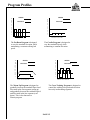
Program Profiles
1 2 3 4 5 6 7 8 9 10
SPEED
INCLINE
The
Fat Burn Program
is designed
to vary the treadmill elevation, while
maintaining a constant walking belt
speed.
12
11
10
9
8
7
6
5
4
3
2
1
1 2 3 4 5 6 7 8 9 10
SPEED
INCLINE
The Cardio Program is designed to
vary the treadmill Speed, while
maintaining a constant Elevation.
12
11
10
9
8
7
6
5
4
3
2
1
1 2 3 4 5 6 7 8 9 10
SPEED
INCLINE
The Warm Up Program is designed to
gradually increase the treadmill Speed and
Elevation in the first segment (warm up)
and gradually decrease the treadmill Speed
and Elevation in the last segment (cool
down). This is also known as a
Plateau program.
PAGE 15
The Cross Training Program is designed to
control the walking belt speed and elevation
inversely in alternating segments.
1 2 3 4 5 6 7 8 9 10
12
11
10
9
8
7
6
5
4
3
2
1
SPEED
INCLINE

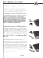
WARNING! Do not overtighten rollers! This will cause
premature roller bearing failure!
Belt adjustment and tension performs two functions: adjustment for
tension and centering. Your new treadmill comes pre-adjusted from
the factory for tension and centering. Please follow the procedures
below if the belt shifts to the left or right or while walking:
WALKING BELT IS SHIFTING TO THE LEFT (Diagram 1)
First, turn treadmill on to run at 1 mph. Using the hex key provided,
turn the left rear roller adjustment bolt ¼ turn in the clockwise
direction. Next, run the treadmill at 2.5 mph. You should see the
belt start to correct itself, moving back towards the center. Repeat
the above procedure until the walking belt is centered. It may be
necessary to set walking belt tension once you have completed this
procedure if the belt feels like it is slipping while walking. Refer
below to the “Walking Belt Slipping” instructions.
WALKING BELT IS SHIFTING TO THE RIGHT (Diagram 2)
First, turn the treadmill on to run at 1 mph. Using the hex key
provided, turn the right rear roller adjustment bolt ¼ turn in the
clockwise direction. Next, run the treadmill at 2.5 mph. You
should see the belt start to correct itself, moving back towards the
center. Repeat the above procedure until the walking belt is
centered. It may be necessary to set walking belt tension once you
have completed this procedure if the belt feels like it is slipping
while walking. Refer below to the “Walking Belt Slipping”
instructions.
WALKING BELT IS SLIPPING DURING USE (Diagram 3)
First, unplug the power cord from the surge protector. Using the
hex key provided, turn both left and right rear roller adjustment bolts
the same distance, usually a ¼ turn in the clockwise direction. Plug
the power cord back into the surge protector and run the treadmill at
2.5 mph. You should now walk on the belt to determine if the belt
is still slipping. Repeat the above procedure until the walking belt is
not slipping. The tension should be just tight enough not to slip.
Turning the hex key counter clockwise brings the rear rollers and
belt towards you. Turning the hex key clockwise pushes the rear
roller and belt away form you.
PAGE 16
Belt Adjustment and Tension

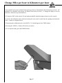
Your treadmill will operate in British Units (miles per hour) or International Units (kilometers per hour). All
treadmills are calibrated at the factory for British Units (miles per hour). To change the display to read in
kilometers, follow the steps described here:
1) Turn power OFF on the console. (Do not unplug treadmill) Attach the magnet safety key to the console.
2) Activate the calibration mode switch by inserting the eraser end of a pencil into the opening in the backside
of the console (see diagram below).
3) Depressing the calibration mode switch ONCE; CL11 should appear in the TIME window.
4) Pressing the SPEED +/- button will activate your choice.
5) To accept the setting, press the POWER button.
Change Miles per hour to Kilometers per hour
Page 17

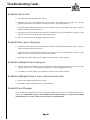
Troubleshooting Guide
Treadmill will not start.
1) Is the RED Safety Key Attached to the Console?
2) Make sure the power cord is plugged into a surge protector, the surge protector is plugged into a properly
grounded outlet, and the surge protector is turned on. (Refer to “Power Requirements”)
3) Check the circuit breaker located on the front of the treadmill. If the switch protrudes, it has tripped. Wait five
minutes and then press the switch back in.
4) Check the house electrical breaker box and the circuit breaker for the room the treadmill is located in. If it has
tripped, reset or have an electrician replace the breaker in home.
5) Have an electrician check for inadequate voltage at the outlet.
Treadmill looses power during use.
1) Check the circuit breaker located on the front of the treadmill. If the switch protrudes, it has tripped. Wait five
minutes and then press the switch back in.
2) Check the house electrical breaker box and the circuit breaker for the room the treadmill is located in. If it has
tripped, reset or have an electrician replace the breaker in home.
3) If treadmill still will not operate, please call Keys Technical Service at (888) 340-0482.
Treadmill walking belt slows during use.
1) Check to make sure the treadmill is securely plugged into an UL-listed surge protector, rated at 15 amps, with a
14-guage cord of five feet or less and the surge protector is securely plugged into the outlet.
2) If treadmill still will not operate, please call Keys Technical Service at (888) 340-0482.
Treadmill walking belt slips or is not centered on rear roller.
1) Refer to “Belt Adjustment and Tension” section.
2) Need help? Call Keys Technical Service at (888) 340-0482.
Treadmill Error Messages.
2)Your treadmill is equipped with a software package that enables error messages to be displayed when there is a
problem. To avoid possible damage to the treadmill and the possibility of injury, do not operate the treadmill
until the problem is corrected. Call Keys Technical Service at (888) 340-0482.
Page 18 Page 18

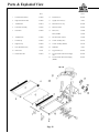
Parts & Exploded View
Part # Part #
1 Left Side Extrusion Rail 05-0028 12 Front Wheel (2) 06-0039
2 Right Side Extrusion Rail 05-0028 13 Uprights for Console (2) various
3 Treadmill Belt 04-0014 14 Motor Hood Cover Top 06-0040
4 Front Roller Assembly 24-0106 15 Motor Drive Belt 04-0007
5 Rear Roller 09-0009 16 Motor (855) 12-0004
Motor (888HR) 12-0026
6 Treadmill Deck 03-0008 17 Elevation Motor (acuator) 12-0026
7 Left End Cap 06-0043 18 Console Assembly (855) 24-0191
8 Right End Cap 06-0042 19 Console Assembly (888HR) 24-0192
9 Rear Adjustable Foot (2) 10-0008 20 Handlebars various
10 Main Frame various 21 Toggle switches (2) 08-0027
11 Bottom Motor Pan 06-0041 22 Lower Electronics M/Control P/Supply
(855)
08-0050
22 Lower Electronic M/Control P/Supply
(888HR)
08-0016
Page 19

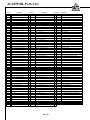
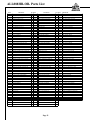
ALL855OB- Parts List
Page 20
PART # DESCRIPTION QTY PART # DESCRIPTION QTY PART # DESCRIPTION
02-0004 SCREW-8x5/8 PHIL PH AB BLACK 9 08-0004 BREAKER-CIRCIT-15AMP 1 19-0015 BRACKET-MOTOR COVER
02-0005 SCREW-8x5/8 PPH HILO BLACK TPB 11 08-0112 MEBRANE LED FOR WEDGE CONSOLE 1 19-0019 GUIDE BELT GLAVANIZED
02-0007 NUT 5/16-18 NYLOCKZP 2 08-0088 MEMBRANE-LED/LCD OWER 1 19-0030 SPACER-ENCODER
02-0009 NUT-HEX 5/16 WIZ-FL-LK-ZP 4 08-0027 SWITCH-REMOTE-W/HARNESS 2 19-0042 BRKT-SIDE FRAME ACTUATOR
02-0013 WASHER LOCK 1/4" 16 08-0047 ENCODER-OPTICAL-ALEPH 1 19-0043 BRKT-MOTOR MOUNT
02-0014 BOLT-HEX 1/4-20x2 1/2" GRADE 5 ZP 2 08-0077 CORE-ERRITE 1 19-0044 BRKT-ACTUATOR SUPPORT
02-0016 BOLT-HEX 3/8-16x2 1/2" GRADE 5 1 08-0050 CONTROLLER-REPLACES 08-0013 1 19-0047 BRKT-ELEVATION ACTURATOR
02-0017 NUT-NYLOCK HEX 3/8-16 2 09-0008 ROLLER-DRIVE .5:-8800/8500 1 19-0048 BRKT-REAR ROLLER
02-0019 BOLT-CARRIAGE 10-24x1 1/2 4 09-0009 ROLLER-IDLER 2.5"-8800/8500 1 19-0050 BRKT-ACTUATOR BRACE
02-0021 WASHER 9/32 5/8 1/8THICK ZP 2 10-0002 ISOLATOR-BOARD 3/4" 8 19-0052 BRKT-ELEVATION ACTURATOR
02-0022 NUT-NYLOCK HEX 10-24 4 10-0008 FOOT-REAR-KEYS SERIES 2 19-0057 BRKT-CHANNEL SUPPORT BOSS
02-0023 CLIP-ROTO HW12 2 10-0017 TAPE-FOAM-1"X75ft 1 19-0062 BRKT-ACTUATOR
02-0024 CARRIAGE BOLT 5/16x1 GRADE 5 ZP 4 10-0021 MOLDED GRIP OVAL NEW 2 19-0064 BRKT-STRAIN RELIER/BREAKER
02-0027 NUT-T HF 14209H-DB 16 11-0002 BUSHING-REAR ELEVAION 4 19-0065 BRKT-UPRIGHT BRACE
02-0028 SWITCH-MAGETIC KILL-YIHAN 1 11-0012 FLYWHEEL 5.88 10J-1.250 REPLACES 11- 1 19-0079 BRKT-BELT GUIDE
02-0030 SCREW-HEX TRILOBE 8-32x1/2" 1 12-0004 MOTOR-MAGNETEK 2.0HP-223526 1 19-0089 PLATE CONTROLLER KEYS8500
02-0031 BOLT-HEX 3/8-16x1 3/4" GRADE 5ZP 1 12-0026 ACTUATOR-600# BOSS 1 19-0101 BRKT-CONSOLE BRACE
02-0036 SCREW-PPH 8x5/8 GREEN HEAD 3 13-0011 CORD-POWER-90" 1 19-0107 SLUG-EMERGENCY STOP RED
02-0038 WRENCH-ALLEN 3/16 SHAFT ARM 1 13-0014 WIRE-JUMPER 12"-220V-KEYS SERIES 1 19-0128 BRKT-RIGHT STABILIZER
02-0042 SCREW#8x5/8' SD BLACK 2 13-0020 HARNESS CONTROLLER 80" 1 19-0129 BRKT-LEFT STABILIZER
02-0050 NUT-NYLOCK HEX 1/4-20 4 13-0034 WIRE-MOTOR LEAD EXTENSION 8" 1 19-0130 PLATE-CONSOLE ALLI-14GA-EC850/880
02-0082 SCREW-BUTTON HEAD 5/16-18x2 1/2' 2 13-0040 HARNESS CONTROL PANEL +6" 1 19-0131 BRKT-RIGHT FILLER
02-0084 BOLT-CARRIAGE 5/16x:RADE 5 2 14-0026 DECAL-WARNING CONSOLE-ALL GRAY 1 19-0132 BRKT-LEFT FILLER
02-0085 HEX NUT 1/2-13 4 14-0027 DECAL-EMERGENCY STOP-RED 1 19-0151 BRKT-RT U/R STIFFENER
02-0090 HEX BOLT 1/4-20x1 3/4 HC 2 14-0354 OVERLAY CONSOLE ALL855-OB 1 19-0152 BRKT RT U/R & FRT ROLLER
02-0095 SCREW-BUTTON HD 5/16-18x1" HSC BLK 2 14-0205 DECAL DISCONNECT-MOTOR COVER 1 19-0153 BRKT LT U/R & FRT ROLLER
02-0099 WASHER -SFW 3/8X7/8X1/8" THICK 1 14-0226 DECAL-SIDE FRAME-EC850 2 19-0154 BRKT MOTOR SHELF REVISED 19-0088
02-0100 BOLT HEX 5/16-18x3 1/2"GRADE 8 2 14-0321 DECAL-10YR MOTOR WARRANTY 1 19-0160 BRKT MOTOR COVER SUPPORT
02-0105 INDRTY-5/16-18 HEAVY WAL AVK 2 14-0336 DECAL MTR COVER ALL ALLIANCE 3 20-0019 PROC-BELT GUIDE TB 17-0017
02-0119 HEX SCREW HD 1/4-20x3 1/4" 8 14-0351 DECAL SPEED SERIGRAPH 1 20-0020 PROC-FRAME TUBE 17-0018
02-0125 SCREW-5/16-18x3/4"BUTTON HD BLACK 2 14-0352 DECAL INCLINE SERIGRAPH 1 20-0023 PROC-LOWER ELEVATION END TB 17-0021-OBS
02-0131 HEX NUT 5/16-18 3 15-0029 DIAGRAM-WIRING-MAGNETEK 1 20-0027 PROC-FRAME BRACE 17-0016
02-0137 PLUG PUSH-IN 2 15-0080 MANUAL-EC880HR-EC850 1 20-0060 PROC-RT CURVED U/R 17-0052
02-0141 PUSH NUT BLACK.112 SHAFT 6 16-0018 BOX-BOTTOM-KEYS SERIES 1 20-0061 PROC-LT CURVED U/R 17-0052
02-0143 HEX BOLT 1/4-20x1" 8 16-0017 BOX-TOP KEYS/SCIFIT 1 20-0066 PJROC OVAL HBAR NEW 17-0040
03-0008 WALKBOARD KEYS SERIES NOTCHED 1 16-0020 PAD-TOP TRAY-KEYS SERIES 1 20-0102 PROC LOWER ELEV END TB REVISED
04-0007 BELT-POLY V-260J10-KEYS SERIES 1 16-0033 ANGLE FOAM-6FT PIECES-CUT INTO 9PCS 1 21-0012 ELEVATION X-TB-NOTCHED BOTH ENDS
04-0014 WALKBELT ORTHO 19.75x116.5-P7 2 PLY 1 16-0039 PAD END EC850/880 2 21-0028 RT CURVED UPRIGHT-WELD TAB
05-0028 EXTRUSION SIDE BOARD LT&RT 2 16-0040 PAD SIDES EC850/880 2 21-0029 LT CURVED UPRIGHT-WELD TAB
06-0014 BUSHING-STRAIN RELIEF #1237 1 16-0041 PAD HANDRAILS EC850/880 1 21-0030 UPRIGHT STIFFENER
06-0016 TIES-WIRE 7 16-0043 BOX-TOP INVERTED 16-0017 1 21-0031 STRAIGHT U/R SAW CUT TO 2 PIECES
06-0021 CLAMP WIRE 3367 7/16 1 16-0061 ANGLE BOARD 6" 4 21-0031 STRAIGHTENED U/R SAW CUT TO 2 PIECES
06-0024 CLIP-ALLEN WRENCH 1 16-0062 ANGLE BOARD 33 3/4" 4 22-0013 LOWER ACTUATOR SUB-ASSEMBLY
06-0038 PULLEY-KEY SERIES-4.5" 1 17-0015 RECT 1x1 1/2x11GAx25 15/16 1 22-0026 UPPER ACTUATOR ASSEMBLY
06-0039 WHEEL-KEYS SERIES-2.5" 2 17-0016 RECT 1x1 1/2x12GAx26 7/16 1 22-0051 99"CONSOLE ASSEMBLY
06-0040 MOTOR COVER 1 17-0017 RECT 1x3x12GAx26 7/16 1 22-0059 RT U.R BRKT SUB-ASSEMBLY
06-0041 PAN-BOTTOM 1 17-0018 RECT 1x3x12GAx166 1 22-0060 LT U/R BRKT SUB-ASSEMBLY
06-0042 ENDCAP-RIGHT 1 17-0020 RECT 1x2x12GAx4 7/16-PUNCHED 2 23-0038 DECK FRAME ASSEMBLY
06-0043 ENCAP-LEFT 1 17-0021 RECT 1x2x12GAx3 9/16 2 23-0066 UPRIGHT ASSEMBLY-ALLIANCE/BOSS
06-0071 FAN 5"-5/8" ID 2 17-0022 RECT 1x2x12GAx23 7/8 1 24-0106 FRONT ROLLER ASSEMBLY-LEYS8800/8500
06-0084 BAG-PLASTIC 12x12 3MIL-INST PACKET 1 17-0040 OVAL 1.094x2x16GAx17.25 2 24-0191 CONSOLE ASSEMBLY ALL855-OB
06-0118 PLASTIC SWITCH HOUSING BLK FOR OVA
L
2 17-0046 TUBE-RESET GUIDE 1 26-0059 INST PACKET-EC850
06-0140 INSERT LED FOR CONSOLE 1 17-0052 RECT-2x4x14GAx100" 1
06-0160 CONSOLE ALLIANCE SHELL LED/LCD 1 17-0053 RECT-1x3x16GAx24 7/16" 1
07-0050 ELECTRONICS 5 WIN LED GREEN 1
Page is loading ...
Page is loading ...
-
 1
1
-
 2
2
-
 3
3
-
 4
4
-
 5
5
-
 6
6
-
 7
7
-
 8
8
-
 9
9
-
 10
10
-
 11
11
-
 12
12
-
 13
13
-
 14
14
-
 15
15
-
 16
16
-
 17
17
-
 18
18
-
 19
19
-
 20
20
-
 21
21
-
 22
22


Trulife Alliance Fitness Treadmills Alliance 855 Owner's manual
- Type
- Owner's manual
- This manual is also suitable for
Ask a question and I''ll find the answer in the document
Finding information in a document is now easier with AI
Other documents
-
Alliance Laundry Systems 815 User manual
-
Keys Fitness 6600t User manual
-
-
-
-
-
 Image 4600T User manual
-
-
-
 Smooth Fitness SMT9.2HRAB User manual

