Page is loading ...

Where Do I Find Everything I Need for
Process Measurement and Control?
OMEGA…Of Course!
TEMPERATURE
Thermocouple, RTD & Thermistor Probes,
Connectors, Panels & Assemblies
Wire: Thermocouple, RTD & Thermistor
Calibrators & Ice Point References
Recorders, Controllers & Process Monitors
Infrared Pyrometers
PRESSURE, STRAIN AND FORCE
Transducers & Strain Gages
Load Cells & Pressure Gages
Displacement Transducers
Instrumentation & Accessories
FLOW/LEVEL
Rotameters, Gas Mass Flowmeters & Flow
Computers
Air Velocity Indicators
Turbine/Paddlewheel Systems
Totalizers & Batch Controllers
pH/CONDUCTIVITY
pH Electrodes, Testers & Accessories
Benchtop/Laboratory Meters
Controllers, Calibrators, Simulators & Pumps
Industrial pH & Conductivity Equipment
DATA ACQUISITION
Data Acquisition & Engineering Software
Communications-Based Acquisition Systems
Plug-in Cards for Apple, IBM & Compatibles
Datalogging Systems
Recorders, Printers & Plotters
HEATERS
Heating Cable
Cartridge & Strip Heaters
Immersion & Band Heaters
Flexible Heaters
Laboratory Heaters
ENVIRONMENTAL
MONITORING AND CONTROL
Metering & Control Instrumentation
Refractometers
Pumps & Tubing
Air, Soil & Water Monitors
Industrial Water & Wastewater Treatment
pH, Conductivity & Dissolved Oxygen Instruments
M3549/1299
www.omega.com
e-mail: [email protected]
omega.com
TM
®
User’s Guide
M-3549/1299(HH303) 1/23/00 7:55 PM Page 2
OMEGANETTE
®
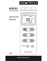
HH303
Type K J Thermometer

WARRANTY/DISCLAIMER
OMEGA ENGINEERING, INC. warrants this unit to be free of defects in materials and
workmanship for a period of 13 months from date of purchase. OMEGA’s WARRANTY
adds an additional one (1) month grace period to the normal one (1) year product
warranty to cover handling and shipping time. This ensures that OMEGA’s customers
receive maximum coverage on each product.
If the unit malfunctions, it must be returned to the factory for evaluation. OMEGA’s
Customer Service Department will issue an Authorized Return (AR) number immediately
upon phone or written request. Upon examination by OMEGA, if the unit is found to be
defective, it will be repaired or replaced at no charge. OMEGA’s WARRANTY does not
apply to defects resulting from any action of the purchaser, including but not limited to
mishandling, improper interfacing, operation outside of design limits, improper repair, or
unauthorized modification. This WARRANTY is VOID if the unit shows evidence of having
been tampered with or shows evidence of having been damaged as a result of excessive
corrosion; or current, heat, moisture or vibration; improper specification; misapplication;
misuse or other operating conditions outside of OMEGA’s control. Components which
wear are not warranted, including but not limited to contact points, fuses, and triacs.
OMEGA is pleased to offer suggestions on the use of its various products. However,
OMEGA neither assumes responsibility for any omissions or errors nor assumes
liability for any damages that result from the use of its products in accordance with
information provided by OMEGA, either verbal or written. OMEGA warrants only that
the parts manufactured by it will be as specified and free of defects. OMEGA MAKES
NO OTHER WARRANTIES OR REPRESENTATIONS OF ANY KIND WHATSOEVER,
EXPRESS OR IMPLIED, EXCEPT THAT OF TITLE, AND ALL IMPLIED WARRANTIES
INCLUDING ANY WARRANTY OF MERCHANTABILITY AND FITNESS FOR A
PARTICULAR PURPOSE ARE HEREBY DISCLAIMED. LIMITATION OF LIABILITY: The
remedies of purchaser set forth herein are exclusive, and the total liability of OMEGA
with respect to this order, whether based on contract, warranty, negligence,
indemnification, strict liability or otherwise, shall not exceed the purchase price of the
component upon which liability is based. In no event shall OMEGA be liable for
consequential, incidental or special damages.
CONDITIONS: Equipment sold by OMEGA is not intended to be used, nor shall it be used: (1)
as a “Basic Component” under 10 CFR 21 (NRC), used in or with any nuclear installation or
activity; or (2) in medical applications or used on humans. Should any Product(s) be used in
or with any nuclear installation or activity, medical application, used on humans, or misused
in any way, OMEGA assumes no responsibility as set forth in our basic WARRANTY/
DISCLAIMER language, and, additionally, purchaser will indemnify OMEGA and hold
OMEGA harmless from any liability or damage whatsoever arising out of the use of the
Product(s) in such a manner.
RETURN REQUESTS / INQUIRIES
Direct all warranty and repair requests/inquiries to the OMEGA Customer Service
Department. BEFORE RETURNING ANY PRODUCT(S) TO OMEGA, PURCHASER MUST
OBTAIN AN AUTHORIZED RETURN (AR) NUMBER FROM OMEGA’S CUSTOMER SERVICE
DEPARTMENT (IN ORDER TO AVOID PROCESSING DELAYS). The assigned AR number
should then be marked on the outside of the return package and on any correspondence.
The purchaser is responsible for shipping charges, freight, insurance and proper packaging
to prevent breakage in transit.
FOR WARRANTY
RETURNS, please have
the following information available BEFORE
contacting OMEGA:
1. Purchase Order number under which the
product was PURCHASED,
2. Model and serial number of the product
under warranty, and
3. Repair instructions and/or specific
problems relative to the product.
FOR NON-WARRANTY REPAIRS,
consult
OMEGA for current repair charges. Have
the following information available
BEFORE contacting OMEGA:
1. Purchase Order number to cover the
COST of the repair,
2. Model and serial number of the
product, and
3. Repair instructions and/or specific
problems relative to the product.
OMEGA’s policy is to make running changes, not model changes, whenever an improvement is possible.
This affords our customers the latest in technology and engineering.
OMEGA is a registered trademark of OMEGA ENGINEERING, INC.
© Copyright 1999 OMEGA ENGINEERING, INC. All rights reserved. This document may not be copied,
photocopied, reproduced, translated, or reduced to any electronic medium or machine-readable form, in whole or
in part, without the prior written consent of OMEGA ENGINEERING, INC.
Servicing North America:
USA: One Omega Drive, Box 4047
ISO 9001 Certified Stamford CT 06907-0047
Tel: (203) 359-1660 FAX: (203) 359-7700
e-mail: [email protected]
Canada: 976 Bergar
Laval (Quebec) H7L 5A1
Tel: (514) 856-6928 FAX: (514) 856-6886
e-mail: [email protected]
For immediate technical or application assistance:
USA and Canada: Sales Service: 1-800-826-6342 / 1-800-TC-OMEGA
®
Customer Service: 1-800-622-2378 / 1-800-622-BEST
®
Engineering Service: 1-800-872-9436 / 1-800-USA-WHEN
®
TELEX: 996404 EASYLINK: 62968934 CABLE: OMEGA
Mexico: Tel: (001) 800-826-6342 FAX: (001) 203-359-7807
En Espan˜ol: (001) 203-359-7803 e-mail: [email protected]
Servicing Europe:
Benelux: Postbus 8034, 1180 LA Amstelveen, The Netherlands
Tel: +31 (0)20 6418405 FAX: +31 (0)20 6434643
Toll Free in Benelux: 0800 0993344
e-mail: [email protected]
Czech Republic: Rudé armády 1868, 733 01 Karviná 8
Tel: +420 (0)69 6311899 FAX: +420 (0)69 6311114
Toll Free: 0800-1-66342 e-mail: [email protected]
France: 9, rue Denis Papin, 78190 Trappes
Tel: +33 (0)130 621 400 FAX: +33 (0)130 699 120
Toll Free in France: 0800-4-06342
e-mail: [email protected]
Germany/Austria: Daimlerstrasse 26, D-75392 Deckenpfronn, Germany
Tel:+ 49 (0)7056 3017 FAX: +49 (0)7056 8540
Toll Free in Germany: 0800 TC-OMEGA
SM
e-mail: [email protected]
United Kingdom: One Omega Drive, River Bend Technology Centre
ISO 9002 Certified Northbank, Irlam, Manchester
M44 5EX United Kingdom
Tel: +44 (0)161 777 6611 FAX: +44 (0)161 777 6622
Toll Free in United Kingdom: 0800-488-488
e-mail: [email protected]
omega.com
TM
®
OMEGAnet
®
On-Line Service Internet e-mail
www.omega.com [email protected]
It is the policy of OMEGA to comply with all worldwide safety and EMC/EMI regulations that apply.
OMEGA is constantly pursuing certification of its products to the European New Approach
Directives. OMEGA will add the CE mark to every appropriate device upon certification.
The information contained in this document is believed to be correct, but OMEGA Engineering, Inc. accepts no
liability for any errors it contains, and reserves the right to alter specifications without notice.
WARNING: These products are not designed for use in, and should not be used for, patient-connected applications.
M-3549/1299(HH303) 1/23/00 7:55 PM Page 4

Type K J Thermometer
C O N T E N T S
I. Introduction
II. Specifications
III.
Symbol Definition and Button
Location
IV.
Operation Instructions
!"#$
%&&!
'($)*!
+ MAX/MIN/AVG$)*!
+
,-$))
+
./0 #
+
!$
,

Type K J Thermometer
I. Introduction:
This instrument is a digital thermometer for use with any K-type
and J-type thermocouple as temperature sensor.
Temperature indication follows National Bureau of Standards and
IEC584 temperature/voltage table for K-type and J-type
thermocouples.
II. Specifications:
Numerical Display:
4 digital liquid crystal display
Measurement Range:
K-Type: -200°C ~ 1370°C -328°F ~ 2498°F
J-Type:
-200°C ~
760°C
-328°F ~ 1400°F
Resolution:
K-Type: -200°C~ 800°C 0.1°C; 800°C ~1370°C 1°C
-328°F~ 1000°F 0.1°F; else 1°F
J-Type:
-200°C~ 600°C 0.1°C; 600°C ~760°C 1°C
-328°F~ 1000°F 0.1°F; else 1°F
Maximum Voltage at Thermocouple Input:
60V DC, or 24Vrms AC
Environmental:
ο
Operating Temperature and Humidity:
0°C ~50°C (32°F ~ 122°F) ; 0 ~ 80% RH
ο
Storage Temperature and Humidity:
-10°C to 60°C (14°F ~ 140°F); 0 ~ 80% RH
ο
Altitude up to 2000 meters.
Accuracy: at ( 23 ± 5°C )
Range Accuracy
K-Type -200°C ~ 1370°C ±(0.1% reading + 0.7°C)
J-Type -2000°C ~ 760°C ±(0.1% reading + 0.7°C)
K-Type -328°F ~ 2498°F ±(0.1% reading + 1.4°F)
J-Type -328°F ~ 1400°F ±(0.1% reading + 1.4°F)
For T1-T2 Measurement, the accuracy is ±( 0.2% T1-T2 reading + 1.7°C)
or ±( 0.2% T1-T2 reading + 3.4°F)

Type K J Thermometer
Temperature Coefficient:
For ambient temperatures from 0°C ~ 18°C and 28°C ~ 50°C,
for each °C ambient below 18°C or above 28°C add the
following tolerance into the accuracy spec.
0.01% of reading + 0.03°C ( 0.01% of reading + 0.06°F )
Note:
The basic accuracy Specification does not include the error of
the probe please refer to the probe accuracy specification for
additional details.
Sample Rate: 2.5 times per second
Dimension: 184 64 30mm
Weight: 210g Approx.(7.4oz)
Accessory:
K Type Bead Probe, Battery, Carrying Case, Instruction Menu.
Option:
Soft Ware Package ( Program, RS
232
Connection Cable) , AC
Adapter.
Power requirement:
9 Volt Battery, NEDA 1604 or JIS 006P or IEC6F22
Battery Life:
Approx. 100hrs with alkaline battery
AC Adapter:
9V
DC
±15% 100mA ; Plug Diameter: 3.5 1.35mm

Type K J Thermometer
III. Symbol Definition and Button
Location:
Main Display Second Display
-
--
-
:This indicates that the minus temperature is sensed.
:Centigrade and Fahrenheit indication.
:Thermocouple Type Indication
:This indicates that the display data is being hold.
:The Maximum value is now being displayed
:The Minimum value is now being displayed
:The Average value is now being displayed.
:The reading is now under Relative Mode.
:The Battery is not sufficient for proper operation.

Type K J Thermometer
12
12
/!#
$34$556
"$/!6
&&6
'(#6
*-7*83-(6
9&956
!
-#
#
0 6(

Type K J Thermometer
IV. Operation Instructions :
4.1 Power-Up
Press the
I
II
I
key to turn the thermometer On or OFF.
4.2 Connection the Thermocouples
For measurement, plug the thermocouple into the input
connectors.
4.3 Selecting the Temperature Scale
When the meter was first power on, the default scale setting is
set at Celsius (°C) scale. The user may change it to Fahrenheit
(°F) by pressing “ °C/°F ” button and vice versa to Celsius.
4.4 Selecting the Thermocouple Type
By default, when the meter is powered on, it is K-Type, One may
press and hold “°C/°F” button and then power on the meter, then
it will change to J-Type.
4.5 Data-Hold Operation
The user may hold the present reading and keep it on the display
by pressing the “
HOLD
” button. When the held data is no longer
needed, one may release the data-hold operation by pressing
“
HOLD
” button again.
When the meter is under Data Hold operation, the “
REL”,
and “ °C/°F ” button are disabled.
4.6 T1,T2,T1-T2 Display Control:
One may select T1,T2 or T1-T2 to show on the main display by
pressing button. When T1 or T2 is select to show on the
main display, the other temperature will be shown on the second
display. When
one select
T1-T2 to show on the main display,
T1 and T2 will be shown on the second display alternately.
4.7 Relative Operation for Main Display:
When one press the “
REL” button, the meter will memorize
the
present
reading
and
the
difference between the new
reading and the memorized data will be shown on the display.
Press the “
REL” button again to exit the Relative operation.

Type K J Thermometer
4.8 MAX/MIN/AVG Operation for Main Display:
When one press the button the meter will enter
the MAX/MIN mode. Under this mode the maximum value,
minimum value and average value of latest 4 data is kept in the
memory simultaneously and updated with every new data.
When the MAX symbol is display, the Maximum is shown on the
display.
Press again, then the NIN symbol is on the display and
also the minimum reading.
Press again, the AVG symbol is on the display and also
the average reading.
Press again, MAX, MIN and AVG will blink together. This
means that all these data is updated in the memory and the
reading is the present temperature.
One may press to circulate the display mode among
these options.
When the meter is under operation, “
REL” and
“
°C/°F
”
are disabled.
To exit the MAX/MIN mode, one may press and hold
for two seconds.
4.9 Auto Power Off:
By default, when the meter is powered on, it is under auto power
off mode. The meter will power itself off after 30 minutes if no key
operation or RS232 communication.
Key combination at power on
or RS232 communication can disable auto power off.
One may press and hold “
HOLD
” button and then power on the
meter and there will be two successive beeps to indicate that auto
power off is disabled.
4.10 Low Battery Condition
When the battery voltage is under proper operation requirement,
the symbol will show on the LCD and the battery need to
be replaced with new one.

Type K J Thermometer
4.11 Digital Output:
The Digital Output is a 9600bps N 81 serial interface.
The RX is a 5V normal high input port.
The TX is a 5V normal high output port.
The command of Digital Output is list below.
RS232 command Function Remarks
K(ASC 4BH) Ask for model No. Send 4 bytes
H(ASC 48H) Hold button
T(ASC 54H) TIMER button
M(ASC 4DH) AVG/MAX/MIN button
N(ASC 4EH) Exit AVG/MAX/MIN mode
R(ASC 52H) REL button
C(ASC 43H)
°C/°F
button
A(ASC 41H) Inquire all encoded data Send encoded 8 byte
Command K:
Return 4 bytes. For example, when sends command "K" to meter,
it will return "3","0","3", ASCII(13) .
(0x13) represent T1,- 199.9°C, The total byte number should be
7+1+7+1+5+chr(13)=22Bytes
Command T:
Equivalent to one pushing on the HOLD button.
Command M:
Equivalent to one pushing on the HOLD AVG/MAX/
MIN button and no message is returned.

Type K J Thermometer
Command R:
Equivalent to one pushing on the REL button and no message is
returned.
Command C:
Equivalent to one pushing on the / button and no message
is returned.
Command A:
1
nd
BYTE:
The first byte is the start byte , it value is 2.
2
nd
BYTE:
bit7 bit6 bit5 bit4 bit3 bit2 bit1 bit0
C/F Low Bat Hold REL K/J MAX/AVG/MIN
bit 2 bit 1 bit0
0 0 0 → normal mode
0 0 1 → MAXIMUN mode
0 1 0 → MINIMUN mode
1 0 0 → AVG mode
1 1 1 → calculate MAX/MIN/AVG in back-ground
and lcd "MAX""AVG""MIN" will flash.
bit3: 1→0→K TYPE 1→J TYPE
bit4: 1→REL
bit5: 1- HOLD 0→not HOLD
bit6: 1→LOW BATTERY 0→BATTERY NORMAL
bit7: 1→ 0→
3
nd
BYTE:
bit7 bit6 bit5 bit4 bit3 bit2 bit1 bit0
point minus OL point minus OL
bit0:1→main window value is OL, 0→not OL
bit1:1→main window value is minus, 0→main window value is plus.
bit2:1→4
th
byte and 5
th
byte represent #### 0→4
th
byte and 5
th
byte

Type K J Thermometer
represent ###.#

Type K J Thermometer
bit3:1→sub window value is OL , 0→not OL
bit4:1→sub window value is minus, 0→sub window value is plus.
bit5:1→6
th
byte and 7
th
byte represent #### 0→6
th
byte and 7
th
byte
represent ###.#
bit7 bit6:
00→Main window is T1-T2,sub window is T1
01→Main window is T1-T2, sub window is T2
10→Main window is T1, sub window is T2
11→Main window is T2, sub window is T1
4
th
BYTE:
first two BCD code of main window value.
5
th
BYTE:
last two BCD code of main window value
6
th
BYTE:
first two BCD code of sub window value.
7
th
BYTE:
last two BCD code of sub window value.
8
th
BYTE:
The last byte is the end byte , it value is 3, first and last
byte are used to check frame error.

Date JUN./06/2002
Calibration Procedure
Page 1 of 1
Model No. HH302 & HH303
Environmental:
23 ± 5 ℃
K,J Thermometer (HH302) calibrate procedure
1. Hold REL+AVG+TIMER then press power , release all button ,press HOLD +C/F in 5
seconds, LCD will show “CAL 1”.
2. Input 52.418 mV via copper wire , press REL button when LCD display a stable
value(about 14,000 count). Then LCD will display “CAL 2”
3. Input 33.290 mV via copper wire, press REL button when LCD display a stable
value(about 18,000 count), Then LCD will display “CAL 3”
4. Input 0 C via thermocouple wire, press REL button when LCD display a stable
value(less then 1000 count),
Now , press REL button again to finish calibrating .
K,J Thermometer (HH303) calibrate procedure
1. Hold REL+AVG+ T1-T2 then press power , release all button ,press HOLD +C/F in 5
seconds, LCD will show “CAL 1”.
2. Input 52.418 mV via copper wire , press REL button when LCD display a stable
value(about 14,000 count). Then LCD will display “CAL 2”
3. Input 33.290 mV via copper wire, press REL button when LCD display a stable
value(about 18,000 count), Then LCD will display “CAL 3”
4. Input 0 C via thermocouple wire, press REL button when LCD display a stable
value(less then 1000 count),
Now , press REL button again to finish calibrating .
Omega
/