
®
MONITORING SYSTEM
TRM6
Installation & Operation
MONITORING SYS
DESIGNED AND
ASSEMBLED IN THE
USA
®

Declaration of Conformity
Application of Council Directive: 73/23/EEC (low voltage directive)
Standard(s) to which Conformity is Declared: EN55103-1
EN55103-2
EN60065 (safety)
Manufacturer’s Name: Hafler
Manufacturer’s Address: 546 South Rockford Drive, Tempe, Arizona 85281, U.S.A.
Importer’s Name: _______________________________________________________
Importer’s Address: _______________________________________________________
Type of Equipment:
2-channel Audio Power Amplifier/Speaker
Model No.: TRM6
Serial Number:
Year of Manufacture: 1998 1999 2000 2001 2002
I, the undersigned, hereby declare that the equipment specified above conforms
to the above Directive(s) and Standard(s)
Place: Hafler
12/01/98
Date: James C. Strickland, VP Engineering

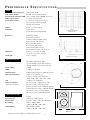
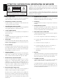
TRM6
Free Field Frequency Response 55Hz-21kHz, ±2dB
Peak Acoustic Output ≥119dB (per pair w/music @ 1m)
Total Harmonic Distortion (THD) <0.5%, 150Hz-21kHz (90dB @ 1m on axis)
High Frequency Driver 1" (25mm) Vifa Soft Dome
Low Frequency Driver 6.5" (165mm) Polypropylene Cone/
Inverted Nitrile Rubber Surround
Magnetically Shielded
Cabinet 0.26 ft
3
(7.3 liters) Vented
Front Panel: Power Switch
System LED (Power/Clip/Thermal)
Rear Panel: XLR Balanced Input
RCA Unbalanced Jack
Unbalanced/Balanced DIP Switch
Input Sensitivity DIP Switches
Bass Rolloff DIP Switches
Bass Shelving DIP Switches
Treble Shelving DIP Switches
IEC Standard Line Input / AC Line Fuse
Dimensions 8.875"W x 13.25"H x 11.50"D
(22.54cm x 33.65cm x 29.21cm)
Net Weight 23 lbs. (10.43kg)
A
MPLIFIER
S
ECTION
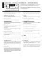
Power Rating FTC (20Hz-20kHz, 0.1% THD)
35 Watts RMS @ 6 ohms (high frequency)
50 Watts RMS @ 4 ohms (low frequency)
Signal-to-Noise >100dB
CMRR >70dB typical @ 1kHz
Input Impedance 47kΩ per phase balanced, 47kΩ unbalanced
Input Sensitivity Range 500mV to 3V (unbalanced)
275mV to 1.5V (per phase balanced)
(+4dB, +1dB, –2dB, –5dB, –8dB, –11dB)
Gain +33dB max. to +18dB min.
Power Consumption Idle Power: 11W / 150mA @ 115 VAC
(both channels driven) Idle Power: 11W / 75mA @ 230 VAC
Normal Operation: 55W / 600mA @ 120 VAC
Normal Operation: 54W / 310mA @ 230VAC
Full Power: 139W / 1.37A @ 120VAC
Full Power: 130W / 680mA @ 230VAC
C
ROSSOVER
S
ECTION
Crossover Frequency 3.2kHz
Crossover Slope 24dB/octave Linkwitz-Riley
Subsonic Filter Selectable 30Hz or 60Hz @ 12dB/octave
Bass Shelving 30Hz to 200Hz, ±4dB
(+4dB, +2dB, 0dB, –2dB, –4dB)
Treble Shelving 5kHz to 20kHz, ±4dB
(+4dB, +2dB, 0dB, –2dB, –4dB)
P ERFORMANCE SPECIFICATIONS
– i –
Specifications are subject to change without notice.
Frequency Response
@ 1m on axis
Horizontal Polar Response
Energy Time Curve
Dimensions
Side View
Front View
13.25”
8.875”
11.50”

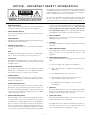
NOTICE - IMPORTANT SAFETY INFORMATION
1. READ INSTRUCTIONS
All the safety and operating instructions of your Hafler equipment
should be read before power is applied to the equipment.
2. RETAIN OWNER'S MANUAL
These safety and operating instructions should be retained for
future reference.
3. HEED WARNINGS
All warnings on the equipment and in the operating instructions are
important and should be followed.
4. FOLLOW INSTRUCTIONS
All operating and use instructions are important and should be
followed.
5. HEAT
The equipment should be kept away from areas of high tempera-
ture, i.e., heater vents, radiators, stoves/ovens, fireplaces, etc.
6. VENTILATION
The equipment should be used in an area suitable for proper
ventilation. Care should be taken not to impede airflow in and
around the cabinet.
7. WATER AND MOISTURE
The equipment should not be used in or around water, such as a
bathtub, sink, or swimming area. Also, the equipment should not
be used in areas prone to flooding, such as a basement.
8. POWER SOURCES
The equipment should be connected only to a power source of the
same voltage and frequency as that listed on the rear panel above
the power cord entry point.
9. POWER CORD PROTECTION
Power cords should be arranged so they do not interfere with the
movement of objects in the room: people, fan blades, utility carts,
etc. Also, care should be taken that the cord is not pinched or cut,
and placed so it is not in danger of being pinched or cut, as in under
a rug, around a tight corner, etc.
10. POWER CORD GROUNDING
The power supply cord is of a three wire grounded type, designed
to reduce the risk of electric shock sustained from a live cabinet. It
is assumed to be of suitable length for most uses of the equipment.
The use of extension cords and power strips is discouraged unless
they are of suitable rating to deliver the required total current for
safe operation of all connected equipment. Furthermore, extension
cords or power strips must provide the same three wire grounded
connection. It is important that the blades of the equipment’s plug
be able to fully insert into the mating receptacle. Never remove the
round grounding pin on the plug in an attempt to mate to a two
wire ungrounded receptacle: use a grounding adaptor with the
grounding tab or wire suitably connected to earth ground.
11. NON-USE PERIODS
During periods of extended non-use, the power cord should be
unplugged from the power source.
12. CLEANING
The equipment should be cleaned only as detailed in the operating
instructions.
13. OBJECT AND LIQUID ENTRY
Care should be taken so that objects and/or liquids, such as cleaning
fluids or beverages, are not spilled into the enclosure of the
equipment.
14. DAMAGE REQUIRING SERVICE
Hafler equipment should be serviced by qualified service personnel
when:
A. The power supply cord or plug has been damaged, or
B. Objects have fallen onto, or liquid has been spilled into the
equipment, or
C. The equipment has been exposed to rain, or
D. The equipment does not appear to operate normally or
exhibits a marked change in performance, or
E. The equipment has been dropped, or the enclosure has
been damaged.
15. SERVICING
The user should not attempt to service the equipment beyond that
which is described in the operating instructions. All other service
should be referred to qualified service personnel.
16. CARTS AND STANDS
The equipment should be used with carts or stands only of sufficient
strength and stability for the use intended.
An equipment and cart combination should be moved with care.
Quick stops and starts, excessive force, and uneven surfaces may
cause the equipment and cart combination to topple.
– ii –
The lightning flash with arrowhead symbol within an equilateral triangle
is intended to alert the user to the presence of uninsulated "dangerous
voltage" within the product's enclosure, that may be of sufficient magni-
tude to constitute a risk of electric shock to persons.
The exclamation point within an equilateral triangle is intended to alert
the user of the presence of important operating and maintenance
(servicing) instructions in the literature accompanying the appliance.
CAUTION
RISK OF ELECTRIC SHOCK
DO NOT OPEN
WARNING:
TO PREVENT FIRE OR SHOCK HAZARD
DO NOT EXPOSE THIS EQUIPMENT TO RAIN OR MOISTURE.
!
Page is loading ...
Page is loading ...
Page is loading ...
Page is loading ...

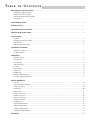
T ABLE OF CONTENTS
PERFORMANCE SPECIFICATIONS .......................................................................................................................... i
Frequency Response Graph
Energy Time Curve Graph
Horizontal Polar Response Graph
Dimensions
SAFETY PRECAUTIONS .......................................................................................................................................... ii
INTRODUCTION ................................................................................................................................................... 1
TECHNICAL DESIGN FEATURES ............................................................................................................................ 1
FRONT & REAR PANEL VIEWS............................................................................................................................... 4
INSTALLATION
Location ........................................................................................................................................................... 5
Determining Acoustic Center............................................................................................................................ 6
Input Switch ..................................................................................................................................................... 6
XLR Wiring Configurations ............................................................................................................................... 6
SCHEMATIC DIAGRAMS
Schematic Diagram .......................................................................................................................................... 7
PC Board Layout............................................................................................................................................. 11
OPERATION
Input Sensitivity .............................................................................................................................................. 12
Bass Roll Off................................................................................................................................................... 12
Bass Shelving .................................................................................................................................................. 13
Treble Shelving............................................................................................................................................... 13
AC Line .......................................................................................................................................................... 14
Power Switch ................................................................................................................................................. 14
Status LED ...................................................................................................................................................... 15
Rubber Pad..................................................................................................................................................... 15
Break-In and Warm-Up .................................................................................................................................. 15
Cleaning and Maintenance ............................................................................................................................. 15
SERVICE REFERENCE
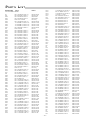
Parts List ......................................................................................................................................................... 16
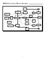
Functional Block Diagram .............................................................................................................................. 19
Circuit Operation ........................................................................................................................................... 20
Calibration ..................................................................................................................................................... 20
Input Circuit ................................................................................................................................................... 21
Tweeter Crossover .......................................................................................................................................... 21
Woofer Crossover ........................................................................................................................................... 22
Thermal Protection ......................................................................................................................................... 22
Clipping Indicator ........................................................................................................................................... 23
On Indicator ................................................................................................................................................... 23
Tweeter Replacement ..................................................................................................................................... 24
Woofer Replacement ...................................................................................................................................... 24
Amplifier Replacement ................................................................................................................................... 25
Transformer Replacement ............................................................................................................................... 25
WARRANTY ......................................................................................................................................................... 26

INTRODUCTION
– 1 –
Thank You and congratulations on your purchase of the HAFLER TRM6 reference monitor, the world's finest brand
in professional audio equipment.
The TRM6 (Trans•ana Reference Monitor) is a bi-amplified, two-way near field monitor offering unmatched
quality and performance in a truly professional grade product. The TRM6 is great for Professional Studios, Digital
Work Stations, Broadcast Booths, and Home Project Studios.
Although we realize a professional such as yourself already knows a thing or two about pro audio, we urge you to
read this manual to at least humor our technical writer. For ease of use, this manual is organized into three main
sections: Installation, Operation, and Service Reference. “Installation” covers the set-up of your new HAFLER
equipment in the system. “Operation” covers the controls and how to use them for optimum performance.
“Service Reference” contains field service information useful for technicians and engineers.
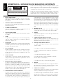
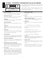
TECHNICAL DESIGN FEATURES
The TRM6 amplifiers utilize our trans•ana circuit topology employing MOSFETs in the output stage resulting in
superior sound quality.
An active 4th order Linkwitz-Riley crossover sends frequencies above 3.2kHz to a 35 watt amplifier driving
a proprietary wave guide tweeter, and frequencies below 3.2kHz to a 50 watt amplifier driving an 6"
transducer. The high frequency channel features up to ±4dB of Treble shelving, while the low frequency channel
features up to ±4dB of Bass shelving. In addition, the low frequency channel includes an active 2nd order
subsonic filter selectable to limit harmful frequencies below 30Hz or 60Hz. Monitoring
the status of both channels is done with an LED indicating Power On, Clipping and Thermal.
The high frequency transducer is a Ferrofluid cooled 1" (25mm) soft dome hemispherical tweeter utilizing a rigid
but lightweight silk diaphragm. A Phase Lens and axis-symmetric exponential waveguide improve the transition
of soundwaves from planar to spherical which result in excellent high frequency dispersion and coherent on-axis
frequency response. The low frequency transducer is a proprietary 6.5" (165mm) steel basket woofer utilizing a
20 mil polypropylene cone with a 20 mil dust cap. The suspension consists of a nitrile rubber surround and an
extended collar flat spider. The motor is constructed from a 1.25" diameter voice coil on an anodized aluminum
former with an extended vented pole piece. The 33 oz. ferrite magnet is magnetically shielded to suppress stray
leakage flux to only 4"...well within the confines of the monitor's walls, making it great for use near CRT monitors.
The cabinet is made from acoustically dead 19mm MDF, internally lined with damping material,
and features a rear firing radiused Aerovent for reduced turbulence. The outside features
a semi-gloss finish and includes a rubber pad on the underside to control vibration.

®
Amplifier
®
Clamp Bar
Heat generating component
(typically a power MOSFET or
bipolar semiconductor)
Thermal grease
Mica
Thermal grease
Heat sink
Screw
Heat path
PC Board
Heat Monster:
High output MOSFET device
Solder
Copper heat spreader
Dielectric layer
Base Layer - aluminum
Thermal grease
Heat sink
Screw, no pressure on component!
Multiple heat paths
PC Board
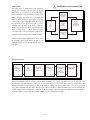
MEHSA
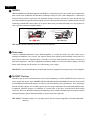
(Maximum Efficiency HeatSink Application) MEHSA is a proprietary process that yields up to 5 times better
heat transfer than traditional FET mounting techniques using the exact same components. A multi-layer
insulated metal substrate operating with minimal thermal resistance spreads heat both downward and
outward to quickly dissipate heat from each device across the heatsink. This process combined with our DSM
technology and MOSFET devices allow us to squeeze more watts per cubic inch from every output device as
well as provide consistent thermal stability.
The Way The Old Way
THE RESULT: Better reliability through faster heat dissipation.
Trans•ana
Trans•ana (TRANSconductance Active Nodal Amplifier) is a circuit that allows the audio signal to pass
through the amplifier at low voltage. The signal is directly level-shifted to the fixed high voltage rails via a
pair of driver transistors. Signal linearity is assured by an active node formed by the driver transistors at
ultrasonic frequencies. This allows amplifier performance similar to Trans•nova which is highly stable and
linear while utilizing the advantages of a non-floating power supply.
THE RESULT: An extended frequency band width accurately supplied to the output stages of the amplifier.
MOSFET Devices
HAFLER is one of the few manufacturers in the sound community to utilize MOSFET devices in both the
power supply and output stages. MOSFET (Metal Oxide Semiconductor Field Effect Transistor) devices offer
several important inherent advantages over the 30 year old technology of bi-polar design. These advantages
include: thermal stability, fast switching speed, ultra low output impedance and wide bandwidth linearity.
In addition, MOSFETs operate very similarly to vacuum tubes in that they are more linear than bipolar
transistors. However, MOSFETs can deliver the midrange clarity without the limitations of transient response
and high frequency phase shifting normally associated with tube operation.
THE RESULT: Thermal stability, fast switching speed, ultra low output impedance and wide bandwidth
linearity.
®
– 2 –

®
– 3 –
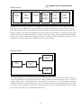
Wave Guide
The wave guide is a proprietary axis-symmetrical form of horn mounted to the tweeter to increase efficiency.
The wave guide improves the transition of sound waves (from planar to spherical) smoothly from the throat
of the wave guide to the mouth. The unique shape and smooth surfaces improve the tweeter's off-axis
frequency response as well as provide coherent on-axis response.
THE RESULT: Improves dispersion for a wider “sweet spot.”
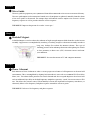
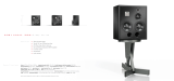
Shielded Magnet
A shielded magnet is used to reduce the radiation of high-strength magnetic fields from the woofer's motor
assembly. Suppression is accomplished by attaching a “bucking” magnet to the motor assembly in order to
keep stray leakage flux within the monitor cabinet. This type of
shielding prevents color and image distortion when placing the woofer
in close proximity to direct view (CRT) television receivers and com-
puter monitors.
THE RESULT: Prevents distortion in TV and computer monitors.
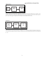
Phase Coherent
Each monitor is Phase Coherent in order to assure proper arrival times of all frequencies in the near field
environment. This is accomplished by aligning both transducer's voice coils on a common ZDP (Zero Delay
Plane) axis. The cabinet baffle positions the woofer forward and the waveguide displaces the tweeter back
with an additional 39µs delay in the high frequency amplifier to precisely “tweak” the tweeter onto its ZDP
axis. This allows the acoustic center, located midway between the high and low frequency transducers, to
coherently deliver a flat frequency and phase response around the crossover point.
THE RESULT: Delivers a flat frequency and phase response.
®
®
Tweeter
Woofer
Cabinet

ON
1234
ON
1234
ON
1234
ON
1234
A Division of Rockford Corp.
Tempe, AZ 85281 U.S.A.
Made in the U.S.A.
®
XLR Connections
3
21
+
–
5kHz 20kHz
Sensitivity
dBU input required for 100dB SPL@ 1m
SELECT ONE
0dB
0dB
30Hz
dB
+4
+2
0
–2
–4
200Hz
+4dBu
XLR
Balanced
Signal In
Trans•
ana
Reference Monitor - TRM6
250V T3A
115 V~
60 HZ
WARNING: DO NOT REMOVE COVER
TO REDUCE THE RISK OF FIRE OR ELECTRIC SHOCK
DO NOT EXPOSE THIS EQUIPMENT TO RAIN OR MOISTURE.
!
RISK OF ELECTRIC SHOCK
DO NOT OPEN
+4
+2
0
–2
–4
dB
Bass Shelving
SELECT ONE
Treble Shelving
SELECT ONE
RCA
- Unbal
- +1dBu
- -2dBu
- -5dBu
- -8dBu
- -11dBu
- 30Hz
- 60Hz
- +4dB
- +2dB
- -2dB
- -4dB
- +4dB
- +2dB
- -2dB
- -4dB
Bass Roll Off
SELECT 30Hz
OR 60Hz
30Hz 60Hz
140W
Max
CAUTION
Power
Switch
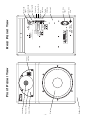
Front Panel View
– 4 –
Rear Panel View
Woofer
Tweeter
Rubber Pad
Status LED
Wave Guide
Heatsink
AC Line
Input
AC Line
Fuse
Balanced
Input
Unbalanced
Input
Sensitivity
Bass Roll Off
Bass
Shelving
Treble
Shelving
Input Switch

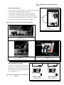
LOCATION
The location of your reference monitors in addition to the acoustics of the listening room will influence the system
frequency response. In the near field environment, our ears are more sensitive to direct sound rather than the
reverberation of sound. Below are some recommendations for the initial set-up which may help you optimize
performance in complex acoustic environments. In any configuration, keep the rear of the monitor at least 5" (12.7cm)
away from any wall or obstruction to reduce excessive boundary “loading” of the woofer vent and to optimize heat
sink cooling.
I NSTALLATION
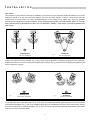
Aiming the monitors directly forward (Fig. 1) may cause response problems resulting in inadequate stereo imaging.
Aiming the monitors toward you and spaced equally like a triangle (Fig. 2) provides the best imaging and produces the
flattest frequency response.
If you frequently move your chair from side to side in front of your mixing console, positioning the tweeter and woofer
in horizontal alignment (Fig. 3) can create complex lobing patterns. Minimizing this effect can be achieved by placing
the tweeter and woofer in vertical alignment (Fig. 4). If it is essential to position the monitors horizontally, place them
with the tweeters toward the inside.
INADEQUATE
Off-Axis Response
Fig. 1
OPTIMUM
On-Axis Response
Fig. 2
INADEQUATE
Horizontal Alignment
Fig. 3
OPTIMUM
Vertical Alignment
Fig. 4
– 5 –

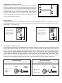
XLR Balanced Input
Check output from source for proper signal polarity
Pin 1 = GND
Pin 2 = (+)
Pin 3 = (–)
INPUT FROM
SOURCE
XLR Unbalanced Input
Connect (–) and GND (shield) terminals at
both ends
of cable to
prevent unstable amplifier operation
Pin 1 = GND
Pin 2 = (+)
Pin 3 = GND
INPUT FROM
SOURCE
1
2
3
GND
–
+
1
2
3
SHIELD
+
INPUT SWITCH
The unbalanced input uses a conventional RCA phone jack. Move the input switch ON (-->) to use this jack. The
balanced input jack is an XLR plug. The XLR jack is connected according to the IEC and AES standard. Move the input
switch OFF (<--) to use this jack.
DETERMINING ACOUSTIC CENTER
Finding the “Acoustic Center” is accomplished by positioning the
monitors so coherent arrival of the transducers occurs at ear level. The
Acoustic Center is located 3 to 4 feet in front of the monitor, measuring
perpendicularly from the center point of the cabinet (midway between
the woofer and tweeter). Our tests have shown that a flat phase and
frequency response occurs just above and below the Acoustic Center
with the minimum and maximum height spanning between the
tweeter dome and woofer dust cap.
3-4 ft.
Max. listening level
Acoustic
Center
Min. listening level
– 6 –
XLR WIRING CONFIGURATIONS
Using the balanced XLR input is recommended for installations where long cable runs are used or when the potential
for stray electromagnetic fields from other wires exists. There is a balanced and unbalanced method in which the XLR
inputs can be used. The first method is an XLR Balanced Input using 3-conductor cable. The balanced signals carried
on pins 2 and 3 are equal in amplitude and opposite in phase. Pin 1 is the ground and shield. In this configuration,
noise common on both phases of signal are effectively "canceled" out. The second method is an XLR Unbalanced Input
using 2-conductor cable with the signal carried in the center conductor and the ground carried on the shield. Many
popular mixers use unbalanced outputs and can be used with the XLR balanced input. However, in this type of
configuration we recommend using twisted pair cable or short cable length to prevent residual ground noise.
Unbalanced Input
Move input switch
RIGHT (-->) to use
RCA connector
Balanced Input
Move input switch
LEFT (<--) to use
XLR connector
+4dBu
XLR
Balanced
RCA
Unbal
- +1dBu
- -2dBu
- -5dBu
ON
1234
+4dBu
XLR
Balanced
RCA
Unbal
- +1dBu
- -2dBu
- -5dBu
ON
1234

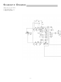
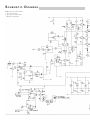
SCHEMATIC DIAGRAM
NOTES: Unless specified otherwise
1. All resistors in ohms.
2. All capacitors in microfarads.
3. Channel 1 only shown.
– 7 –

!
Qualified Service Personnel Only
–8–

Removable Center Spread
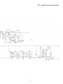
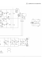
SCHEMATIC DIAGRAM
NOTES: Unless specified otherwise
1. All resistors in ohms.
2. All capacitors in microfarads.
3. Channel 1 only shown.

Removable Center Spread
!
Qualified Service Personnel Only

-11-
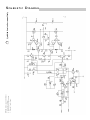
SCHEMATIC DIAGRAM
NOTES: Unless specified otherwise
1. All resistors in ohms.
2. All capacitors in microfarads.
3. Channel 1 only shown.
!
Qualified Service Personnel Only

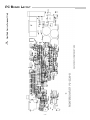
PC BOARD LAYOUT
!
Qualified Service Personnel Only
– 12 –

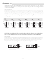
INPUT SENSITIVITY
The Input Sensitivity adjustment is used to match the monitor with signal levels from a variety of mixing consoles.
The Input Sensitivity uses DIP switches to match input levels over a 15dB range and are marked +1dB, –2dB, –5dB,
–8dB, and –11dB. These numbers indicate the input in dBu required to produce an output of 100dB SPL @ 1 meter.
When all switches are in the OFF (left) position, the monitor is matched to +4dB input level. In the +4dB switch
setting, the monitor is less sensitive to the input signal. In the –11dB switch setting, the monitor is more sensitive
to the input signal.
+4dB Input +1dB Input –2dB Input –5dB Input –8dB Input
NOTE: When using the INPUT SENSITIVITY, select only one switch configuration at a time. Engaging
multiple switch configurations (i.e., moving two or more switches ON) may cause undesirable operation and
is NOT RECOMMENDED.
I
N
P
U
T
–11dB Input
– 13 –
OPERATION
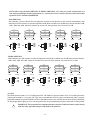
NOTE: When using the Bass Roll Off, select only the 30Hz or 60Hz filter. Engaging both switch configura-
tions at one time (both switches ON) may cause undesirable operation and is NOT RECOMMENDED.
BASS ROLL OFF
The Bass Roll Off is a subsonic filter used to limit harmful frequencies sent to the low frequency transducer to
prevent overexcursion. The filter is selectable to electronically limit frequencies below 30Hz or 60 Hz at a 12
dB/octave roll off. When both switches are in the OFF (left) position, the amplifier has an electrical -3dB
down point of 28Hz. For optimum operation select only one switch configuration at a time.
+4dBu
- +1dBu
- -2dBu
- -5dBu
- -8dBu
- -11dBu
ON
1234
ON
1234
+4dBu
- +1dBu
- -2dBu
- -5dBu
- -8dBu
- -11dBu
ON
1234
ON
1234
+4dBu
- +1dBu
- -2dBu
- -5dBu
- -8dBu
- -11dBu
ON
1234
ON
1234
+4dBu
- +1dBu
- -2dBu
- -5dBu
- -8dBu
- -11dBu
ON
1234
ON
1234
+4dBu
- +1dBu
- -2dBu
- -5dBu
- -8dBu
- -11dBu
ON
1234
ON
1234
+4dBu
- +1dBu
- -2dBu
- -5dBu
- -8dBu
- -11dBu
ON
1234
ON
1234
- 30Hz
- 60Hz
Bass Roll Off
SELECT 30Hz
OR 60Hz
30Hz 60Hz
ON
1234
- 30Hz
- 60Hz
Bass Roll Off
SELECT 30Hz
OR 60Hz
30Hz 60Hz
ON
1234
30Hz Subsonic Filter 60Hz Subsonic Filter

BASS SHELVING
Bass Shelving is used to match the low frequency response of the monitor to the acoustic environment. Bass
Shelving uses DIP switches to control frequencies from 40Hz to 200Hz over an 8dB range and are marked +4dB,
+2dB, –2dB, and –4dB. When all switches are in the OFF (left) position, the bass level is at 0dB.
NOTE: When using the BASS SHELVING & TREBLE SHELVING, select only one switch configuration at a
time. Engaging multiple switch configurations (i.e., moving two or more switches ON) may cause undesirable
operation and is NOT RECOMMENDED.
TREBLE SHELVING
Treble Shelving uses DIP switches to control frequencies from 5kHz to 20kHz over an 8dB range and are marked
+4dB, +2dB, –2dB, and –4dB. When all switches are in the OFF (left) position, the treble level is at 0dB.
40Hz
dB
+4
+2
0
–2
–4
200Hz
40Hz
dB
+4
+2
0
–2
–4
200Hz
40Hz
dB
+4
+2
0
–2
–4
200Hz
40Hz
dB
+4
+2
0
–2
–4
200Hz
40Hz
dB
+4
+2
0
–2
–4
200Hz
0dB
- +4dB
- +2dB
- -2dB
- -4dB
ON
1234
0dB
- +4dB
- +2dB
- -2dB
- -4dB
ON
1234
0dB
- +4dB
- +2dB
- -2dB
- -4dB
ON
1234
0dB
- +4dB
- +2dB
- -2dB
- -4dB
ON
1234
0dB
- +4dB
- +2dB
- -2dB
- -4dB
ON
1234
5kHz
dB
+4
+2
0
–2
–4
20kHz
5kHz
dB
+4
+2
0
–2
–4
20kHz
5kHz
dB
+4
+2
0
–2
–4
20kHz
5kHz
dB
+4
+2
0
–2
–4
20kHz
5kHz
dB
+4
+2
0
–2
–4
20kHz
0dB
- +4dB
- +2dB
- -2dB
- -4dB
ON
1234
0dB
- +4dB
- +2dB
- -2dB
- -4dB
ON
1234
0dB
- +4dB
- +2dB
- -2dB
- -4dB
ON
1234
0dB
- +4dB
- +2dB
- -2dB
- -4dB
ON
1234
0dB
- +4dB
- +2dB
- -2dB
- -4dB
ON
1234
– 14 –
–2dB
–4dB
+2dB 0dB+4dB
–2dB –4dB
+2dB
0dB
+4dB
AC LINE
The TRM6 operates from a 115 VAC/60Hz power line. The TRM6 CE operates from a 230 VAC 50/60Hz power line.
Connection is made by a 16 gauge, IEC Type 320, grounded line cord. For safety considerations only a properly
grounded (earthed) receptacle should be used. If a grounded circuit is not available, do not break off the ground pin;
use the proper adapter plug for a two wire receptacle with the grounding plug suitably connected to earth ground.
IMPORTANT: The power line fuse is mounted on the rear panel. If this fuse blows, replace it only
with the same type and rating as indicated in the parts list.
!

POWER SWITCH
The POWER switch is located on the front panel. The LED will illuminate GREEN, indicating the respective
amplifiers are on. It is possible to leave the power switch in the ON position and switch the monitor remotely
through a power distribution block or switched outlet. When doing so, make sure the switch is rated for the current
required by the monitor.
Standard practice is to turn the amplifier on last and off first when switching components to prevent
sending damaging transients to the speakers.
Es costumbre encender el amplificador de último y apagarlo de primero cuando se estan encendiendo/
apagando otros equipos, para así evitar el envío de transientes dañinas a los parlantes.
Il est de pratique courante de commencer par tourner l'amplificateur sur “off” et de terminer par “on,”
lorsqu'il s'agit de prévenir l'envoie de passages nuisible aux haut-parleurs.
Der Verstärker sollte als letztes Gerät eingeschaltet und als erstes Gerät wieder ausgeschaltet werden,
um eine Beschädigung der Lautsprecher durch spannungsspitzen zu vermeiden.
L'uso comune consiglia l'accensione dell'amplificatore per ultimo e lo spegnimento per primo quando
si accendono i vari componenti, per evitare l'invio di transitori danneggianti agli altoparlanti.
!
!
!
!
!
– 15 –
STATUS LED
Amplifier operation is monitored internally and has a status LED. This indicator can be used for system
troubleshooting in case of aberrant behavior.
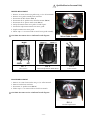
RUBBER PAD
A large rubber pad is supplied to eliminate annoying buzzes and rattles when placing the monitors on mixing
consoles or similar mounting surfaces. Attach the pad to the underside of the monitor in the following manner:
• Thoroughly clean area where pad will be positioned (i.e., with isopropyl alcohol)
• Remove paper liner from rubber pad (avoid touching adhesive with fingers)
• Position pad in desired location
• Press pad firmly to insure good contact
BREAK-IN and WARM-UP
We recommend initially breaking in the woofer for approximately 8 hours with musical information to establish
the monitor's natural bass response. To achieve the best sonic performance and image stability from the internal
amplifiers, we recommend letting them warm up for 1 hour before beginning any critical listening.
CLEANING & MAINTENANCE
There is no requirement for regular maintenance on the electronic components of the monitor. If the cabinet or
woofer becomes soiled, it can be cleaned using a damp, soft cloth. If the monitor is located in a particularly dusty
environment, cleaning the inside with compressed air or vacuuming every 18 to 24 months is sufficient.
LED – Monitors the status of the amplifiers.
*Indicates the amplifier is on regardless of input signal
COLOR STATUS
GREEN Power on*
FLASHING RED Clipping
RED Thermal
Page is loading ...
Page is loading ...
Page is loading ...
Page is loading ...
Page is loading ...
Page is loading ...
Page is loading ...
Page is loading ...
Page is loading ...
Page is loading ...
Page is loading ...
Page is loading ...
-
 1
1
-
 2
2
-
 3
3
-
 4
4
-
 5
5
-
 6
6
-
 7
7
-
 8
8
-
 9
9
-
 10
10
-
 11
11
-
 12
12
-
 13
13
-
 14
14
-
 15
15
-
 16
16
-
 17
17
-
 18
18
-
 19
19
-
 20
20
-
 21
21
-
 22
22
-
 23
23
-
 24
24
-
 25
25
-
 26
26
-
 27
27
-
 28
28
-
 29
29
-
 30
30
-
 31
31
-
 32
32
-
 33
33
-
 34
34
-
 35
35
-
 36
36


Ask a question and I''ll find the answer in the document
Finding information in a document is now easier with AI
Related papers
Other documents
-
MadBoy BOSS-10 Specification
-
Solo STK-1 Wiring guide
-
 Rockford Fosgate POWER 1000 MOSFET Owner's manual
-
 ATO SCM110ASL PRO User manual
-
Focal FPS 2160 User manual
-
Candy PGC750SQAVEU User manual
-
Hoover HF7 User manual
-
Arcam AVR250 User manual
-
 Lance-Larkin BrewExpress Brew Express CoffeeMaker User manual
-
 Aqvox PHONO 2 CI Owner's manual


