Page is loading ...

Beverage Dispensers
Mini, Standard, Heated, Whipper and Super Bowl Models
Service Manual
Table of Contents
Unpacking ................................................. 2
Installation ................................................. 2
Assembly .................................................. 3-4
Disassembly .............................................. 5
Routine Maintenance .............................. 6
Helpful Hints ............................................. 6
Preventative Maintenance ....................... 7
Security Kit Installation ............................ 8-9
Service
Base Assembly Components .............
10
Installing Pump & Fan Motors ............
10
Replacement of Compressor
Overload and Relay .............................
10
Replacement of Temperature Control .. 11
Magnetic Lock ...................................... 12
Evaporator Assembly ..........................
12
Refrigeration Test ................................ 12
Trouble Shooting Guide ........................... 13
Exploded Views ......................................... 14-19
Wiring Diagrams ........................................ 20-24
Refrigeration
Schematic ............................................ 25
Cap Tube Specs .................................. 25
Refrigerant Charges ........................... 25
Prior authorization must be obtained from
Grindmaster Corporation for all warranty claims.
Grindmaster Corporation™
4003 Collins Lane
Louisville, KY 40245 USA
(502) 425-4776 (800) 695-4500
(800) 568-5715 (Technical Service Only)
FAX (502) 425-4776
www.grindmaster.com
Grindmaster Corporation, 1996
PRINTED IN USA
Patents Pending
0404 Form #CC-375-05
Part #3275


Figure B
UNPACKING
Your dispenser is packed in 2 cartons: base pack and bowl pack.
Unpack base by opening bottom
flaps. See Figure A.
IMPORTANT NOTES:
1. Do not leave base upside down as this can damage
refrigeration system.
2. Check that all 4 rubber feet are attached to legs after removing
from base pad. Check base pad or carton for missing feet and
replace on legs.
3. Never lift from louvres/ventilation slots. Instead, place fingers
under base plate.
INST
ALLATION
1. Place base on counter.
2. For heated units (HD15/WHD15) units only:
Install Safety Arms
Tools required: Phillips Head Screwdriver
a) Place unit on its side so you have access to the bottom of the unit.
b) Line up arm holes so they line up to the holes on the bottom of the unit; arms
will extend forward as shown in illustration. See Figure B.
c) Attach arms with screws provided.
3. Leave sufficient air space (6”(15cm)) on sides (also rear of D35 triple) for proper
airflow and efficient operation. See Figure C.
IMPORTANT: Failure to provide required airspace can damage unit.
4. Plug into properly grounded, 3 prong outlet.
5. Assemble bowl parts and drain trays. See Assembly instructions that follow.
See Figure D.
NOTE: See pages 8 - 9 for Installing Security Kit Instructions.
1. Roll chassis
up-side down
2. Open bottom flaps.
Fold back.
3. Hold flaps out of way.
Roll the carton over.
4. Lift off carton.
Remove bottom pad.
BOTTOM PAD
CHASSIS
Figure A
Figure D
SPRAY TUBE
3/8” TAB
BOWL
GUIDE PIN
CHASSIS
FRONT
COOLING
PLATE
BEARING SLEEVE
IMPELLER
BOWL
GASKET
PUMP
COVER
LOCKDOWN
WASHER
SET-UP
Crathco® Beverage Dispensers Page 2
6” (15 cm)
(all units)
6” (15 cm)
(D35 only)
Figure C

Page 3 Crathco® Beverage Dispensers
PLACE BEARING SLEEVE ON
GUIDE PIN
Note flat sides on outside of
guide pin and on inside of
bearing sleeve.
Line flat sides up until bearing
sleeve slides down over guide
pin and rests on the cooling
plate.
PLACE PUMP COVER OVER GUIDE PIN
Place the pump cover over the guide pin
with the spray tube toward the front.
Note that the tab on the front of the pump
cover fits between the 2 locator buttons on
the bowl. Mini units - bent part of spray
tube faces front of bowl.
NOTE: Use agitator cover in
place of pump cover and spray tube for
fresh juice, drinks that foam (iced tea or
dairy products), or heavy viscous drinks.
PLACE IMPELLER OVER
BEARING SLEEVE.
Put impeller over bearing
sleeve with fin side up.
INSTALL LOCKDOWN WASHER OR CLAMPS
S
t
andard Units:
• Place lockdown washer over guide pin.
• Push lockdown washer down and
into locking keyway.
• Turn lockdown washer clockwise to
lock into place.
Mini Units:
• Place lockdown washer
over guide pin.
• Push lockdown washer
down and into locking
keyway.
• Slide into locked
position.
D112 Superbowl Units:
• Insert each lockdown clamp
in a lockdown pin and snap
down into place.
(Lock down 2 clamps closest to
the front of the bowl first.)
PLACE BOWL GASKET ON BOWL
Turn bowl upside down and place
bowl gasket over the neck of the
bowl. Moisten gasket with water.
NOTE: On D112 units place bowl
gasket around cooling dome.
PUT BOWL ON BASE
Place the neck of the bowl over center of the cooling
plate and with a back and forth downward motion, push bowl
down into place.
NOTE: On D112 units, place bowl over the gasket and cooling
dome with the neck of the bowl centered on the cooling dome.
ASSEMBLE VALVE
AND HANDLE
Place handle (C) in the two
V-cuts in the front of the
handle bracket (B) and
push handle back.
From inside bowl, lower the
valve (A) through the outlet
hole, and through the hole
in the handle.
Release handle.
REPLACE DRIP PAN(S)
Lower pan cover into the top of
the drip pan. Place top edge of drip
pan up under lip on front panel.
Lower each drip pan so that the
tab goes down into the tab slot
and locks pan in place.
Regular units proceed to step 15.
Whipper units proceed to step 9.
1. HOLD HANDLE IN “V”
NOTCHES & LIFT REAR
OF HANDLE UP.
2. FROM INSIDE THE
BOWL, LOWER THE
VALVE THROUGH
OUTLET HOLE, AND
THROUGH HOLE IN
THE HANDLE.
3. RELEASE HANDLE
HANDLE
O-RING
VALVE
2
3
4
1
5
6
7
LOCKDOWN
WASHER
LOCKING KEYWAY
3/8” TAB
“FRONT” OF
DISPENSER
(TOWARD VALVE AT
FRONT OF BOWL)
HEAD OF GUIDE PIN
CROSS RIBS
PUMP COVER
Assembly
8
BASEPLATE
TAB
SLOTS
FRONT PANEL LIP

Assembly (cont.)
PRESS SPRING UP INTO PLACE
AGAINST THE BOTTOM
OF THE BOWL.
ASSEMBLE THE RUBBER INLET ADAPTER
Assemble white rubber
inlet adapter by stretching one
end over the large tubular inlet
on top of the whipper housing.
Attach the other end over the
ring sleeve on the underside of
the handle.
INSERT HANDLE INTO “V” NOTCHES AND PLACE
VALVE INTO HOLE.
TURN VALVE 90° TO LOCK.
Cross slot (located on top of
valve) should run left to right
across the bowl when
locked.
PUSH WHIPPER BLADE INTO PLACE.
Replace the whipper blade by
lining up the flat inside the blade
with the flat side of the motor shaft. Push
blade firmly into place.
REPLACE WHIPPER CHAMBER.
Replace whipper chamber by
positioning the medium-sized
opening up and tilting 1/8 turn
to the right. Put whipper
chamber over whipper blade
and turn to the left until it locks
into place.
9
HANDLE SHOULDERS GO
INTO “V’ NOTCHES
RINGSLEEVE
DOWN
VALVE HOLE
SPRING
VALVE HOLE
SPRING
10
“W” IS
WHIPPER
VALVE
TOP
14
(LOOKING DOWN INTO BOWLS)
CROSS-SLOT
VALVE DOWN IN HOLE
READY TO LOCK
AFTER 90° TURN,
VALVE IS LOCKED
I/ON
SPRAY
O/OFF
I/ON
REFRIG.
O/OFF
Ring sleeve on
bottom of handle
Rubber inlet
adapter
Plastic whipper
housing
11
12
13
FILL BOWLS WITH PRODUCT
and replace lids on bowls.
Turn spray switch on first then refrigeration.
15
SPRING
VALVE
HOLE
Crathco® Beverage Dispensers Page 4

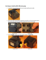
REMOVE PUMP COVER
Remove pump cover by
lifting up on spray tube.
STANDARD & MINI UNITS:
REMOVE VALVE AND HANDLE
Lift valve. Handle drops into
operator’s other hand.
WHIPPER UNITS:
• DISASSEMBLE THE RUBBER INLET
ADAPTER
Remove one end from the large tubular inlet
on top of the whipper housing and the
other end from the ring sleeve on the
underside of the handle.
• REMOVE WHIPPER CHAMBER
Turn whipper chamber to the right until it
releases and you can pull it off of the
whipper blade.
• REMOVE WHIPPER BLADE
Pull whipper blade off of the motor shaft.
• TURN VALVE 90° TO UNLOCK.
REMOVE HANDLE AND VALVE.
• REMOVE SPRING FROM
BOTTOM OF BOWL.
REMOVE BOWL AND
BOWL GASKET
Twist bowl back and forth while
lifting up. Bowl gasket will be
around bottom of bowl.
NOTE: On D112 units, bowl gasket
will be around cooling dome.
REMOVE IMPELLER AND
BEARING SLEEVE
Remove impeller and
bearing sleeve by lifting
them straight up.
NOTE: Check impeller and
bearing sleeves for wear.
See page 7.
THOROUGHLY CLEAN ALL PARTS IN WARM WATER
USING A MILD NON-ABRASIVE
DETERGENT AND
RINSE THOROUGHLY.
CAUTION
: ABRASIVES WILL SCRATCH PLASTIC PARTS.
WASH BOWL LIDS IN COOL OR LUKEWARM WATER TO
AVOID LEAKS DUE TO SEALED SURFACE BEING
DAMAGED.
REMOVE LOCKDOWN WASHER(S)
SANITIZE
Immerse parts in sanitizing solution for 1-2 minutes.
Remove parts from sanitizing solution and drain.
DO NOT RINSE. Place parts on a clean surface to air dry.
Wipe the machine, condensate tray and cooling plate
depression with a cloth wetted with sanitizer solution.
IMPORTANT: Never pour dry powder, crystals, or concentrate
into a dry bowl. Premixing beverage in separate container is
recommended. If mixing in bowl, always add water first.
2a.
3
5
6
S
tandard Unit: Twist lockdown
washer counterclockwise, slide
to release keyway. Then lift out.
Mini Unit:
Slide to release
keyway, then lift out.
D1
12 Unit: Release each clamp.
A
DISASSEMBLY
DRAIN ALL BEVERAGE FROM BOWLS
A. Remove bowl lid(s) and drip tray(s)
B. Drain through valve then
C. Tip unit forward, gently press spray
tube back a short distance to lift the
edge of the pump cover to allow
remaining beverage in well to be
drained through valve.
1
7
B
4
2b.
Ring sleeve on
bottom of handle
Rubber inlet
adapter
Plastic whipper
housing
VALVE HOLE
SPRING
VALVE
HANDLE
Page 5 Crathco® Beverage Dispensers

ROUTINE MAINTENANCE: For all Models
Cleaning Your Dispenser
To optimize performance or when using dairy products, clean unit daily.
Regular cleaning of bowl components will result in maximum pumping efficiency, proper seating and sealing, and
prevention of leaks at the valve O-Ring and bowl gasket by removing dried-on beverage solids and pulp from mov-
ing sealed parts.
1. Wash all bowl components regularly. Follow all local health codes.
* Refer to Disassembly, Cleaning, and Assembly instructions on pages 3-4.
Sanitizing Your Dispenser
* Refer to Disassembly and Assembly instructions on pages 3-4.
1. In the bowl, mix one gallon of Oxford Chemical’s Disinfectant/Sanitizer Formula C or its equivalent.
2. Turn on spray motor(s) and allow sanitizer to spray around inside of bowl for a period of time as recommended by
the sanitizer manufacturer. Formula C is satisfactory for this purpose when mixed in a solution of 1 liquid ounce of
cleaner to 4 gallons of water. Run spray motor(s) for 60 seconds. In areas with extreme hard water, consult the
local health authority.
3. Drain sanitizer completely and thoroughly during each step of the cleaning process (wash, rinse, and sanitize).
Refer to tips on draining in Disassembly Guide on page 3.
HELPFUL
HINTS
1. Noisy Impeller: Do not run impeller dry. The impeller will make a chattering sound in an empty bowl. Remove the
impeller and run a small amount of water in the bowl.
2. Valve and O-Ring: On the first installation, if there is an after-drip, place your hand on the valve and with a slight
downward pressure turn it slightly. This will help seat the o-ring so that it is properly aligned
with the valve seat. If an o-ring becomes cut or worn it should be replaced. If you are pumping
a product which has excessive pulp, a separate valve weight may be purchased to add extra
weight so the o-ring will press down against the pulp and guarantee a positive shut-off.
3. Valve Cap Use: The Valve Cap (Part # 2039) insures that a tight valve seal will occur with
products containing heavy pulp. The Valve Cap can be installed by placing it on top of the
Valve after the Valve has been assembled into the bowl. See Figure E.
4. High Water Marks on Bowl: When you agitate, you may get “high water marks” as the
beverage level drops. Keep the bowl as full as possible. Frosted bowls are available which
are helpful in reducing the appearance of water marks.
5. To Spray or Not to Spray: Most beverages can be sprayed. It is best not to spray iced tea,
iced coffee, natural juices, or beverages that foam (whipped drinks). A special agitator plate is
used in place of a pump cover and spray tube to promote circulation.
6. Proper Cooling: Always keep spray switch on when refrigeration switch is on. A unit must
spray or agitate to cool. Failure to do this will cause impeller to lock-up. The dispenser is
designed to run 24 hours a day. Keep both spray and agitate on when beverage is in the bowls.
7. Condensation: Condensation on the bowls and lids is natural, cool, and refreshing. The amount of condensation
is affected by humidity. Condensation will run down the front panel into the drip tray. Remember to occasionally
empty the drip trays.
8. Single Bowl Operation: If you find it necessary to run your dispenser with only one bowl containing beverage,
put one half (1/2) cup of water in the unused cooling plate depression(s) for best one-bowl operation and
efficiency.
VALVE CAP
VALVE
Figure E
Crathco® Beverage Dispensers Page 6

1) Wash all bowl components regularly.
2) Wash impeller and bearing sleeve individually and check for
wear.
a) Check for wear on bearing sleeve (flange should be
1.77mm thick - thickness of penny or quarter). (Figure B)
b) Check for wear on impeller (inner white center section
should be flush with colored part of impeller). (Figure A)
c) If bearing sleeve or impeller do not spin freely or are worn
- replace them. (Figure E)
d) Worn parts can cause personal injury, impair cooling and
can damage machine. (Figure C & D)
3) Check valve o-rings and bowl gaskets for wear or damage -
replace every 6 months or as needed.
4) Every 6 months or more often if needed: unplug unit, remove
panels, clean condenser and interior. (Remove dust and lint
from fins with a soft brush and vacuum.)
5) For further information, visit www.grindmaster.com or
call (800) 695-4500.
Part #s for Preventative Maintenance
Description Part #
Bearing Sleeve (all units except D112) 3220
Large Blue Impeller
(D & WD model)
1161
Small Red Impeller
(E model)
1008
Universal Impeller (all models) 3587
Valve O-ring 1012
Bowl Gasket - for D, WD models
5 gallon (or 3 gallon) bowl
1013
Bowl Gasket for E model and/or 9 liter bowl 2010
Bowl Gasket for 12 gallon SuperBowls (D112) 1150
Bearing Sleeve for 12 gallon Super Bowl (D112) 1983
New bearing sleeve
flange (approx. 1.77mm - thickness of
penny or quarter)
Worn bearing sleeve (replace
when worn to approx. 1mm or 1/2
thickness of penny or quarter).
Bearing sleeve and impeller
should spin freely when
held like this. If parts do not
spin freely or are worn, unit
will not cool properly and
worn parts may damage
machine.
worn flange
Bearing sleeve with flange missing
is extremely worn. Discard
immediately.
CAUTION: Handle with care. Sharp
edges may cause personal injury or
damage to machine.
Figure A
Figure B
Figure C
Figure D
Figure E
PREVENTATIVE MAINTENANCE
Universal Impeller
(Part # 3587)
Page 7 Crathco® Beverage Dispensers
Bottom of
Worn Impeller
Replace when worn.
Yellow or white area no
longer flush but indented.
Top of Impeller
Bottom of Unused Impeller
Yellow or white area should be
flush with colored area.

Standard Security Kit Includes
D15 D25 D35
ITEM PART # / QTY PART # / QTY PART # / QTY
KIT (contents listed below) 2509 2510 2511
PAD LOCK 1503 / (2) 1503 / (3) 1503 / (4)
COVER LOCK STRAP 2450 / (2) 2451 / (2) 2450 / (2)
VALVE LOCKING BOX 2502 / (1) 2502 / (2) 2502 / (3)
KEY VALVE LOCKING BOX 2503 / (1) 2503 / (2) 2503 / (3)
CHANNEL TOP N/A N/A 2554 / (1)
How to Assemble Bowl Locking Strap
No tools are needed to assemble kit. One pair of Cover Lock
Straps are needed per dispenser. They are designed to work
on 5 gallon bowls only with the double wall bowl cover
#2240. Each pair of cover straps uses one Padlock. The
Model D35 triple bowl unit also requires a top channel bar.
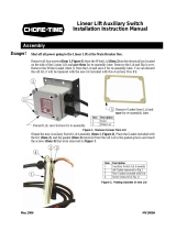
UNPLUG MACHINE BEFORE INSTALLING KIT
1) For - 3 Models (with stainless side panels), hook the
bottom end of the strap into the louvre in the top row
nearest the dispenser’s front on both sides of the
dispenser. (See Figure 1)
For - 4 Models (with plastic side panels), hook the bottom end of the strap
under the second section* of the top louvre on both sides of the dispenser.
(*note the sections under the louvres)(See Figure 1)
2) Bring both tops of the cover straps together (above the bowl cover).
3) Place padlock into the holes of the cover straps and lock together.
Note: D35 only - The top channel is interlocked into place on top of the bowls in
the same manner as described above. Interlock the side without the padlock first.
(See Figure 2)
SECOND SECTION*
FROM THE FRONT -
TOP ROW
FRONT ROW - TOP
STANDARD
- 4’S
FRONT
STANDARD
- 3’S
FRONT
Figure 1
The extended side of the box with the turned-up edge is the top.
1) Place the turned up edge (#1) over the top edge of the handle.
2) Place #2 behind the “Push” part of the handle.
3) Next, raise the box while keeping it pressed against the front panel of the dispenser. Hook the turned-up edge
(#1) over the top of the handle.
4) Slide the locking bar (#3), through the slots (#4).
5) Add the padlock through the hole and lock.
NOTE: Kit designed for “cup activated” handle (pictured). Kit will not work with “non-contact” handle.
Valve Box Locking Installation Instructions for Standard Units
SECURITY KIT INSTALLATION - STANDARD UNITS
The valve security kit locks dispense valve to prevent use when store is closed. The bowl security kit locks the lid on
the bowl to prevent unauthorized access.
Figure 2
PADLOCK HERE
Crathco® Beverage Dispensers Page 8

Mini Security Kit Includes
E27 E29 E47 E49
ITEM PART # / QTY PART # / QTY PART # / QTY PART # / QTY
KIT (contents listed below) 5350 5351 5352 5353
SECURITY BRACKET 2755 / (1) 2755 / (1) 2755 / (1) 2755 / (1)
SECURITY UPRIGHT 2756 / (1) 2943 / (1) 2756 / (1) 2943 / (1)
LOCKDOWN CHANNEL 2760 / (1) 2760 / (1) 2761 / (1) 2761 / (1)
SCREW, 10-24 X 3/4 0077 / (1) 0077 / (1) 0077 / (1) 0077 / (1)
PADLOCK 1503 / (2) 1503 / (2) 1503 / (3) 1503 / (3)
VALVE LOCKING BOX 3203 / (2) 3203 / (2) 3203 / (4) 3203 / (4)
LOCKING BAR 3202 / (1) 3202 / (1) 3202 / (2) 3202 / (2)
CAP NUT 0053 / (2) 0053 / (2) 0053 / (2) 0053 / (2)
5/16 SS SCREW 0061 / (2) 0061 / (2) 0061 / (2) 0061 / (2)
SECURITY CLAMP 2754 / (1) 2754 / (1) 2754 / (1) 2754 / (1)
Tools required: 1 regular blade screwdriver,
1 Phillips screwdriver
Instructions:
UNPLUG MACHINE BEFORE INSTALLATION
1) Remove all bowls from unit.
2) Remove the left side panel and back panel.
3) Clip security bracket over the back lip of top tray
between the bowl indentations. (see drawing)
4) Reassemble back and side panel. The back panel
fits over the security bracket.
5) Situate the security clamp over the drip lip and
tighten the screw (#0077), so the tab, located on
the back of the security clamp, slides into the security
bracket’s slot. (see drawing)
6) Bolt the security upright onto the security clamp using
2 cap nuts and 5/16 SS screws provided. (see drawing)
7) Reassemble the bowls on the unit.
8) Place the lockdown channel on top of bowls, making sure
the lockdown channel’s opening slips into the security
upright’s notch.
SECURITY KIT INSTALLATION - MINI MODELS
Padlock
5/16 Screw
Security Clamp
Front of Unit
Cap Nut
Back of Unit
Top Tray
Lockdown Channel
Security Upright
Security Bracket
Screw
10-24 x 3/4
Drip Lip
The valve security kit locks dispense valve to prevent use when store is closed. The bowl security kit locks the lid on
the bowl to prevent unauthorized access.
Valve Locking Device Installation Steps
1) Place locking box underneath bowl where valve protrudes.
2) Insert locking bar through the slits on each side of the locking
box.
• For Models E27 and E29 put the locking bar through both boxes.
• For Models E47 and E49 put the locking bar through two of
the locking boxes from the center with the lock on the outside.
Next, install the two other boxes from the outside to the center.
3) Place the padlocks into the hole on each locking bar and lock.
NOTE: Kit designed for “cup activated” handle (pictured). Kit will
not work with “non-contact” handle.
Valve
Handle
Step 1
Step 2
Step 3
Mini Model Valve
Locking Device
Exploded View
Page 9 Crathco® Beverage Dispensers

BASE ASSEMBLY COMPONENTS (Refrigerated Unit)
Compressor
Pump Motor
(one for each bowl)
Evaporator
Assembly
Thermostat
and Power
Switches
Condenser
Condenser fan
and motor
Refrigeration
Tubing
(Model D35 shown here)
INSTALLING PUMP AND FAN MOTORS: For All Models
Tools Required: Phillips screwdriver
1. Disconnect from power.
2. Remove cabinet panels.
3. Disconnect wires leading from motor to terminal board and/or switch.
4. Loosen bolts holding motor in place and replace with new motor.
NOTE: Loosen bolts that hold top tray to frames for easier pump motor installation. Retighten bolts after reassembly.
5. Connect wires from new motor to terminal board and switch.
6. Replace cabinet panels.
NOTE: When installing or repairing the pump it is important to adjust the magnetic lock. On page 5 are the instruc-
tions that should be followed for adjusting the magnetic lock (See Figure N).
REPLACEMENT OF COMPRESSOR OVERLOAD
AND RELAY:
(Figure Q)
For Standard, Whipper and Mini Models
1. Disconnect from power and remove front panel.
2. Remove plastic cover (A) and lock wire (E27s
have a nut to unscrew) (B) from compressor housing
and note positions of overload (C), relay (D) and wiring.
3. Disconnect overload (C) from housing and wires, put
overload spring clip (E) on new overload, then rewire
and replace in proper position on compressor.
4. Pull off relay (D) and disconnect wires, then rewire and
push new relay onto the compressor terminals (F).
5. Replace plastic cover (A) and lock wire (B), front panel
of dispenser and service cord to power supply.
Figure Q
E
C
F
A
B
D
F
SERVICE
Crathco® Beverage Dispensers Page 10

REPLACEMENT OF TEMPERATURE CONTROL (PART # 1059)
Tools Required: Phillips Screwdriver; Grease or Petroleum Jelly; Putty or similar substance
1. Unplug unit.
2. Remove front panel and side panel, located on the switch side, to access the temperature control mounting
screws, located on the front right corner of the frame.
3. Remove the two (2) terminals to the control. Remove the two (2) screws holding the control to the frame.
4. Pull the control tube out of the evaporator, noting its direction and length it was inserted into the evaporator.
5. Straighten the new tube out and lubricate it with grease or petroleum jelly if possible.
6. Slide the control into the copper tube inside the evaporator.
7. Make sure the control slides into the tube the same distance as the old one. Reseal the opening with putty or a
similar substance.
8. Bend excess tubing away from the fan blade.
9. Reassemble the terminals, screws and panels.
10. The control is in approximate calibration and the bowl temperature should be between 35 and 40 degrees. Minor
adjustments can be made by turning the cut in/cut out adjustments screws on the control side.
Remote bulb
inserted into
evaporator
Temperature
Controller
Remote bulb
inserted
into
evaporator
TEMPERATURE CONTROLLER
EVAPORATOR TRAY
Condensate
Tray
Evaporator
Tubing
Thermostat
Well
Page 11 Crathco® Beverage Dispensers

MAGNETIC LOCK
Magnetic Lock Problems
If a unit is not spraying, check the following:
a) The impeller must spin freely when the bearing sleeve is held between
the thumb and the forefinger,
b) The impeller should turn when assembled and the motor switch is
turned “ON”.
c) The pump motor runs without the impeller in place.
d) The air-gap between the drive magnet and the impeller is too great,
causing a loss of “magnetic lock”.
NOTE: When adjusting the drive magnet on the pump motor shaft, place
the drive magnet assembly as high as possible and still leave 1/16” clear-
ance between the magnet and the underside of the top tray. The spacers on the motor bracket may be removed first
for easier access.
Magnetic Lock Adjustment
1. Remove the pump motor assembly from the unit by loosening the (2) pump motor bolts with a 7/16 wrench. (To
remove the left pump motor assembly on a D25, you will have to remove the (2) bolts that connect the frame to
the top tray on the left side and raise the frame slightly to slide the motor out.)
2. With a 3/32 Allen Wrench, loosen the (2) set-screws on the drive magnet and raise the magnet. The magnet
should be as close as possible to the evaporator cover without rubbing. Tighten the set-screws and replace the
pump motor assembly.
Figure N
THIS IS A TRIAL AND ERROR ADJUSTMENT
BEARING SLEEVE
IMPELLER
STAINLESS TOP
TRAY
3/32” ALLEN SET
SCREW
GUIDE PIN
PUMP
MOTOR
NUT
T
OP TRAY ASSEMBLY STEPS (EVAPORATOR ASSEMBLY)
1. Unplug the unit.
2. Remove all panels.
3. Remove 4 tray mounting bolts in upper corners.
4. Evacuate refrigerant.
5. Disconnect pump motor wires.
6. Unsolder suction line and capillary tube.
7. Replace filter drier.
8. Swap pump motor assemblies to new evaporator assembly.
9. Reassemble.
10. Evacuate and charge system.
REFRIGERATION TEST
1. Add water to well.
2. Turn unit ON - if
refrigeration is OK
a frost pattern will
form in less than 5
minutes.
Crathco® Beverage Dispensers Page 12

PROBLEM POSSIBLE CAUSE SOLUTION
No or partial Refrigeration:
Compressor Runs
Note: Unit must spray or agitate
properly to obtain cooling
• Not clear air flow
• Condenser clogged with dust or lint
• Faulty fan motor
• Loss of refrigerant
• Fan blade hitting wires or tubing
• Provide 6” clearance on sides and back
• Remove front panel and clean out all lint and
dust . Use vacuum cleaner or bottle brush.
• Replace motor
• Return to factory - call for RMA.
• Bend wires or tubing to clear.
No Refrigeration:
Compressor Does Not Run
Note: Unit must spray or agitate
properly to obtain cooling
• Defective compressor overload protector
• Compressor cycles on overload protector
• Faulty refrigeration switch
• Temperature control open
• Faulty electrical connection
• After checking all of above, if compressor
doesn’t run
• Replace.
• Check for low line voltage. Then check relay
and overload and replace if necessary.
• Replace switch.
• Replace temperature control.
• Locate and correct.
• Return to factory - call for RMA.
No Spray or Agitation:
Spray Motor Runs
• Pump impeller does not spin; check for worn
bearing sleeve and/or impeller (impeller
rubbing on stainless steel evaporator)
• Pump impeller does not spin freely on
bearing sleeve.
• Impeller chatters but does not spin properly
• Replace sleeve and/or impeller.
• Clean impeller bearing. Ream out impeller
bearing if necessary. Impeller must spin
freely on bearing sleeve.
• Raise drive magnet higher on motor shaft,
but not high enough to rub.
No Spray: Spray Motor
Doesn’t Run
• Loose electrical connection to motor
• Faulty spray switch
• Faulty motor
• Drive magnet binds on plastic
evaporator cover
• Locate and correct
• Replace spray switch
• Replace motor
• Relocate magnet (NOTE: Magnet
should be about 1/16” from plastic to
prevent binding or rubbing.)
Leaky Bowl • Gasket improperly installed
• Worn or nicked bowl gasket
• Ordinary condensation build-up
• Reinstall gasket. Check directions for
bowl assembly.
• Replace gasket
• Keep drip pan attached to catch
condensation.
Noisy Unit • Worn bearings in either fan or pump motor
• Bent fan blade
• Pump impeller and/or sleeve chattering
• Replace motor(s)
• Re-bend fan blade to correct alignment
• Replace impeller and/or sleeve
Unit Does Not Heat • Loose electrical connection to heating
element
• Locate and correct
Unit Overheats • Faulty thermostat • Replace thermostat
Trouble Shooting Guide
If you still need help, call an authorized dealer in your area or Grindmaser Corporation’s Technical Service Department. You can reach
Technical Service at (800) 425-4776 Monday-Friday, 8:00 AM-6:00 PM Eastern Standard Time. Please have the model and serial number
ready so that accurate information can be given.
Prior authorization must be obtained from Grindmaster Corporation’s Technical Service Department for all warranty claims.
Page 13 Crathco® Beverage Dispensers

Exploded View
Standard and
Whipper Models
(D15, D25, D35, & WD)
Crathco® Beverage Dispensers Page 14

Parts List
Standard and Whipper Models
Page 15 Crathco® Beverage Dispensers

Standard Whipper Components
Crathco® Beverage Dispensers Page 16

Exploded View
Mini Models
(E27/9 or E47/9)
Page 17 Crathco® Beverage Dispensers

Parts List
Mini Models (E27/9 or E47/9)
Crathco® Beverage Dispensers Page 18

Exploded View and Parts List
HD15 - Heated Models
Page 19 Crathco® Beverage Dispensers
/