Page is loading ...

OMM141979 J9
J9
Mechanical Tiller
30-Inch
OPERATOR’S MANUAL
North American Version
Litho in U.S.A.

Introduction
INTRODUCTION
Introducti on
Thank You for Purchasing This Product
We appreciate your business and wish you many years of
safe and satisfied use of your machine.
Using Your Operator’s Manual
This manual is an important part of your machine and
should remain with the machine when you sell it.
Reading your operator’s manual will help you and others
avoid personal injury or damage to the machine.
Information given in this manual will provide the operator
with the safest and most effective use of the machine.
Knowing how to operate this machine safely and correctly
will allow you to train others who may operate this machine.
Section in your operator’s manual are placed in a specific
order to help you understand all the safety messages and
learn the controls so you can operate this machine safely.
You can also use this manual to answer any specific
operating or servicing questions. A convenient index
located at the end of this book will help you to find needed
information quickly.
The machine shown in this manual may differ slightly from
your machine, but will be similar enough to help you
understand our instructions.
RIGHT-HAND and LEFT-HAND sides are determined by
facing in the direction the machine will travel when going
forward. When you see a broken line arrow (------>), the
item referred to is hidden from view.
Special Messages
Your manual contains special messages to bring attention
to potential safety concerns, machine damage as well as
helpful operating and servicing information. Please read all
the highlighted information carefully to avoid injury and
machine damage.
NOTE: General information is given throughout the
manual that may help the operator in the operation of
the machine.
cCAUTION: Avoid injury! !
This symbol and text highlight potential
hazards or death to the operator or bystanders
may occur if the hazards or procedures are
ignored.
IMPORTANT: Avoiddamage!!Thistextisusedto
tell the operator of actions or conditions that might
result in damage to the machine.

Product Identification
PRODUCT IDENTIFICATION
Product Identification
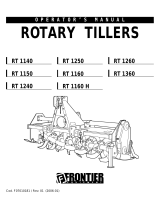
Record Identification Numbers
Mechanical Tiller
30-Inch Serial No. (010001 - )
If you need to contact an Authorized Service Center for
information on servicing, always provide the product model
and serial number.
You will need to locate the identification number for the
machine and for the engine. Record the information in the
spaces provided below.
DATE OF PURCHASE:
_________________________________________
DEALER NAME:
_________________________________________
DEALER PHONE:
_________________________________________
SERIAL NUMBER (A):
__ __ __ __ __ __ __ __ __ __ __ __ __ __ __ __ __
M96308
A

Table of Contents
TABLE OF CONTENTS
All information, illustrations and
specifications in this manual are based
on the latest information at the time of
publication. The right is reserved to
make changes at any time without
notice.
COPYRIGHT© 1999
Deere & Co.
John Deere Worldwide Commercial and
Consumer Equipment Division
Horicon, WI
All rights reserved
Previous Editions
COPYRIGHT©
OMM141979 J9 - English
Table of Contents
Safety ..........................................................................................1
PreparsVehicle ...................................................................................4
Installing . . . . . . . . . . . . . . . . . . . . . . . . . . . . . . . . . . . . . . . . . . . . . . . . . . . . . . . . . . . . . . . . . . . . . . . . . . . . . . . . . . . . . . . . .5
Removing........................................................................................9
Operating...................................................................................... 12
Service.........................................................................................17
Troubleshooting ..................................................................................23
Storage.........................................................................................24
Assembly.......................................................................................25
Specifications....................................................................................29
Index...........................................................................................30

Safety - 1
SAFETY
Safety
Understanding The Machine Safety Labels
The machine safety labels shown in this section are placed
in important areas on your machine to draw attention to
potential safety hazards.
On your machine safety labels, the words DANGER,
WARNING, and CAUTION are used with this safety-alert
symbol, (
c). DANGER identifies the most serious
hazards.
The operator’s manual also explains any potential safety
hazards whenever necessary in special safety messages
that are identified with the word, CAUTION, and the safety-
alert symbol, (
c).
WARNING (A)
AVOID INJURY FROM ROTATING KNIVES
• Keep hands, feet and clothing away.
CAUTION (B)
AVOID INJURY FROM LOSS OF BRAKING OR
STEERING
• Install ballast per Operator’sManual.
CAUTION (C)
AVOID INJURY
• READ OPERATOR’SMANUAL
• Ballast power unit per operator’smanual.
• Know location and function of controls.
• Keep all shields in place.
• Stay clear of power driven parts.
• Never carry riders.
• Keep people and pets a safe distance away from
machine.
A
M74608
M74570
M74608
M74626
B
C
M74568
M74608

Safety - 2
SAFETY
BEFORE DISMOUNTING OR SERVICING
• Shut off engine and remove key.
• Lock brake for park.
• Lowerorblockupmachine.
Operate Safely
• Check vehicle brake action before you operate. Adjust or
service brakes as necessary.
• Inspect machine before you operate. Be sure hardware
is tight. Repair or replace damaged, badly worn, or missing
parts. Be sure guards and shields are in good condition
and fastened properly. Make any necessary adjustments
before you operate.
• Clear work area of objects that might be thrown. Keep
people and pets out of the work area. Stop machine if
anyone enters the area.
• If you hit an object, stop the machine and inspect it.
Make repairs before continuing operate. Keep machine
properly maintained and in good working order. Keep all
shields and guards in place and fastened properly.
• DO NOT leave machine unattended when it is running.
• Only operate during daylight or with good artificial light.
• DO NOT let anyone, ESPECIALLY CHILDREN, ride on
machine or vehicle.
• DO NOT let children or an untrained person operate
machine.
• Raise tiller as-high-as it will go before you drive between
work areas.
• DO NOT use tiller near the edge of a ditch or bank. Tiller
can push tractor.
• Slow down on slopes.
• Stop tiller when you are NOT tilling.
• Tines turn at 250 rpm and can cause serious injury.
Keep hands, feet and clothing away from tiller when tines
are turning—always keep bystanders well away.
Wear Appropriate Clothing
• Wear close fitting clothing and safety equipment
appropriate for the job.
• Wearasuitableprotectivedevicesuchasearplugs.
Loud noise can cause impairment or loss of hearing,
• DO NOT wear radio or music headphones. Safe service
and operation requires your full attention.

Safety - 3
SAFETY
Practice Safe Maintenance
• Understand service procedure before doing work. Keep
area clean and dry.
• Never lubricate, service, or adjust machine while it is
moving. Keep safety devices in place and in working
condition. Keep hardware tight.
• Keep hands, feet, clothing, jewelry, and long hair away
from any moving parts, to prevent them from getting
caught.
• Lower attachments to the ground before servicing
machine. Disengage all power and stop the engine. Lock
park brake and remove the key. Let engine cool.
• Securly support any machine elements that must be
raised for service work.
• Never run engine unless park brake is locked.
• Keep all parts in good condition and properly installed.
Fix damage immediately. Replace worn or broken parts.
Remove any buildup of grease or debris.
• Do not modify machine. Unauthorized modifications to
the machine may impair its function and safety.

Prepare Vehicle - 4
PREPARE VEHICLE
Prepare Vehicle
Remove Mower Deck
Tractor mower deck must be removed from before installing
tiller. See your tractor operator’s manual or mower deck
manual for removal instructions.
Ballasting Requirements
All tractors require front wheel weights to be installed when
using this tiller.
Follow these recommendations to help improve traction:
• Install tire chains on turf tires or install bar tires on the
tractor.
• Install rear wheel weights.
Ballast weights can be purchased from your Authorized
Service Center. See your tractor operator’s manual for
further information.

Installing - 5
INSTALLING
Installing
Park Vehicle Safely
• Stop vehicle on a level surface, not on a slope.
• Disengage PTO.
• Engage the park brake.
• STOP the engine.
• Remove the key.
• Before you leave the operator’s seat, wait for engine and
all moving parts to STOP.
Setting Depth Control Knob
Turn depth control knob (A) to “ZERO” setting (B), raised
indicator that is blank should be aligned with fender deck
raised indicator (C).
Move Implement Lift Lever
1. Pull implement lift lever (A) rearward slightly, then
depress and hold down button (B) to unlock lift lever locking
mechanism.
2. Push lift lever (A) forward out of “RAISE” position,
releasebutton(B)asyoucontinuetopushliftleverall-the-
way forward until a loud metallic-click is heard, signalling
lever is in “LOCK-OUT” position, then release lift lever—it is
now locked into “LOWER” position.
Put Tiller Frame Rails In Transport Position
1. Pull left frame rail up until locking pin (A) can be locked
into locking bracket hole. Push down on tiller housing
M96267
A
B
C
M96268
M97160
B
A
M96259
M96275
M96274
A
D
B
C

Installing - 6
INSTALLING
handle (B) to rotate tiller housing while pulling left frame rail
upwards to gain clearance to lower frame wheels (C).
2. Unlock locking pin (D) and rotate frame wheel down into
engaged position and make sure locking pin locks into
locking hole. Lock right frame wheel down into engaged
position in similar fashion.
Install Tiller On Tractor Rear-Frame Mounting
Hardware
1. Roll tiller under rear of tractor.
2. Get a helper or use a floor jack with wheels to safely lift
and install tiller, frame hooks (A) slide over spacers (B) of
rear-frame mounting hardware.
Engage Frame Support Rod
1. Move to left side, under tractor footrest—open tiller latch
clips (A) at both sides of tiller.
2. Push and hold down lift handle (B).
3. Pivot left-side frame support rod (C) upward so loop in
rod is under mounting pin (D) of tractor frame.
4. Slowly release downward pressure on lift handle (B) to
engage rod loop.
Lock Frame Wheels into Storage Position
1. Move to left rear, behind tractor drive wheels—pull and
hold out wheel locking pin (A).
2. Swing left wheel assembly (B) up into “RAISED”
position. Make sure locking pin engages hole in locking
bracket. Repeat steps for right frame wheel.
M41781
A
M96255
B
cCAUTION: Avoid injury! Maintain a secure grasp
of lift handle until support rod is in place. Keep
hands clear of pinch areas between tiller and
tractor frame.
M96279
B
D
A
C
M96277
A
B

Installing - 7
INSTALLING
Disengage Frame Support Rod
1. Move to left side, under tractor footrest—hold lift handle
(B) down.
2. Pivot support rod (C) down into storage position.
3. Slowly release downward pressure on lift handle (B)
until cups of tiller frame latches (A) are seated up against
mounting pins (D).
Fasten Frame Clip Latches And Install Belt
1. Close clip of latch (A) around mounting pin (B) on each
side of tractor.
2. Install spring locking pin (C), from bag of parts, into
holes of each clip latch (A), outside-in, to prevent clips from
vibrating or bouncing open.
3. Move to right side, under tractor footrest—swing belt
tensioning lever (D) toward front of tractor to loosen belt
tensioning idler (E).
4. Move belt tensioning idler (E), by hand, towards right
frame to help install belt on PTO drive sheave (F). Release
idler after belt is completely seated in sheave.
5. Swing belt tensioning lever (D) toward rear of tractor to
tighten belt.
Fasten Tiller Lift Rod to Tractor Lift Link
NOTE: Lock implement lift lever into “LOWER”
position and unlock tiller housing from “TRANSPORT”
position and lower it onto ground before fastening tiller
lift rod (B)—this allows ease-of-alignment between
tractor lift link (A) and tiller lift rod pin (C).
1. Move to right side, under tractor footrest—as you rotate
cCAUTION: Avoid injury!
Maintain a secure grasp of lift handle (B) until
tiller frame clips (A) are seated against
mounting pins (D).
Keep hands clear of pinch areas between tiller
and tractor frame.
M96279
C
D
B
A
A
B
C
M96280
D
IMPORTANT: Avoid damage! Check that belt
tensioning idler spring (G) is installed in top detent
of belt tensioning lever (D). Damage to spring may
occur or tensioning of idler may not apply proper
tension on drive belt if spring is installed in the
lower detent.
M96283
D
F
E
G
M96281
C
A
B
D

Installing - 8
INSTALLING
tiller lift rod (B) upright, align tractor lift link (A) so pin (C) fits
into hole (D) of lift link (A).
2. Install M13 x 24 x 2.5 mm washer (E), from bag of parts,
on lift rod pin (C).
3. Fasten lift rod to lift link with spring locking ring (F), from
bag of parts.
Adjust Tiller Lift Height
1. Push implement lift lever (A) forward slightly, then
depress and hold down button (B) to unlock lift lever locking
mechanism.
2. Pull lift lever (A) reward out of “LOWER” position,
release button (B) and continue to pull lever all-the-way
reward until a loud metallic-click is heard, signalling lever is
in “LOCK-OUT” position, then release lift lever—it is now
locked into “RAISE” position.
3. Move to left side of tiller housing—grasphandle(C)to
raise tiller housing to remove pressure on transport locking
pin (D) and continue to hold tiller housing stationary while
you pull transport locking pin (D) out and rotate it forward
into “LOCK-OUT” position,rolledpin(E)lockedinframe
slot (F).
4. Slowly lower tiller housing down (G) against tractor lift
linkage.
5. Measure distance (C) between lowest tine and ground.
Distance should be 75 mm (3-in.). This will allow a
maximum 150 mm (6-in.) tilling depth and enough ground
clearance for turns on ends of tilling area. If distance is not
correct, see Adjusting Tilling Depth in the OPERATING
section.
M96284
E
F
C
M97160
B
A
C
F
D
M96294
E
G
M96289
C

Removing - 9
REMOVING
Removing
Park Vehicle Safely
• Stop vehicle on a level surface, not on a slope.
• Disengage PTO.
• Engage the park brake.
• STOP the engine.
• Remove the key.
• Before you leave the operator’s seat, wait for engine and
all moving parts to STOP.
Move Implement Lift Lever
1. Pull implement lift lever (A) rearward slightly, then
depress and hold down button (B) to unlock lift lever locking
mechanism.
2. Push lift lever (A) forward out of “RAISE” position,
release button (B) as you continue to push lift lever all-the-
way forward until a loud metallic-click is heard, signalling
lever is in “LOCK-OUT” position, then release lift lever—it is
now locked into “LOWER” position.
Disconnect Tiller Lift Rod From Tractor Lift
Link And Unhook Right Clip Latch
NOTE: Lock implement lift lever into “LOWER”
position and unlock tiller housing from “TRANSPORT”
position and lower it onto ground before disconnecting
tiller lift rod (B)—this allows ease-of-disconnect
between tractor lift link (A) and tiller lift rod pin (C).
1. Move to right side, under tractor foot rest—remove
spring locking ring (D) and washer (E) from tiller lift rod pin
(C).
2. Pull tiller lift rod pin (C) from lift link (A) as you lower tiller
lift rod (B) inward, onto ground.
3. Store washer (E) and spring locking ring (D) on lift rod
pin (C).
4. Remove spring lockingpin from clip latch (F) and flip clip
of latch rearward to clear tractor mounting pin (G).
M97160
B
A
M96284
E
D
C
A
B
M96281
C
A
B
G
F

Removing - 10
REMOVING
Disengage Belt And Unhook Left Clip Latch
1. Move to right side, under tractor footrest—move belt
tensioning idler lever (A) out of “ENGAGED” position into
“DISENGAGED” position (pointing toward front of tractor).
2. Pull and hold tensioning idler (B) towards right frame
while you remove belt from PTO drive sheave (C).
3. Move to left side, under tractor footrest—remove spring
locking pin from clip latch (D) and flip latch of clip reward to
clear tractor mounting pin (E). Install spring locking pins in
clips for storage when finished removing tiller from tractor.
4. Move to left side of tiller housing—grasp handle (E) to
raise tiller housing to align transport locking pin (F) with
locking plate hole (G). Continue to hold tiller housing
stationary while you rotate transport locking pin handle (H)
rearward until spring tension “LOCKS-OUT” pin into
“TRANSPORT” position.
5. Slowlylift housing handle (E) up-and-down to ensure pin
is “LOCKED-OUT” before letting go of handle.
Engage Frame Support Rod
1. Move to left side, under tractor footrest—push and hold
down lift handle (A) as you pivot left-side frame support rod
(B) upward so loop in rod is under mounting pin (C) of
tractor frame.
2. Slowly release downward pressure on lift handle (A) to
engage rod loop.
A
B
C
M96283
M96280
E
D
E
F
H
M96294
G
H
cCAUTION: Avoid injury! Maintain a secure grasp
of lift handle until support rod is in place. Keep
hands clear of pinch areas between tiller and
tractor frame.
M96279
A
C
B

Removing - 11
REMOVING
Lock Frame Wheels Into Engage Position
1. Move to left rear, behind tractor drive wheels—pull and
hold out wheel locking pin (A).
2. Swing left wheel assembly (B) down into “ENGAGE”
position. Make sure locking pin engages hole in locking
bracket. Repeat for right frame wheel.
Disengage Frame Support Rod
1. Move to left side, under tractor footrest—push and hold
lift handle (A) down.
2. Pivot support rod (B) down into storage position.
3. Slowly release downward pressure on lift handle (A).
Remove Tiller From Tractor Rear-Frame
Mounting Hardware
1. Get a helper or use a floor jack with wheels to safely
support and slide tiller housing as you slide frame hooks
(A) from of rear-frame mounting hardware (B).
2. Carefully roll tiller out-from-under rear of tractor.
cCAUTION: Avoid injury! Maintain a secure grasp
of lift handle (A). Keep hands clear of pinch
areas between tiller and tractor frame.
M96277
A
A
M96279
B
A
M41781
A
M96255
B

Operating - 12
OPERATING
Operating
Tilling Tips
Install correct front and rear tractor weights. See Install
Weights and Chains in Installing the Tiller section.
Till with engine at FAST throttle, control ground speed with
appropriate transmission speed range.
Check tines before you till. Replace missing, bent, or
broken tines.
When you till hard ground or sod, till at a shallow depth for
the first pass. Till deeper on each pass after that.
When you till a small area, make a pass through the
middle, then circle alongside the original pass, working to
the outside. After you finish, make a few passes around the
edge to cover ridges left by turning.
Till straight ahead when possible. This will leave fewer
ridges from turning.
For seed bed preparation, till the soil once in the fall.
Decaying vegetation will add valuable nutrients to the soil
by spring. If the terrain is hilly or uneven, wait until spring,
or leave some untilled strips, to help reduce soil erosion.
The climate and terrain will help you decide the best time to
till.
Before Tilling
Test soil condition by squeezing it in your hand. If soil forms
a ball, it is too wet to till. If soil does not compress easily or
falls apart, it is ready to till.
DO NOT till when soil is wet. Wet soil will stick to tines and
tine shaft. Wet soil will clump-up and dryout hard, making it
difficult to work during the growing season.
Before tilling mow tall weeds and grass to keep them from
wrapping around tines or tine shaft.
Always pick up rocks, branches, and other objects that
might damage tiller.
Always check tines before tilling. Repair or replace loose,
bent, or broken tines.
Move Implement to “LOWER” Position
1. First pull implement lift lever (A) rearward slightly, then
depress and hold down button (B) to unlock lift lever locking
mechanism.
2. Push lift lever (A) forward out of “RAISE” position
(shown), release button (B) as you continue to push lift
lever all-the-way forward until a loud metallic-click is heard,
signalling lever is in “LOCK-OUT” position, then release lift
lever—it is now locked into “LOWER” position (see next
figure).
“LOCK-OUT” Position: locks tiller in “LOWER” position—for
difficult conditions, such as, heavy soils, clay, or sod. When
lift lever is “LOCKED-OUT” this means the lift spring in the
lift linkage has no effect on tiller weight.
IMPORTANT: Avoid damage!
DONOTbackupormakesharpturnswiththetiller
in the ground.
M34147
M97160
B
A

Operating - 13
OPERATING
Move Implement to “RAISE” Position
1. First push implement lift lever (A) forward slightly, then
depress and hold down button (B) to unlock lift lever locking
mechanism.
2. Pull lift lever reward out of “LOWER” position, release
button (B) and continue to pull lever all-the-way reward until
a loud metallic-click is heard, signalling lever is in “LOCK-
OUT” position, then release lift lever—it is now locked into
“RAISE” position.
“LOCK-OUT” Position: locks tiller in “RAISE” position—for
making turns at end of rows. When lift lever is “LOCKED-
OUT” this means the lift spring in the lift linkage has no
effect on tiller weight.
Move Implement to “FLOAT” Position
1. First pull implement lift lever (A) rearward slightly, then
depress and hold down button (B) to unlock lift lever locking
mechanism.
2. Push lift lever (A) out of “RAISE” position, release button
(B) and lift lever. Lift lever is now in “FLOAT” position
(between “RAISE” and “LOWER” positions).
“FLOAT” Position allows implement to move with contour of
ground which causes the lift spring in the lift linkage to exert
maximum depth force on tiller weight. “FLOAT” position
performs best in light-to-medium soils: such as sandy,
loam, or soils previously tilled.
Using Depth Control Knob
Adjust depth control knob to set tilling depth. Tiller will
return to the same depth each time you lower it.
1. Use lift lever (B) to raise tiller as high as it will go.
2. Turn knob (A) clockwise to raise the tiller depth or
counter-clockwise to lower the depth, as viewed from
operator’sseat.
3. If you cannot adjust for the desired tilling depth, see
Adjusting Tilling Depth.
Adjusting Tilling Depth
1. Stop engine and set PARK brake.
2. “LOCK-OUT” lift lever (A) into “LOWER” position to
release spring tension in lift linkage.
M97160
B
A
M97160
B
A
A
B
M96267
M97160
A

Operating - 14
OPERATING
3. Move to right side, below tractor footrest—remove
spring locking ring (A) and flat washer (B) form lift rod pin
(C).
4. Remove lift rod (D) form tractor lift link (E).
NOTE: Maximum tilling depth is 150 mm (6-in.)—
bottom of shaft to bottom edge of lowest tine.
Picture Note: Tiller frame removed from tractor for
clarity.
5. Turn lift rod (D) clockwise into clevis (F) to increase
tilling depth and counterclockwise out of clevis (F) to
decrease tilling depth.
6. Fasten lift rod (D) to tractor lift link (E) with washer (B)
and spring locking ring (A).
7. Check tiller ground clearance:
• Use lift lever to raise tiller as high as it will go.
• Measure distance (H) between ground and the
lowest tine. The distance should be 75 mm (3-in.).
Operating Tiller
1. Move to rear of tractor—lock frame wheels (A) in the
RAISED position (shown). Make sure locking pins (B) are
locked into locking bracket hole.
IMPORTANT: Avoid damage!
DO NOT expose more than 30 mm (1-1/4 in.) of
thread (G) or lift rod and clevis threads could be
damaged or lift rod could separate from clevis.
A
M96284
E
C
B
D
D
F
M96272
G
cCAUTION: Avoid injury!
• Pick up objects from tilling area.
• Guards and shields must be in place.
• Clear the work area of people.
• DO NOT let children operate the tractor/tiller.
• DO NOT let children ride on the tractor or
tiller.
H
M96289
A
M96277
B

Operating - 15
OPERATING
2. Move to left side of tiller housing—grasp handle (C) to
raise tiller housing to remove pressure on transport locking
pin (D) and continue to hold tiller housing stationary while
you pull transport locking pin (D) out and rotate it forward
into “LOCK-OUT” position,rolledpin(E)lockedinframe
slot (F).
3. Slowly lower tiller housing down (G) against tractor lift
linkage.
4. Start engine. Put throttle lever at 1/4 position. (See your
tractor operator’s manual for throttle lever operation.)
NOTE: For those tractors with Reverse Implement
Option (RIO), the tiller will stop when the tractor is put
in reverse unless Reverse Implement Switch (RIS) is
activated before going in reverse.
5. To engage tiller, put PTO control in the ON position.
(See your tractor operator's manual for PTO operation.)
6. Push throttle lever to the FAST position.
7. UNLOCK the park brake.
8. Till ground at a safe travel speed using appropriate
transmission ground speed.
Inspecting Or Unplugging Tiller
1. STOP the tractor.
2. Put PTO control in the OFF position.
3. Lower tiller to the ground.
4. LOCK the park brake.
5. STOP the engine.
6. Remove the key.
7. Move to rear of tiller—lift shield (A) to gain access to
tines and shaft.
8. Safely inspect or unplug tines and shaft area.
Parking Tiller
1. STOP tractor and turn PTO switch OFF.
2. STOP engine, LOCK park brake, and remove key.
3. Lower tiller to ground.
Transporting Tiller
Drive the tractor with the tiller in the “TRANSPORT”
position when traveling from one tilling area to the other.
Drive the tractor at a safe travel speed. Slow down on
slopes or rough ground.
Place tiller in “TRANSPORT” position as follows:
1. First push implement lift lever (A) forward slightly, then
depress and hold down button (B) to unlock lift lever locking
cCAUTION: Avoid injury! Stop the engine and
wait for all moving parts to stop before leaving
tractor seat.
C
F
D
M96294
E
G
M96293
A
M97160
B
A

Operating - 16
OPERATING
mechanism.
2. Pull lift lever (A) reward out of “LOWER” position
(shown),releasebutton(B)andcontinuetopullleverall-
the-way reward until a loud metallic-click is heard,
signalling lever is in “LOCK-OUT” position, then release lift
lever—it is now locked into “RAISE” position, lift lever in
close proximity to steering wheel.
3. Move to left side of tiller housing—grasp handle (C) to
raise tiller housing to align transport locking pin (D) and
transport bracket locking hole (E). Rotate transport locking
pin (D) reward to unlock rolled pin (F) from frame slot (G)
and release transport locking pin so it springs into “LOCK-
OUT” position in transport bracket locking hole (E).
4. Slowly lift up and push down on handle (C) before
releasing it to ensure tiller housing is “LOCKED-OUT” into
“TRANSPORT” position.
C
G
D
M96294
F
E
/